EP2777857A2 - Verbindungsverfahren und Flüssigkeitsbehandlungssystemen zur Verbindung unter Einwirkung eines temperaturgeregelten Fluides - Google Patents
Verbindungsverfahren und Flüssigkeitsbehandlungssystemen zur Verbindung unter Einwirkung eines temperaturgeregelten Fluides Download PDFInfo
- Publication number
- EP2777857A2 EP2777857A2 EP14158804.6A EP14158804A EP2777857A2 EP 2777857 A2 EP2777857 A2 EP 2777857A2 EP 14158804 A EP14158804 A EP 14158804A EP 2777857 A2 EP2777857 A2 EP 2777857A2
- Authority
- EP
- European Patent Office
- Prior art keywords
- controlled fluid
- temperature controlled
- article
- temperature
- joining
- Prior art date
- Legal status (The legal status is an assumption and is not a legal conclusion. Google has not performed a legal analysis and makes no representation as to the accuracy of the status listed.)
- Withdrawn
Links
Images

Classifications
-
- B—PERFORMING OPERATIONS; TRANSPORTING
- B23—MACHINE TOOLS; METAL-WORKING NOT OTHERWISE PROVIDED FOR
- B23K—SOLDERING OR UNSOLDERING; WELDING; CLADDING OR PLATING BY SOLDERING OR WELDING; CUTTING BY APPLYING HEAT LOCALLY, e.g. FLAME CUTTING; WORKING BY LASER BEAM
- B23K37/00—Auxiliary devices or processes, not specially adapted for a procedure covered by only one of the other main groups of this subclass
- B23K37/003—Cooling means for welding or cutting
-
- B—PERFORMING OPERATIONS; TRANSPORTING
- B23—MACHINE TOOLS; METAL-WORKING NOT OTHERWISE PROVIDED FOR
- B23K—SOLDERING OR UNSOLDERING; WELDING; CLADDING OR PLATING BY SOLDERING OR WELDING; CUTTING BY APPLYING HEAT LOCALLY, e.g. FLAME CUTTING; WORKING BY LASER BEAM
- B23K1/00—Soldering, e.g. brazing, or unsoldering
- B23K1/0008—Soldering, e.g. brazing, or unsoldering specially adapted for particular articles or work
- B23K1/0018—Brazing of turbine parts
-
- B—PERFORMING OPERATIONS; TRANSPORTING
- B23—MACHINE TOOLS; METAL-WORKING NOT OTHERWISE PROVIDED FOR
- B23K—SOLDERING OR UNSOLDERING; WELDING; CLADDING OR PLATING BY SOLDERING OR WELDING; CUTTING BY APPLYING HEAT LOCALLY, e.g. FLAME CUTTING; WORKING BY LASER BEAM
- B23K20/00—Non-electric welding by applying impact or other pressure, with or without the application of heat, e.g. cladding or plating
- B23K20/12—Non-electric welding by applying impact or other pressure, with or without the application of heat, e.g. cladding or plating the heat being generated by friction; Friction welding
- B23K20/129—Non-electric welding by applying impact or other pressure, with or without the application of heat, e.g. cladding or plating the heat being generated by friction; Friction welding specially adapted for particular articles or work
-
- B—PERFORMING OPERATIONS; TRANSPORTING
- B23—MACHINE TOOLS; METAL-WORKING NOT OTHERWISE PROVIDED FOR
- B23K—SOLDERING OR UNSOLDERING; WELDING; CLADDING OR PLATING BY SOLDERING OR WELDING; CUTTING BY APPLYING HEAT LOCALLY, e.g. FLAME CUTTING; WORKING BY LASER BEAM
- B23K26/00—Working by laser beam, e.g. welding, cutting or boring
- B23K26/34—Laser welding for purposes other than joining
-
- B—PERFORMING OPERATIONS; TRANSPORTING
- B23—MACHINE TOOLS; METAL-WORKING NOT OTHERWISE PROVIDED FOR
- B23K—SOLDERING OR UNSOLDERING; WELDING; CLADDING OR PLATING BY SOLDERING OR WELDING; CUTTING BY APPLYING HEAT LOCALLY, e.g. FLAME CUTTING; WORKING BY LASER BEAM
- B23K31/00—Processes relevant to this subclass, specially adapted for particular articles or purposes, but not covered by any single one of main groups B23K1/00 - B23K28/00
- B23K31/02—Processes relevant to this subclass, specially adapted for particular articles or purposes, but not covered by any single one of main groups B23K1/00 - B23K28/00 relating to soldering or welding
-
- B—PERFORMING OPERATIONS; TRANSPORTING
- B23—MACHINE TOOLS; METAL-WORKING NOT OTHERWISE PROVIDED FOR
- B23K—SOLDERING OR UNSOLDERING; WELDING; CLADDING OR PLATING BY SOLDERING OR WELDING; CUTTING BY APPLYING HEAT LOCALLY, e.g. FLAME CUTTING; WORKING BY LASER BEAM
- B23K5/00—Gas flame welding
- B23K5/18—Gas flame welding for purposes other than joining parts, e.g. built-up welding
-
- B—PERFORMING OPERATIONS; TRANSPORTING
- B23—MACHINE TOOLS; METAL-WORKING NOT OTHERWISE PROVIDED FOR
- B23K—SOLDERING OR UNSOLDERING; WELDING; CLADDING OR PLATING BY SOLDERING OR WELDING; CUTTING BY APPLYING HEAT LOCALLY, e.g. FLAME CUTTING; WORKING BY LASER BEAM
- B23K9/00—Arc welding or cutting
- B23K9/04—Welding for other purposes than joining, e.g. built-up welding
- B23K9/044—Built-up welding on three-dimensional surfaces
-
- B—PERFORMING OPERATIONS; TRANSPORTING
- B23—MACHINE TOOLS; METAL-WORKING NOT OTHERWISE PROVIDED FOR
- B23K—SOLDERING OR UNSOLDERING; WELDING; CLADDING OR PLATING BY SOLDERING OR WELDING; CUTTING BY APPLYING HEAT LOCALLY, e.g. FLAME CUTTING; WORKING BY LASER BEAM
- B23K2101/00—Articles made by soldering, welding or cutting
- B23K2101/001—Turbines
-
- B—PERFORMING OPERATIONS; TRANSPORTING
- B23—MACHINE TOOLS; METAL-WORKING NOT OTHERWISE PROVIDED FOR
- B23P—METAL-WORKING NOT OTHERWISE PROVIDED FOR; COMBINED OPERATIONS; UNIVERSAL MACHINE TOOLS
- B23P6/00—Restoring or reconditioning objects
- B23P6/002—Repairing turbine components, e.g. moving or stationary blades, rotors
- B23P6/007—Repairing turbine components, e.g. moving or stationary blades, rotors using only additive methods, e.g. build-up welding
-
- F—MECHANICAL ENGINEERING; LIGHTING; HEATING; WEAPONS; BLASTING
- F01—MACHINES OR ENGINES IN GENERAL; ENGINE PLANTS IN GENERAL; STEAM ENGINES
- F01D—NON-POSITIVE DISPLACEMENT MACHINES OR ENGINES, e.g. STEAM TURBINES
- F01D5/00—Blades; Blade-carrying members; Heating, heat-insulating, cooling or antivibration means on the blades or the members
- F01D5/005—Repairing methods or devices
-
- F—MECHANICAL ENGINEERING; LIGHTING; HEATING; WEAPONS; BLASTING
- F01—MACHINES OR ENGINES IN GENERAL; ENGINE PLANTS IN GENERAL; STEAM ENGINES
- F01D—NON-POSITIVE DISPLACEMENT MACHINES OR ENGINES, e.g. STEAM TURBINES
- F01D9/00—Stators
- F01D9/02—Nozzles; Nozzle boxes; Stator blades; Guide conduits, e.g. individual nozzles
- F01D9/04—Nozzles; Nozzle boxes; Stator blades; Guide conduits, e.g. individual nozzles forming ring or sector
Definitions
- the subject matter disclosed herein relates to joining methods and temperature controlled fluid treating systems and, more specifically, to joining methods and temperature controlled fluid treating systems for controlling temperature profiles of articles.
- gas turbine engines such as aircraft engines for example
- air is drawn into the front of the engine, compressed by a shaft-mounted rotary-type compressor, and mixed with fuel.
- the mixture is burned, and the hot exhaust gases are passed through a turbine mounted on a shaft.
- the flow of gas turns the turbine, which turns the shaft and drives the compressor and fan.
- the hot exhaust gases flow from the back of the engine, driving it and the aircraft forward.
- the temperatures of combustion gases may exceed 3,000°F, considerably higher than the melting temperatures of the metal parts of the engine which are in contact with these gases.
- Operation of these engines at gas temperatures that are above the metal part melting temperatures is a well-established art, and depends in part on supplying a cooling air to the outer surfaces of the metal parts through various methods.
- the metal parts of these engines that are particularly subject to high temperatures, and thus require particular attention with respect to cooling are the metal parts forming combustors and parts located aft of the combustor, in the so-called "hot gas path".
- the operating temperatures can be partially regulated by using passageways such as cooling holes incorporated into some engine components.
- Superalloys such as precipitation-hardenable Ni-based superalloys, or Co-based superalloys
- the repair of these materials and components may also require significant resources such as to properly preheat and/or cool weld repair sites.
- the large size of these components can also prevent some preheating devices (e.g., induction heaters) from effectively preheating the necessary area.
- the preheating, cooling and any other temperature cycling can thus require additional resources and time to allow for sufficient joining of additional material for modifications or repairs.
- a method of joining material to an article comprising one or more passageways.
- the method includes fluidly connecting a temperature controlled fluid source comprising temperature controlled fluid to at least one passageway and passing the temperature controlled fluid through the at least one passageway, wherein the temperature controlled fluid at least partially controls a temperature profile of the article.
- the method further includes joining material to the article, wherein the temperature profile of the article at least partially controls a resulting joined material characteristic.
- a temperature controlled fluid treating system for joining material to an article comprising one or more passageways.
- the temperature controlled fluid treating system includes a temperature controlled fluid source that fluidly connects to at least one passageway of the article and passes a temperature controlled fluid through the passageway, wherein the temperature controlled fluid at least partially controls a temperature profile of the article.
- the temperature controlled fluid treating system further includes a material joining apparatus that joins material to the article, wherein the temperature profile of the article at least partially controls a joined material characteristic.
- Temperature controlled fluid treating systems disclosed herein generally comprise a temperature controlled fluid source and a material joining apparatus to join material to the target location of an article comprising passageways.
- temperature controlled fluid is fluidly connected to the passageways and passed there through to at least partially control the temperature profile of the article, which in turn at least partially controls a characteristic (e.g., microstructure) of the joined material.
- joind material may refer to the article itself or to material added to the article, such as, for example, welding material. Temperature controlled fluid treating systems and methods of joining material to an article will be discussed in more detail herein.
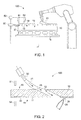
- a temperature controlled fluid treating system 100 comprising a material joining apparatus 20 and a temperature controlled fluid source 30 for joining material to an article 10.
- the article 10 can comprise a variety of different types of articles such as components for a turbine.
- the article 10 can comprise a transition piece, liner, bucket, blade, vane, nozzle, or shroud.
- the article 10 can comprise a turbine component such as a hot gas path component or a combustion component.
- the article 10 can comprise any other component of a turbine such as a component for a gas turbine, industrial gas turbine, steam turbine or the like.
- the article 10 can have a temperature profile that comprises the specific temperature at each respective location on and about the article 10.
- the temperature profile can vary with respect to location and can depend on a variety of factors such as external temperatures, the temperature of the joined material and the like. Specifically, the temperature profile can also depend at least in part on the temperature of the temperature controlled fluid that passes through the passageways 12.
- the article 10 comprises one or more passageways 12 passing at least partially through the article 10.
- the one or more passageways 12 pass from a first end 18 to a second end 19.
- the one or more passageways 12 may pass from a first end 18, serpentine through a portion of the article 10 and then exit back through the first end 18 without breaching the second end 19.
- the passageways 12 can thus comprise any passage that at least partially passes through the article 10 and can allow for temperature controlled fluid 35 that passes there through to at least partially control the temperature profile of the article 10 as will become appreciated herein.
- at least one of the one or more passageways 12 can comprise a cooling hole.
- cooling hole refers to a passageway 12 that passes from a first end 18 to a second end 19 of the article 10 and that is used to help cool the article 10 during operation.
- the second end 19 of the article 10 comprises a target location 11 that is to have joined material 22 joined thereto.
- the target location 11 may have joined material 22 joined prior to first use, during routine or unscheduled repair maintenance, or as otherwise necessary depending on the life of the article 10.
- joining material can repair damaged sites, connect multiple articles together or otherwise build up additional material not already present.
- joining material may add material that is the same as or similar to the substrate to allow for more closely matched properties between the joined material 22 and the article 10.
- the material may be dissimilar. Dissimilar materials may be used, for example, to provide enhanced characteristics that address the defect mode and surface requirements of a particular area of an article. For example, the dissimilar material may provide better oxidation resistance, creep, low cycle fatigue, wear properties, or a combination of these.
- the article 10 may be disposed on a support stand 15 prior to or during the joining of material as will become appreciated herein.
- the support stand 15 may be stationary or mobile (e.g., rotatable) and position the article 10 relative to the material joining apparatus 20 and the temperature controlled fluid source 30 when joining material to the target location 11 of the article 10.
- the temperature controlled fluid treating system 100 further comprises the material joining apparatus 20.
- the material joining apparatus 20 comprises any device that joins material to a target location 11 of the article 10 with a joined material 22.
- the material joining apparatus 20 can comprise a welder such as an induction welder, an arc welder (e.g., a TIG welder), a gas welder (e.g., an oxyacetylene torch), an energy beam welder (e.g., a laser beam welder) and/or any other type of welder that can melt and deposit weld material 25 (as illustrated) onto the target location 11 of the article 10.
- the material joining apparatus may enable other joining methods such as brazing, solid state joining methods (e.g., diffusion bonding, friction welding, resistance welding) or the like.
- the material joining apparatus 20 may be disposed at any position relative to the article 10 that allows for joining material to the target location 11.
- the article 10 may be disposed on a support stand 15 adjacent the material joining apparatus 20.
- the support stand 15 may then be able to rotate or otherwise displace the article 10 with respect to the material joining apparatus 20 and/or the material joining apparatus 20 may be able to articulate with respect to the article 10.
- the material joining apparatus 20 may then be used to apply joined material (e.g. the weld material 25 as illustrated) onto the target location 11 of the article 10.
- the temperature controlled fluid treating system 100 further comprises a temperature controlled fluid source 30.
- the temperature controlled fluid source 30 comprises a fluid connection 31 that fluidly connects a source of temperature controlled fluid 35 to at least one passageway 12 of the article 10.
- fluid connection refers to a connection that allows the temperature controlled fluid 35 to pass from the temperature controlled fluid source 30 to the passageway 12 with negligent loss to the outside environment.
- the fluid connection can comprise, for example, flexible tubes, hoses, pipes or any other conduit that directs the passage of the temperature controlled fluid 35 to the one or more passageways 12.
- the fluid connection 31 may comprise a tube that directly connects the output of the temperature controlled fluid source 30 to the first end 18 of the passageway 12.
- the fluid connection 31 may comprise a single tube between the temperature controlled fluid source 30 and a single passageway 12 (such as that illustrated in FIG. 2 ).
- the fluid connection may comprise a single tube leaving the temperature controlled fluid source 30 that breaks off into segments that connect to a plurality of passageways 12 (such as that illustrated in FIG. 1 ).
- the fluid connection 31 may comprise a plurality of tubes leaving the temperature controlled fluid source 30 that connects to a single or a plurality of passageways 12.
- the fluid connection 31 may comprise a plurality of channels of similar or dissimilar temperature controlled fluids 35 that connect to two or more passageways.
- the plurality of channels may comprise different pressures, temperatures, directions or mixtures of temperature controlled fluids 35. It should be appreciated that any other configuration that provides a fluid connection 31 between the temperature controlled fluid source 30 and one or more passageways 12 may alternatively or additionally be realized.
- the fluid connection 31 may comprise a multi-outlet manifold connection 40 comprising an internal passage 41 that can receive temperature controlled fluid 35 from the temperature controlled fluid source 30 and fluidly distribute it to one or more passageways.
- the multi-outlet manifold connection 40 can thereby attach directly to the first end 18 of the article 10 and distribute the temperature controlled fluid 35 to a wide area about the article 10. Any passageways 12 within that area will thereby have temperature controlled fluid 35 fluidly pass there through.
- the temperature controlled fluid 35 can comprise any medium that can pass through the passageway 12 at a controlled temperature and/or a controlled pressure.
- the temperature controlled fluid 35 may be heated or cooled through any suitable means prior to passing through the at least one passageway 12.
- the temperature controlled fluid 35 may be heated by passing through or near an induction coil, flame, or other heating source.
- the temperature controlled fluid 35 may be cooled by passing through or near a chiller, liquid nitrogen or other suitable cooling source.
- the temperature controlled fluid 35 may comprise a plurality of fluids, at least one of which is temperature controlled.
- a heated (or cooled) fluid may be mixed with a room temperature fluid at a rate that achieves a final target temperature.
- the temperature controlled fluid 35 may comprise one or more gasses such as an inert gas, e.g. Argon. While specific embodiments of temperature controlled fluid 35 have been presented herein, it should be appreciated that additional and alternative temperature controlled fluids 35 may also be realized. In some embodiments, the type of temperature controlled fluid 35 may be selected in part on its thermal transfer characteristics with the article 10.
- the temperature controlled fluid treating system 100 may further comprise a controller 50.
- the controller 50 can comprise any electrical or mechanical device that can control at least one temperature controlled fluid parameter.
- Temperature controlled fluid parameters refer to any parameter that affects the change in temperature profile of the article 10 based on the temperature controlled fluid that passes there through.
- one temperature controlled fluid parameter is the temperature of the temperature controlled fluid 35.
- the controller 50 may increase or decrease the temperature by communicating with heating and/or cooling sources or by adjusting the resident time of the temperature controlled fluid 35 as it passes through those heating and/or cooling sources.
- Another temperature controlled fluid parameter is the pressure of the temperature controlled fluid 35.
- the controller 50 may increase or decrease the pressure and/or flow rate by communicating with a compressor, flow rate valves, or other device that controls the flow of the temperature controlled fluid 35. While specific temperature controlled fluid parameters (and methods of changing the same) have been presented herein, it should be appreciated that these are exemplary only and any other suitable parameter may additionally or alternatively be incorporated.
- the temperature controlled fluid treating system 100 may comprise one or more temperatures sensors 51.
- the temperature controlled fluid treating system 100 may comprise an article temperature sensor 51 and/or a joined material temperature sensor 52.
- the article temperature sensor 51 can measure at least part of the temperature profile of the article 10.
- the controller 50 may adjust at least one temperature controlled fluid parameter based at least in part on one or more measurements from the article temperature sensor 51.
- the joined material temperature sensor 52 can measure at least part of a second temperature profile of the joined material 22.
- the controller 50 may adjust at least one temperature controlled fluid parameter based at least in part on one or more measurements from the joined material temperature sensor 52.
- the article temperature sensor 51 and the joined material temperature sensor 52 can comprise any suitable device for measuring the temperature at one or more locations about the article 10 and the joined material 22 respectively.
- the article temperature sensor 51 and/or the joined material temperature sensor 52 can comprise a thermocouple, infrared thermometer, or the like.
- the temperature controlled fluid source 30 thereby passes the temperature controlled fluid 35 through the at least one passageway 12.
- the temperature controlled fluid 35 thereby at least partially controls the temperature profile of the article 10 by heating or cooling one or more locations.
- the material joining apparatus 20 joins the joined material 22 to the target location 11. It should be appreciated that these events can occur simultaneously or in any sequence.
- the joined material 22 will subsequently cool or otherwise stabilize to form its final microstructure.
- the microstructure of the joined material 22 will be at least partially controlled by the temperature profile of the article 10.
- the temperature controlled fluid 35 can assist in the production of a quality joined material 22 by controlling the temperature profile of the article 10 throughout the joining process thereby controlling a joined material characteristic.
- joined material characteristic refers to any mechanical and/or chemical property of the resulting joined material (e.g., the article, weld, braze, etc.) such as microstructure, finish, quality or the like.
- the joined material's ductility, toughness or the like can be controlled so that the resulting joined material has properties tailored for the particular material and/or application.
- the article 10 may be maintained at an elevated temperature to avoid larger temperature differences with the joined material 22, may be maintained at a lower temperature to promote faster cooling of the new joined material 22, or may be cycled between different temperatures depending on the demands of a particular joining application include for the perseveration of the article's microstructure.
- the temperature controlled fluid 35 may be cooled while it is passed through one or more passageways 12 to subsequently cool the article 10. This may prevent overheating and reduce or eliminate the need to cycle the joining application. Conversely, if the joining application requires an elevated temperature that is not inherently provided by the material joining apparatus 20, the temperature controlled fluid 35 may be heated while it is passed through one or more passageways 12 to subsequently heat the article 10 before and/or during joining. In even some embodiments when the material joining apparatus 20 comprises a welder, the temperature controlled fluid 35 may additionally shield one or more portions of the article 10 from the welder to prevent or limit the change in the article's properties as a result of the utilization of the welder. For example, the temperature controlled fluid 35 may comprise an inert gas such as Argon so that it would prevent oxidation of the molten surfaces during the joining operation.
- a method 300 for joining material to a target location 11 of an article 10 comprising one or more passageways 12.
- the method 300 first comprises fluidly connecting the temperature controlled fluid source 30 comprising the temperature controlled fluid 35 to at least one passageway 12 in step 310. Simultaneously, sequentially or in combinations thereof, the method 300 can further comprise controlling one or more parameters of the temperature controlled fluid 35 (such as by using a controller 50 in communication with a heating source, cooling source, pressure source or the like) in step 315.
- the method 300 further comprises passing the temperature controlled fluid 35 through the at least one passageway 12 in step 320.
- the temperature controlled fluid 35 will at least partially control the temperature profile of the article 10.
- the target location 11 of the article 10 has material joined thereto in step 330.
- the temperature profile of the article 10 (which is at least partially controlled by the temperature controlled fluid 35 passing through the at least one passageway 12 in step 320) at least partially controls the microstructure of the joined material 22 (e.g., the microstructure of the article 10, weld material 25, etc.).
- the method 300 may further comprise monitoring the temperature profile of the article 10 in step 325 and/or monitoring the temperature profile of the joined material in step 335.
- the monitoring of said temperature profiles in steps 325 and/or 335 may then be utilized when controlling at least one temperature controlled fluid parameter in step 315.
- the method 300 may then continue until the joined material 22 is completely applied to the article 10 such that the temperature profile of the article 10 no longer needs to be at least partially controlled by the temperature controlled fluid 35 passing through the at least one passageway 12.
- the temperature controlled fluid 35 can be used to preheat the article 10 before joining material in step 330, maintain the temperature of the article 10 in a certain range while joining material in step 330, and/or cool down the article 10 after joining material in step 330.
- temperature controlled fluid treating systems may be used to at least partially control the temperature profile of an article while material is joined thereto. This can thereby increase the process control of joining material and subsequent joined material yield rates. Moreover, dynamically controlling the temperature profile of the article through temperature controlled fluid can reduce process time by eliminating necessary cooling/rest periods and maintain or improve the overall quality of the final article.
Landscapes
- Engineering & Computer Science (AREA)
- Mechanical Engineering (AREA)
- Physics & Mathematics (AREA)
- Optics & Photonics (AREA)
- Plasma & Fusion (AREA)
- Pressure Welding/Diffusion-Bonding (AREA)
- Lining Or Joining Of Plastics Or The Like (AREA)
- Turbine Rotor Nozzle Sealing (AREA)
- Butt Welding And Welding Of Specific Article (AREA)
Applications Claiming Priority (1)
| Application Number | Priority Date | Filing Date | Title |
|---|---|---|---|
| US13/826,640 US20140263577A1 (en) | 2013-03-14 | 2013-03-14 | Joining methods and temperature controlled fluid treating systems for joining |
Publications (2)
| Publication Number | Publication Date |
|---|---|
| EP2777857A2 true EP2777857A2 (de) | 2014-09-17 |
| EP2777857A3 EP2777857A3 (de) | 2015-07-15 |
Family
ID=50280145
Family Applications (1)
| Application Number | Title | Priority Date | Filing Date |
|---|---|---|---|
| EP14158804.6A Withdrawn EP2777857A3 (de) | 2013-03-14 | 2014-03-11 | Verbindungsverfahren und Flüssigkeitsbehandlungssystemen zur Verbindung unter Einwirkung eines temperaturgeregelten Fluides |
Country Status (3)
| Country | Link |
|---|---|
| US (1) | US20140263577A1 (de) |
| EP (1) | EP2777857A3 (de) |
| JP (1) | JP2014205193A (de) |
Families Citing this family (5)
| Publication number | Priority date | Publication date | Assignee | Title |
|---|---|---|---|---|
| CN105705278B (zh) * | 2013-11-14 | 2018-06-22 | 通用电气公司 | 单晶合金构件的分层制造 |
| CN104384736A (zh) * | 2014-09-19 | 2015-03-04 | 广州特种承压设备检测研究院 | 非规则表面的耐高温氯腐蚀层自动堆焊装置及堆焊方法 |
| US10589389B2 (en) * | 2016-04-18 | 2020-03-17 | Liquidmetal Coatings, Llc | Apparatus and method for cooling a hard metal applied to the surface of a metal alloy substrate |
| CN112008307B (zh) * | 2020-09-08 | 2022-03-01 | 智迈德股份有限公司 | 一种智慧工厂多轴向移动工业焊接机器人 |
| JP7197659B1 (ja) | 2021-10-15 | 2022-12-27 | 株式会社神戸製鋼所 | フレーム構造体の製造方法 |
Family Cites Families (10)
| Publication number | Priority date | Publication date | Assignee | Title |
|---|---|---|---|---|
| US2760044A (en) * | 1952-01-09 | 1956-08-21 | Fansteel Metallurgical Corp | Method of arc welding |
| GB917858A (en) * | 1959-05-18 | 1963-02-06 | Grinnell Corp | Weld and method for making the same |
| US3621177A (en) * | 1968-12-09 | 1971-11-16 | Ca Atomic Energy Ltd | Method and apparatus for tig tube welding |
| US4845331A (en) * | 1987-12-24 | 1989-07-04 | Westinghouse Electric Corp. | Pressurized weld chamber |
| US5185049A (en) * | 1991-05-23 | 1993-02-09 | Midwesco, Inc. | Apparatus for welding together dual containment pipe sections |
| US5167488A (en) * | 1991-07-03 | 1992-12-01 | General Electric Company | Clearance control assembly having a thermally-controlled one-piece cylindrical housing for radially positioning shroud segments |
| DE19630703C2 (de) * | 1996-07-30 | 2000-02-10 | Mtu Muenchen Gmbh | Verfahren und Vorrichtung zum Reparaturschweissen von Teilen aus Ni-Basis-Legierungen sowie Anwendung des Verfahrens und Vorrichtung |
| JPH10180442A (ja) * | 1996-12-25 | 1998-07-07 | Hitachi Ltd | ガスタービン翼の補修方法 |
| US7137544B2 (en) * | 2002-12-13 | 2006-11-21 | General Electric Company | Apparatus and method for performing welding at elevated temperature |
| US8662374B2 (en) * | 2010-12-16 | 2014-03-04 | Air Liquide Industrial U.S. Lp | Method for reduced cycle times in multi-pass welding while providing an inert atmosphere to the welding zone |
-
2013
- 2013-03-14 US US13/826,640 patent/US20140263577A1/en not_active Abandoned
-
2014
- 2014-03-05 JP JP2014042234A patent/JP2014205193A/ja active Pending
- 2014-03-11 EP EP14158804.6A patent/EP2777857A3/de not_active Withdrawn
Non-Patent Citations (1)
| Title |
|---|
| None |
Also Published As
| Publication number | Publication date |
|---|---|
| JP2014205193A (ja) | 2014-10-30 |
| EP2777857A3 (de) | 2015-07-15 |
| US20140263577A1 (en) | 2014-09-18 |
Similar Documents
| Publication | Publication Date | Title |
|---|---|---|
| US9416667B2 (en) | Modified turbine components with internally cooled supplemental elements and methods for making the same | |
| US20140263577A1 (en) | Joining methods and temperature controlled fluid treating systems for joining | |
| US9015944B2 (en) | Method of forming a microchannel cooled component | |
| US7137544B2 (en) | Apparatus and method for performing welding at elevated temperature | |
| US9434017B2 (en) | Braze methods and components with heat resistant materials | |
| EP2353763A1 (de) | Verfahren zur Herstellung einer Heißgaskomponente mit einem Kühlkanal beim Löten eines sinteren Teils an einen Träger ; entsprechender Heißgaskomponent | |
| CN106996318B (zh) | 用于热气体路径构件的冷却补块 | |
| CN102678198B (zh) | 热气路径涡轮构件及其制造方法 | |
| US20150377037A1 (en) | Braze methods and components for turbine buckets | |
| CN103269819B (zh) | 具有第一组燃烧器和第二组燃烧器的自动钎焊系统 | |
| JP2015535313A (ja) | エンジンコンポーネントのための局所熱処理および熱管理システム | |
| JP2016502012A (ja) | エンジンコンポーネントのための局所熱処理および熱管理システム | |
| US20130248515A1 (en) | Hot gas torches, hot gas torch systems and hot gas heating methods | |
| EP2778249A1 (de) | Beschichtungsverfahren und unter Druck gesetzte Maskierungssysteme zur Steuerung von Beschichtungsmikrostrukturen | |
| EP2942420B1 (de) | Interne turbinenkomponentenheizsysteme und beschichtungssysteme | |
| EP3366415B1 (de) | Verfahren zum hartlöten eines behandlungsbereichs eines lasttragenden gas-turbine-bauteils | |
| US12042875B2 (en) | Weld-brazing techniques | |
| RU2686250C1 (ru) | Камера сгорания в сборе для газотурбинного агрегата со слоем твердого припоя без участка эвтектического сплава |
Legal Events
| Date | Code | Title | Description |
|---|---|---|---|
| 17P | Request for examination filed |
Effective date: 20140311 |
|
| AK | Designated contracting states |
Kind code of ref document: A2 Designated state(s): AL AT BE BG CH CY CZ DE DK EE ES FI FR GB GR HR HU IE IS IT LI LT LU LV MC MK MT NL NO PL PT RO RS SE SI SK SM TR |
|
| AX | Request for extension of the european patent |
Extension state: BA ME |
|
| PUAI | Public reference made under article 153(3) epc to a published international application that has entered the european phase |
Free format text: ORIGINAL CODE: 0009012 |
|
| PUAL | Search report despatched |
Free format text: ORIGINAL CODE: 0009013 |
|
| AK | Designated contracting states |
Kind code of ref document: A3 Designated state(s): AL AT BE BG CH CY CZ DE DK EE ES FI FR GB GR HR HU IE IS IT LI LT LU LV MC MK MT NL NO PL PT RO RS SE SI SK SM TR |
|
| AX | Request for extension of the european patent |
Extension state: BA ME |
|
| RIC1 | Information provided on ipc code assigned before grant |
Ipc: B23P 6/00 20060101ALI20150605BHEP Ipc: B23K 20/12 20060101ALI20150605BHEP Ipc: B23K 37/00 20060101ALI20150605BHEP Ipc: B23K 9/04 20060101ALI20150605BHEP Ipc: B23K 31/02 20060101ALI20150605BHEP Ipc: B23K 26/34 20140101ALI20150605BHEP Ipc: B23K 5/18 20060101ALI20150605BHEP Ipc: F01D 5/00 20060101ALI20150605BHEP Ipc: B23K 1/00 20060101AFI20150605BHEP |
|
| STAA | Information on the status of an ep patent application or granted ep patent |
Free format text: STATUS: THE APPLICATION IS DEEMED TO BE WITHDRAWN |
|
| 18D | Application deemed to be withdrawn |
Effective date: 20160116 |