EP2777883A1 - Nuss-Haltevorrichtung - Google Patents
Nuss-Haltevorrichtung Download PDFInfo
- Publication number
- EP2777883A1 EP2777883A1 EP14158587.7A EP14158587A EP2777883A1 EP 2777883 A1 EP2777883 A1 EP 2777883A1 EP 14158587 A EP14158587 A EP 14158587A EP 2777883 A1 EP2777883 A1 EP 2777883A1
- Authority
- EP
- European Patent Office
- Prior art keywords
- actuator
- socket
- power tool
- tool according
- rotating shaft
- Prior art date
- Legal status (The legal status is an assumption and is not a legal conclusion. Google has not performed a legal analysis and makes no representation as to the accuracy of the status listed.)
- Withdrawn
Links
Images


Classifications
-
- B—PERFORMING OPERATIONS; TRANSPORTING
- B25—HAND TOOLS; PORTABLE POWER-DRIVEN TOOLS; MANIPULATORS
- B25B—TOOLS OR BENCH DEVICES NOT OTHERWISE PROVIDED FOR, FOR FASTENING, CONNECTING, DISENGAGING, OR HOLDING
- B25B23/00—Details of, or accessories for, spanners, wrenches, screwdrivers
- B25B23/14—Arrangement of torque limiters or torque indicators in wrenches or screwdrivers
- B25B23/147—Arrangement of torque limiters or torque indicators in wrenches or screwdrivers specially adapted for electrically operated wrenches or screwdrivers
-
- B—PERFORMING OPERATIONS; TRANSPORTING
- B25—HAND TOOLS; PORTABLE POWER-DRIVEN TOOLS; MANIPULATORS
- B25B—TOOLS OR BENCH DEVICES NOT OTHERWISE PROVIDED FOR, FOR FASTENING, CONNECTING, DISENGAGING, OR HOLDING
- B25B23/00—Details of, or accessories for, spanners, wrenches, screwdrivers
- B25B23/14—Arrangement of torque limiters or torque indicators in wrenches or screwdrivers
- B25B23/141—Mechanical overload release couplings
Definitions
- This application relates to an electromagnetic mode change mechanism for changing the mode of operation of a power tool.
- U.S. Patent No. 7,717,192 which is incorporated by reference, discloses a power tool with a selectively moveable collar that changes the mode of operation of the tool between a low speed mode, a high speed mode, and a hammer mode. Rotation of the collar causes movement of a shift pin to change the mode of operation.
- U.S. Patent App. Pub. No. 2012/0074658 which is incorporated by reference, discloses a power tool with a tool bit holder integrated into the power tool housing.
- the housing includes a button or rotational switch that is moveable to move a shifter between a first position that locks a tool bit in the holder, and a second position that enables release of the tool bit from the holder.
- a power tool in an aspect, includes a housing coupleble to a source of electric power, a motor disposed in the housing, an output shaft received at least partially in the housing,, and a transmission in the housing and coupled to the motor and the output shaft for transmitting torque from the motor to the output shaft.
- a mode change mechanism has an actuator, a positioning member, and an electromagnet.
- the actuator includes a permanent magnet and is moveable between a first position for a first mode of operation of the power tool, and a second position a second, different mode of operation of the power tool.
- the electromagnet may be momentarily energized by current flowing in a first direction to move the actuator from the first position to the second position, and can be momentarily energized by current flowing in a second opposite direction to move the actuator from the second position to the first position.
- a stop may prevent contact between the actuator and the positioning member when the actuator is in the first position.
- the positioning member may include a first positioning member adjacent the first position and composed of a ferromagnetic material to attract the permanent magnet when the actuator is in the first position, and a second positioning member adjacent the second position and composed of a ferromagnetic material to attract the permanent magnet when the actuator is in the second position.
- the electromagnet may include a first electromagnet adjacent to the first position and a second electromagnet adjacent to the second position, such that when one of the first electromagnet and the second electromagnet is energized, the actuator moves from the first position to the second position, and when the other of the first electromagnet and the second electromagnet is energized, the actuator moves from the second position to the first position.
- a control circuit may be configured to control energization of the first and second electromagnets in response to an input condition, the input condition comprising one of a user selection of a desired power tool operating condition and a sensed power tool operating condition.
- the input member may have an input sleeve defining a radial bores
- the output member may have an output cylinder received in the input sleeve defining a groove
- the coupling member may have a drive ball received in the bore.
- the actuator may include a actuation sleeve received over the input sleeve, wherein when the actuation sleeve is in the first position, the ball is retained in the groove to transmit torque from the input sleeve to the output cylinder, and when the actuation sleeve is in the second position, the ball is permitted to escape the groove to interrupt torque transmission from the input sleeve to the output cylinder.
- the input member may include a ring gear of the transmission having a recess
- the output member may have a portion of the output shaft
- the actuator may have a sleeve
- the coupling member may have a leg extending from the sleeve.
- a mode change mechanism for a power tool includes an actuator that includes a permanent magnet and that is moveable between a first position for a first mode of operation of the power tool, and a second position a second, different mode of operation of the power tool.
- a first positioning member adjacent the first position is composed of a ferromagnetic material to attract the permanent magnet when the actuator is in the first position.
- a second positioning member adjacent the second position is composed of a ferromagnetic material to attract the permanent magnet when the actuator is in the second position.
- An electromagnet is configured to be energized to move the actuator between the first position and the second position, wherein (i) when the electromagnet is not energized and the actuator is in the first position.
- the electromagnet may include a first electromagnetic coil adjacent the first position, and a second electromagnetic coil adjacent the second position.
- the first electromagnetic coil may be energized to create a magnetic force to move the permanent magnet and the actuator away from the first positioning member to the second position
- the second electromagnetic coil may be energized to create a magnetic force to move the permanent magnet and the actuator away from second positioning member and to the first position.
- the electromagnet may be energized to cause current to flow in a first direction creating a magnetic force to move the permanent magnet and the actuator away from the first positioning member and to the second position, and the electromagnet may be energized to cause current to flow in a second opposite direction creating a magnetic force to move the permanent magnet and the actuator away from the second positioning member and to the first position.
- a first stop may prevent contact between the actuator and the first positioning member when in the first position, and a second stop may prevent contact between the actuator and the second positioning member when in the second position.
- a method of operating a mode change mechanism of a power tool includes the following. It is determined whether the power tool should be operating in a first mode of operation or a second mode of operation. It is determined whether an actuator that includes a permanent magnet is in a first position that causes the power tool to operate in the first mode of operation or a second position that causes the power tool to operation in the second mode of operation. An electromagnet is energized to cause the actuator and the permanent magnet to move between the first position and the second position if the actuator is in the first position and the power tool should be operating in the second mode of operation, or if the actuator is in the second position and the power tool should be operating in the first mode of operation.
- the actuator is retained, without energizing the electromagnet, in the first position if the actuator is in the first position and the power tool should be operating in the first mode of operation, or in the second position if the actuator is in the second position and the power tool should be operating in the second mode of operation.
- Implementations of this aspect may include one or more of the following features.
- Retaining the actuator may include providing a first ferromagnetic positioning member adjacent the first position to attract the permanent magnet when the actuator is in the first position, and providing a second ferromagnetic positioning member adjacent the second position to attract the permanent magnet when the actuator is in the second position.
- Energizing the electromagnet may include causing current to flow through the electromagnet in a first direction to create a magnetic force that moves the permanent magnet and the actuator away from the first position to the second position when the actuator is in the first position and should be in the second position, and causing current to flow through the electromagnet in a second opposite direction to create a magnetic force that moves the permanent magnet and the actuator away from the second position to the first position when the actuator is in the second position and should be in the first position.
- first, second, third, etc. may be used herein to describe various elements, components, regions, layers and/or sections, these elements, components, regions, layers and/or sections should not be limited by these terms. These terms may be only used to distinguish one element, component, region, layer or section from another region, layer or section. Terms such as “first,” “second,” and other numerical terms when used herein do not imply a sequence or order unless clearly indicated by the context. Thus, a first element, component, region, layer or section discussed below could be termed a second element, component, region, layer or section without departing from the teachings of the example embodiments.
- spatially relative terms such as “inner,” “outer,” “beneath,” “below,” “lower,” “above,” “upper,” and the like, may be used herein for ease of description to describe one element or feature's relationship to another element(s) or feature(s) as illustrated in the figures.
- Spatially relative terms may be intended to encompass different orientations of the device in use or operation in addition to the orientation depicted in the figures. For example, if the device in the figures is turned over, elements described as “below” or “beneath” other elements or features would then be oriented “above” the other elements or features.
- the example term “below” can encompass both an orientation of above and below.
- the device may be otherwise oriented (rotated 90 degrees or at other orientations) and the spatially relative descriptors used herein interpreted accordingly.
- a mode change mechanism in the form of an electromagnetic clutch assembly 100 may replace the radially expanding clutch assembly in the power tool disclosed in the above-referenced U.S. Patent No. 8,347,750 .
- the clutch assembly 100 includes an input shaft 102 and an output shaft 104.
- the input shaft 102 is fixedly attached to a positioning member in the form of a hollow input sleeve 106.
- the output shaft 104 is fixedly attached to an output cylinder 108 that is received inside the input sleeve 106.
- the input sleeve includes a plurality of radial bores 110 that receive a plurality of drive balls 112.
- the output cylinder 108 has a plurality of longitudinal grooves 113 that receive the drive balls 114.
- the input sleeve 106 has a reduced diameter portion 111 with a rear shoulder 103 and a front shoulder 105. Received over the reduced diameter portion 111 of the input shaft 102 and over the input sleeve 106 is an actuator in the form of an actuation sleeve 114.
- the actuation sleeve 114 has a base wall 119 and a cylindrical wall 115 with an internal surface having a first substantially flat portion 116 and a second ramped portion 118.
- the actuation sleeve 114 is selectively moveable between a first position for a first mode of operation ( FIG. 2 ) where the base wall 119 abuts the front shoulder 105 and the flat portion 116 engages the balls 112 to retain the balls in the grooves 113 of the output cylinder 108, and a second position for a second mode of operation ( FIG. 3 ) where the base wall 119 abuts the rear shoulder 103 and the ramped portion 118 engages the balls 112 to allow the balls to escape the grooves 113 of the output cylinder 108.
- the first mode of operation when the balls 112 are retained in the grooves 113, torque is transmitted from the input shaft 102 to the output shaft 104.
- the second mode of operation when the balls 112 escape the grooves 113, torque transmission from the input shaft 102 to the output shaft 104 is interrupted.
- the actuation sleeve 114 has a base wall 119 that includes a first plurality of magnets 120 arranged in a first array 126.
- the input sleeve 106 also has a base wall 122 with a second plurality of magnets 124 arranged in a second array 128.
- Some opposing pairs of magnets from the first array 126 and the second array 128 are arranged with opposite poles facing one another (i.e., north facing south or south facing north) so that they are configured to attract one another.
- Other opposing pairs of magnets from the first array 126 and the second array 128 are arranged with the same poles facing one another (i.e., north facing north or south facing south) so that they are configured to repel one another.
- Such magnet arrays enable the magnet arrays to have varying attractive and repulsive properties depending on the relative distance and positions of the magnet arrays.
- Similar magnet arrays may also be known as coded patterns of magnetic elements or correlated magnets. Similar magnet arrays are described, e.g., in U.S. Patent No. 7,750,778 , which is incorporated by reference, and are sold by Correlated Magnetics Research, located in New Hope, Alabama.
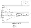
- the first magnet array 126 and the second magnet array 128 are configured so that the sum of the attractive force of the magnets arranged to attract one another and the repulsive force of the magnets arranged to repel one another varies according to the separation distance between the first array 126 and the second array 128.
- FIG. 4 illustrates the attractive force vs. separation distance for the magnets arranged to attract (curve A), the repulsive force vs. separation distance for the magnets arranged to repel (curve R), and the net attractive or repulsive force of all of the magnets vs. distance (curve T).
- the clutch assembly 100 also has an electromagnet 130 in the form of a coil of wire 132 wrapped around a portion of the input shaft 102 adjacent to the actuation sleeve 114.
- the electromagnet 130 can be energized by driving current in a first direction, which generates a magnetic field that repels the first array 126 of magnets with a force greater than the repulsive force between the first array 126 and second array 128 of magnets.
- the electromagnet 130 can be energized by driving current in a second opposite direction, which generates a magnetic field that attracts the first array of magnets 126 with a force greater than the attractive force between the first array 126 and the second array 128. This tends to pull the actuation sleeve to the second position ( FIG. 3 ).
- the torque sensing circuit may include one or more of a current sensor, a position sensor, a torque transducer, a force sensor, etc.
- the torque sensing circuit is similar to the electronic clutch circuit described in commonly owned U.S. Patent Application No. 13/798,210, filed March 13, 2013 , which is incorporated by reference.
- the control circuit may receive an input signal from a position sensing circuit 148, which corresponds the current position of the actuation sleeve 118 (e.g., via a Hall effect sensor or a membrane potentiometer).
- the controller processes the torque setting input signal, the torque sensing input signal, and the position sensing input signal to determine when and in which direction to cause the drive circuit to energize the electromagnet to change the position of the actuation sleeve 118.
- the control circuit receives an input signal from the torque setting circuit that corresponds to the desired torque setting.
- the control circuit receives an input signal from the torque sensing circuit that indicates the output torque.
- the control circuit receives an input signal from the position sensing circuit that indicates whether the actuation sleeve 118 is in the first position or the second position.
- the control circuit determines whether the sensed torque has exceeded the desired threshold torque, which indicates that torque transmission should be interrupted. If YES, then at step 158, the control circuit determines whether the actuator is already in the second position ( FIG. 3 ), in which torque transmission is interrupted. If YES, then control circuit returns to step 150.
- control circuit causes the drive circuit to momentarily drive the electromagnet to attract the actuator from the first position to the second position to interrupt torque transmission.
- the actuator Once the actuator is in the second position, current need not be delivered to the electromagnetic coil to keep the actuator in the second position, as the repulsive force between the first and second magnet arrays will keep the actuator in the second position. By requiring only a momentary burst of current, this saves energy and drain on a battery (if a cordless tool).
- step 156 the control circuit determines that the sensed torque does not exceed the torque setting, this indicates that torque transmission should be permitted.
- step 158 the control circuit determines whether the actuator is already in the first position ( FIG. 2 ), in which torque transmission is permitted. If YES, then control circuit returns to step 150. If NO, then the control circuit causes the drive circuit to momentarily drive the electromagnet to repel the actuator away from the second position to the first position to allow torque transmission. Once the actuator is in the first position, current need not be delivered to the electromagnetic coil to keep the in the second position, as the attractive force between the first and second magnet arrays will keep the actuatorin the second position. By requiring only a momentary burst of current, this saves energy and drain on a battery (if a cordless tool).
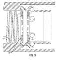
- a mode change mechanism in the form of an electromagnetic clutch assembly 700 may replace the torque clutch assembly in the power tool disclosed in the above-referenced U.S. Patent No. 7,452,304 .
- the clutch assembly 700 includes a ring gear 702 of the planetary transmission, and a positioning member in the form of a generally cylindrical transmission housing 704.
- the transmission housing 704 receives the ring gear 702 and other gears of the planetary gear transmission (not shown), and is fixedly received in a tool housing 706.
- the transmission housing 704 includes a plurality of radial bores 710 that receive a plurality of drive balls 712.
- the ring gear 702 has a plurality of longitudinal grooves 713 that receive the drive balls 712.
- the actuation sleeve 714 has a base wall 719 that includes a first array of magnets 726, and the transmission housing 704 has a second array of magnets 728 that are arranged similarly to the first array of magnets 126 and the second array of magnets 128 described above with respect to FIGS. 1-4 . Therefore, the first magnet array 726 and the second magnet array 728 are configured so that the net magnetic force is strongly positive (attractive) when the separation distance is less than a predetermined threshold (e.g., 1 mm), and the net magnetic force is weakly negative (repulsive) when the separation distance is greater than the predetermined threshold.
- a predetermined threshold e.g. 1 mm
- the clutch assembly 700 also has an electromagnet 730 in the form of a coil of wire 732 adjacent to the actuation sleeve 714, similar to the electromagnet 130 described above with respect to FIGS. 1-4 .
- the electromagnet 730 can be momentarily energized by driving current in a first direction, to push the actuation sleeve 714 to the first position ( FIG. 8 ).
- the electromagnet 730 can be momentarily energized by driving current in a second opposite direction, to pull the actuation sleeve 714 to the second position ( FIG. 9 ).
- the electromagnet 730 may be coupled to a similar electronics module as the electronics module 138 illustrated in FIG. 5 and described above.
- the clutch assembly 700 may be operated according to the method illustrated in FIG. 6 and described above.
- the speed reduction ratio of a multi-speed planetary transmission may be changed by selectively preventing rotation of one or more of the ring gears (which results in a greater speed reduction) or allowing rotation of one or more of the ring gears (which results in a lesser speed reduction). Therefore, the clutch assembly 700 could instead be connected to a controller that receives an input of a speed setting signal that corresponds to a desired speed setting of the tool. When the speed setting signal changes, indicating that the desired speed reduction ratio has changed, the electromagnet 730 can be driven to move the actuation sleeve 714 to either the first or second position to change the speed reduction ratio of the transmission accordingly.
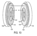
- an actuator 1020 may be moveable between first and second positions and a positioning member 1022 may remain stationary relative to the actuation 1020.
- the actuator 1020 may have a first magnet array 1026 (which is a substitute for the above-described magnet arrays 126, 726) and the positioning member 1022 may have a second magnet array 1028 (which is a substitute for the above-described magnet arrays 128, 728).
- the first magnet array 1026 includes a first inner ring magnet 1032 and a first outer ring magnet 1030 concentrically mounted on a first non-magnetic backer plate 1034.
- the actuator 1020 and the positioning member 1022 may be used in conjunction with an electromagnet (not shown) in the manner discussed above with respect to FIGS. 1-9 to enable movement of the actuator between the first and second positions for first and second modes of operation when the electromagnet is energized, and allows the actuator to be retained in one of the first and second positions when the electromagnet is not energized.
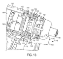
- a power tool such as a drill/driver 1180 includes a mode change mechanism in the form of an electromagnetic clutch assembly 1100.
- the power tool 1180 includes a housing 1182 having a motor housing 1181, a handle 1182 extending downward from the motor housing 1181, and a transmission housing 1184 coupled to a front end of the motor housing 1181.
- the handle 1182 is coupleable to a removable battery pack 1186, although it should be understood that the battery could be integral, or the housing could be coupled to an alternative source of electrical power such as an AC power source.
- the electromagnetic clutch assembly 1100 includes an output stage ring gear 1102 of the transmission 1192, the output spindle 1104, and an axially moveable actuator in the form of an actuator sleeve 1106.
- the ring gear meshes with a plurality of planet gears (not shown) which are carried by an output stage planet carrier 1108.
- the carrier 1108 is non-rotationally coupled with the output spindle 1104.
- the planet gears also mesh with an input sun gear (not shown) that extends from the motor or from a previous stage of the transmission.
- the teeth 1116 of the actuator 1106 engage the slots 1110 in the ring gear 1102, preventing rotation of the ring gear, which allows torque to be transmitted from the transmission to the output spindle 1104.
- the teeth 1116 of the actuator 1106 do not engage the slots 1110 in the ring gear 1102, which allows the ring gear 1102 to rotate, thus interrupting torque transmission to the output spindle 1104.
- the actuation sleeve 1106 includes a ring-shaped permanent magnet 1118 coupled to the ring portion 1112 of the actuation sleeve 1106.
- a first positioning member 1125 having a first ferromagnetic ring 1126 and a first ring-shaped electromagnet 1128.
- a second positioning member 1127 having a second ferromagnetic ring 1120 and a second ring-shaped electromagnet 1122.
- the actuation sleeve 1106 tends to stay in the first position due to the attractive force between the ring magnet 1118 and the first ferromagnetic ring 1126 being greater than the attractive force between the ring magnet 1118 and the second ferromagnetic ring 1120 (due to the closer proximity to the first ferromagnetic ring 1120).
- the first electromagnet 1128 can be momentarily energized to create a repulsive force against the ring magnet 1118 and/or the second electromagnet 1120 can be momentarily energized to generate an attractive force with the ring magnet 1118, with the sum of these forces being greater than the attractive force between the ring magnet 1118 and the first ferromagnetic ring 1126. Once these forces cause the actuator sleeve 1106 to move to the second position ( FIG.
- the electromagnets 1122, 1128 can be de-energized, and the actuator sleeve 1106 will remain in the second position due to the attractive force between the ring magnet 1118 with the second ferromagnetic ring 1120 being greater than the attractive force between the ring magnet 1118 and the first ferromagnetic ring (due to closer proximity to the second ferromagnetic ring 1120).
- the first electromagnet 1128 can be momentarily energized to create an attractive force with the ring magnet 1118 and/or the second electromagnet 1120 can be momentarily energized to generate a repulsive force against the ring magnet 1118, with the sum of these forces being greater than the attractive force between the ring magnet 1118 and the second ferromagnetic ring 1120.
- the electromagnets 1122, 1128 can be de-energized, and the actuator sleeve 1106 will remain in the first position, as discussed above.
- the transmission housing may also include mechanical stops 1130 and 1132 in front of each of the ferromagnetic rings 1120, 1126 to prevent complete contact between the ring magnet 1118 and the ferromagnetic rings 1120, 1126, in order to require less force to move the actuator sleeve 1106 between the first and second positions.
- the electromagnets 1122, 1128 each may be coupled to an electronics module 1150 that includes a driver circuit 1152 (e.g., an H-bridge circuit) configured to drive the electromagnets 1122, 1128.
- the driver circuit 1158 may be connected to the output of the control circuit 1188 (e.g., a microprocessor or controller).
- the control circuit 1188 may receive an input from a torque setting circuit 1154 that generates a signal corresponding to a desired torque setting.
- the desired torque setting may be input from a user interface 1148 (e.g., buttons or electronic controls) coupled to the housing.
- the control circuit 1188 may also receive an input from a torque sensing circuit 1156 that generates a signal that corresponds to the amount of output torque on the tool.
- the torque sensing circuit 1156 may include one or more of a current sensor, a position sensor, a torque transducer, a force sensor, etc.
- the torque sensing circuit is similar to the electronic clutch circuit described in the aforementioned commonly owned U.S. Patent Application No. 13/798,210, filed March 13, 2013 , which is incorporated by reference.
- the control circuit 1188 may also receive an input from a distance setting circuit 1160.
- the distance setting circuit 1160 that generates a signal corresponding to a desired distance from the workpiece at which the electromagnetic clutch should interrupt torque transmission.
- the desired distance setting may be input from the user interface 1148.
- the control circuit 1188 also receives an input from a distance sensing circuit 1146 that generates a signal that corresponds to a sensed distance between the tool and the workpiece.
- the distance sensing circuit is coupled to a proximity sensor system 1140 that includes a optical generator (e.g., an LED, light or laser generator) 1142 and an optical detector 1144.
- a proximity sensor system 1140 that includes a optical generator (e.g., an LED, light or laser generator) 1142 and an optical detector 1144.
- the distance sensing circuit 1146 Based on input from the optical detector 1144 corresponding to the intensity of light reflected from the workpiece, the distance sensing circuit 1146 generates a signal that corresponds to the sensed distance from the workpiece.
- Other optical and non-contact devices may be used to sense distance from a workpiece.
- the user interface may also enable the user to select between a distance sensing mode of operation and a torque sensing mode of operation.
- the control circuit may receive an input signal from a position sensing circuit 1158, which corresponds the current position of the actuation sleeve 1106 (e.g., via a Hall effect sensor or a membrane potentiometer).
- the controller processes the torque setting input signal, the torque sensing input signal, the distance setting input signal, the distance sensing input signal, and the position sensing input signal to determine when and in which direction to cause the drive circuit to energize the electromagnets to change the position of the actuation sleeve 1106.
- the control circuit first receives a user input of whether to use the distance sensing mode or the torque sensing mode. If the distance sensing mode is selected, the control circuit performs the steps illustrated in FIG. 16B , as described below. If the torque sensing mode is selected, then at step 1201, the control circuit receives the input signal from the torque setting circuit that corresponds to the desired torque setting. At step 1202, the control circuit receives the input signal from the torque sensing circuit that indicates the output torque. At step 1204, the control circuit receives the input signal from the position sensing circuit that indicates whether the actuator is in the first position or the second position.
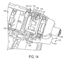
- the control circuit determines whether the sensed torque has exceeded the desired threshold torque, which indicates that torque transmission should be interrupted. If YES, then at step 1208, the control circuit determines whether the actuator is already in the second position ( FIG. 14 ), in which torque transmission is interrupted. If YES, then control circuit returns to step 1201. If NO, then at step 1210, the control circuit causes the drive circuit to momentarily drive the electromagnets to move the actuator sleeve from the first position to the second position to interrupt torque transmission. Once the actuator sleeve is in the second position, current need not be delivered to the electromagnets to keep the actuator sleeve in the second position, as the attractive force between the permanent magnet ring and the second ferromagnetic ring will do this. By requiring only a momentary burst of current, this saves energy and drain on a battery (if a cordless tool).
- control circuit determines whether the actuator is already in the first position ( FIG. 13 ), in which torque transmission is permitted. If YES, then control circuit returns to step 1201. If NO, then, at step 1214, the control circuit causes the drive circuit to momentarily drive the electromagnets to move the actuator sleeve away from the second position to the first position to allow torque transmission.
- the control circuit receives the input signal from the distance setting circuit that corresponds to the desired distance setting for when to interrupt torque transmission.
- the control circuit receives the input signal from the distance sensing circuit that indicates the sensed distance of the tool holder from the workpiece.
- the control circuit receives the input signal from the position sensing circuit that indicates whether the actuator sleeve is in the first position or the second position.
- the control circuit determines whether the sensed distance is less than the desired threshold distance, which indicates that torque transmission should be interrupted.
- the control circuit determines whether the actuator is already in the second position ( FIG. 14 ), in which torque transmission is interrupted. If YES, then control circuit returns to step 1301. If NO, then at step 1310, the control circuit causes the drive circuit to momentarily drive the electromagnets to move the actuator sleeve from the first position to the second position to interrupt torque transmission. Once the actuator sleeve is in the second position, current need not be delivered to the electromagnets to keep the actuator sleeve in the second position, as the attractive force permanent magnet ring and the second ferromagnetic ring will do this. By requiring only a momentary burst of current, this saves energy and drain on a battery (if a cordless tool).
- a power tool such as an impact wrench 1710 includes an electromagnetic mode change mechanism in the form of an electromagnetically actuatable socket holder 1720.
- the impact wrench 1710 includes a housing 1712 having a handle 1714, a trigger mechanism 1716 for activating the impact wrench 1710, and a cover 1760 at a front of the housing 1712.
- a base 1715 of the handle 1714 is adapted to receive a battery pack (not shown) for use as a cordless impact wrench. It should be understood that the present disclosure can also be applied to pneumatic, hydraulic and corded electrical impact wrench devices.
- the impact wrench includes a motor 1711 disposed within the housing 1712 that drives a transmission and impact mechanism 1713, which in turn drives an anvil 1718 extending from the front end of the housing 1712, as is generally known in the art, and as described in the aforementioned U.S. Patent Application No. 13/494,325 .
- the anvil 1718 includes a square socket drive 1718a that is designed to drive a socket wrench (not shown).
- the mode change mechanism in the form of the electromagnetically actuatable socket holder 1720 is configured to selectively retain a socket wrench on the square drive 1718a.
- the socket holder 1720 includes a radially extending and retractable retainer pin 1724 configured to engage the socket wrench when it is coupled to the square socket drive 1718a.
- the retainer pin 1724 is received in a radial aperture 1723 in a distal end of the square socket drive 1718a.
- a lever pin 1730 is received in an axially extending bore 1732 provided in the anvil 1718.
- the lever pin 1730 has a rear end portion with a partially spherical pivot end 1750 received in a concave partially conical bore portion 1732a of the bore 1732.
- the lever pin 1730 also has a front end portion that engages a transverse aperture 1734 provided in the retention pin 1724.
- the lever pin 1730 has a mid portion that engages a transverse aperture in an actuator pin 1748.
- the actuator pin 1748 is received in a transverse bore 1727 in a proximal portion of the anvil 1718.
- the actuator pin 1748 is biased to a radially outward direction by a spring 1726 that is received in the transverse bore 1727.
- an actuator in the form of an axially moveable cam ring 1740, a first positioning member in the form of an axially stationary forward ring 1762, and a second positioning member in the form of an axially stationary rearward ring 1764.
- the cam ring 1740 has an inner cam surface 1746 disposed against an outer cam surface 1744 of the actuator pin 1748.
- the cam ring is moveable between a forward position for a first mode of operation ( FIG. 18A ) and a rearward position for a second mode of operation ( FIG. 18B ).
- the forward ring 1762 includes a forward electromagnetic coil 1766 disposed in a first annular ferromagnetic (e.g., steel) cup 1768.
- the rearward ring 1764 includes a rearward electromagnetic coil 1770 disposed in a second annular ferromagnetic (e.g., steel) cup 1772.
- the cam ring 1740 is disposed between the forward and rearward rings 1762, 1764 and includes an integral permanent magnet ring 1742.
- the forward and rearward electromagnetic coils 1766, 1770 may be selectively energized to move the cam ring 1740 between its forward or rearward position.
- the front electromagnet 1766 can be momentarily energized to create a repulsive force against the ring magnet 1742 and/or the rear electromagnet 1770 can be momentarily energized to generate an attractive force with the ring magnet 1742, with the sum of these forces being greater than the attractive force between the ring magnet 1742 and the first ferromagnetic cup 1768. Once these forces cause the cam ring 1742 to move to the rearward position ( FIG.
- the electromagnets 1766, 1770 can be de-energized, and the cam ring 1742 will remain in the rearward position due to the attractive force between the ring magnet 1742 with the second ferromagnetic cup 1772 being greater than the attractive force between the ring magnet 1742 and the first ferromagnetic cup 1768 (due to closer proximity to the second ferromagnetic cup 1772).
- the forward electromagnet 1766 can be momentarily energized to create an attractive force with the ring magnet 1742 and/or the rearward electromagnet 1770 can be momentarily energized to generate a repulsive force against the ring magnet 1742, with the sum of these forces being greater than the attractive force between the ring magnet 1742 and the rearward ferromagnetic cup 1772.
- the electromagnets 1766, 1770 can be de-energized, and the cam ring 1740 will remain in the forward position due to the attractive force between the ring magnet 1742 and the first ferromagnetic cup 1768 being greater than the attractive force between the ring magnet 1742 and the second ferromagnetic cup 1772 (due to the closer proximity to the first ferromagnetic cup 1768).
- the permanent magnet 1742 is attracted to the first annular cup 1768 if in the forward position, or the second annular cup 1772 if in the second position.
- a pulse of energy is required to change the position of the cam ring 1740 and thus the mode of operation.
- Continuous power is not required to hold the cam ring in either the forward or rearward position and this is advantageous for energy conservation on a cordless tool.
- the electromagnetically actuatable socket holder 1720 can be operated using a single coil and a spring for biasing the cam ring away from the coil during a non-activated state.
- the cover 1760 may also include mechanical stops (not shown) between each of the ferromagnetic cups 1768, 1772 and the ring magnet 1742 to prevent complete contact between the ring magnet 1742 and the ferromagnetic cups 1768, 1768, in order to require less force to move the cam ring 1740 between the forward and rearward positions.
- the cam surface 1746 of the cam ring 1724 engages the cam surface 1744 of the actuator pin 1748, causing the actuator pin 1748 to move downward in the bore 1727 in the anvil 1718 against the biasing force of the spring 1726.
- the lever pin 1732 pivots in a counter clockwise direction CCW about pivot end 1750, causing the retainer pin 1724 to be moved radially inward to a retracted or release position.
- cam ring 1724 moves to its forward axial position in the first mode of operation ( FIG. 18A )
- the spring 1726 causes the actuator pin 1748 to move upward. causing the lever pin 1730 to rotate in a clockwise direction CW so that the retainer pin 1724 extends in an engaged position.
- the first and second electromagnetic coils 1766, 1770 can be electrically connected to the tool battery or an alternative power source such as an A/C power source by a control circuit, such as one of the control circuits described above.
- a user-actuatable switch for controlling movement of the cam ring 1740 by the electromagnets can be placed at one or more of multiple different locations on the power tool 1710, as indicated by the X's in FIG. 17 .
- the socket release mechanism can be controlled from virtually any location on the tool. It should be understood that this type of electromechanical socket release mechanism can be used with any of the other disclosed embodiments for a socket release mechanism described in U.S. Patent Application No. 13/494,325 .
Landscapes
- Engineering & Computer Science (AREA)
- Mechanical Engineering (AREA)
- Portable Power Tools In General (AREA)
- Drilling And Boring (AREA)
Priority Applications (1)
| Application Number | Priority Date | Filing Date | Title |
|---|---|---|---|
| EP16160612.4A EP3056314B1 (de) | 2013-03-13 | 2014-03-10 | Elektromagnetischer modusumschaltvorrichtungsmechanismus für elektrowerkzeuge |
Applications Claiming Priority (1)
| Application Number | Priority Date | Filing Date | Title |
|---|---|---|---|
| US13/799,177 US20130192860A1 (en) | 2011-06-24 | 2013-03-13 | Electromagnetic mode change mechanism for power tool |
Related Child Applications (1)
| Application Number | Title | Priority Date | Filing Date |
|---|---|---|---|
| EP16160612.4A Division EP3056314B1 (de) | 2013-03-13 | 2014-03-10 | Elektromagnetischer modusumschaltvorrichtungsmechanismus für elektrowerkzeuge |
Publications (1)
| Publication Number | Publication Date |
|---|---|
| EP2777883A1 true EP2777883A1 (de) | 2014-09-17 |
Family
ID=50239464
Family Applications (2)
| Application Number | Title | Priority Date | Filing Date |
|---|---|---|---|
| EP16160612.4A Active EP3056314B1 (de) | 2013-03-13 | 2014-03-10 | Elektromagnetischer modusumschaltvorrichtungsmechanismus für elektrowerkzeuge |
| EP14158587.7A Withdrawn EP2777883A1 (de) | 2013-03-13 | 2014-03-10 | Nuss-Haltevorrichtung |
Family Applications Before (1)
| Application Number | Title | Priority Date | Filing Date |
|---|---|---|---|
| EP16160612.4A Active EP3056314B1 (de) | 2013-03-13 | 2014-03-10 | Elektromagnetischer modusumschaltvorrichtungsmechanismus für elektrowerkzeuge |
Country Status (1)
| Country | Link |
|---|---|
| EP (2) | EP3056314B1 (de) |
Cited By (3)
| Publication number | Priority date | Publication date | Assignee | Title |
|---|---|---|---|---|
| WO2019137578A1 (de) * | 2018-01-12 | 2019-07-18 | STAHLWILLE Eduard Wille GmbH & Co. KG | Drehmomentwerkzeug |
| CN112220575A (zh) * | 2020-11-11 | 2021-01-15 | 慈溪赛嘉电子有限公司 | 电动牙刷及其驱动机构 |
| US11618138B2 (en) | 2018-01-12 | 2023-04-04 | STAHLWILLE Eduard Wille GmbH & Co. KG | Release mechanism for a torque tool |
Families Citing this family (2)
| Publication number | Priority date | Publication date | Assignee | Title |
|---|---|---|---|---|
| US11097404B2 (en) | 2016-11-11 | 2021-08-24 | Zimmer Biomet Spine, Inc. | Tool torque limiter |
| DE102022002785A1 (de) * | 2022-07-28 | 2024-02-08 | Hochschule für Angewandte Wissenschaften Hamburg Körperschaft des Öffentlichen Rechts | Werkzeug für die Schraubenmontage mit Magnetsensor-Array zur Torsions-Messung |
Citations (7)
| Publication number | Priority date | Publication date | Assignee | Title |
|---|---|---|---|---|
| US7452304B2 (en) | 2001-01-23 | 2008-11-18 | Black & Decker Inc. | Multispeed power tool transmission |
| US7717192B2 (en) | 2007-11-21 | 2010-05-18 | Black & Decker Inc. | Multi-mode drill with mode collar |
| US7750778B2 (en) | 2008-04-04 | 2010-07-06 | Cedar Ridge Research, Llc | System and method for attachment of objects |
| US20110152029A1 (en) | 2009-12-23 | 2011-06-23 | Scott Rudolph | Hybrid impact tool with two-speed transmission |
| US20120074658A1 (en) | 2009-05-05 | 2012-03-29 | Black & Decker Inc. | Power Tool with Integrated Bit Retention Device |
| EP2537639A1 (de) * | 2011-06-24 | 2012-12-26 | Black & Decker Inc. | Schnelllösbarer Bithalter für Schlagschrauber |
| US8347750B2 (en) | 2007-09-11 | 2013-01-08 | Black & Decker Inc. | Transmission and variable radially expanding spring clutch assembly |
Family Cites Families (3)
| Publication number | Priority date | Publication date | Assignee | Title |
|---|---|---|---|---|
| GB332379A (en) * | 1929-06-28 | 1930-07-24 | Edwin Lewis Connell | Screw-stud setting machines |
| GB701630A (en) * | 1951-07-17 | 1953-12-30 | Dillon Stevens | Gang apparatus for tightening a plurality of threaded fastening elements |
| DE3202420C2 (de) * | 1982-01-26 | 1990-03-29 | Deutsche Gardner-Denver GmbH, 7084 Westhausen | Schrauber |
-
2014
- 2014-03-10 EP EP16160612.4A patent/EP3056314B1/de active Active
- 2014-03-10 EP EP14158587.7A patent/EP2777883A1/de not_active Withdrawn
Patent Citations (8)
| Publication number | Priority date | Publication date | Assignee | Title |
|---|---|---|---|---|
| US7452304B2 (en) | 2001-01-23 | 2008-11-18 | Black & Decker Inc. | Multispeed power tool transmission |
| US8347750B2 (en) | 2007-09-11 | 2013-01-08 | Black & Decker Inc. | Transmission and variable radially expanding spring clutch assembly |
| US7717192B2 (en) | 2007-11-21 | 2010-05-18 | Black & Decker Inc. | Multi-mode drill with mode collar |
| US7750778B2 (en) | 2008-04-04 | 2010-07-06 | Cedar Ridge Research, Llc | System and method for attachment of objects |
| US20120074658A1 (en) | 2009-05-05 | 2012-03-29 | Black & Decker Inc. | Power Tool with Integrated Bit Retention Device |
| US20110152029A1 (en) | 2009-12-23 | 2011-06-23 | Scott Rudolph | Hybrid impact tool with two-speed transmission |
| EP2537639A1 (de) * | 2011-06-24 | 2012-12-26 | Black & Decker Inc. | Schnelllösbarer Bithalter für Schlagschrauber |
| US20120325509A1 (en) | 2011-06-24 | 2012-12-27 | Black & Decker Inc. | Quick Release Socket Attachment For Impact Wrench |
Cited By (6)
| Publication number | Priority date | Publication date | Assignee | Title |
|---|---|---|---|---|
| WO2019137578A1 (de) * | 2018-01-12 | 2019-07-18 | STAHLWILLE Eduard Wille GmbH & Co. KG | Drehmomentwerkzeug |
| JP2021510124A (ja) * | 2018-01-12 | 2021-04-15 | シュタールヴィレ エドゥアルド ヴィレ ゲゼルシャフト ミット ベシュレンクテル ハフツング ウント コンパニー コマンディートゲゼルシャフトSTAHLWILLE Eduard Wille GmbH & Co. KG | トルク工具 |
| US11518010B2 (en) | 2018-01-12 | 2022-12-06 | STAHLWILLE Eduard Wille GmbH & Co. KG | Torque tool |
| TWI791702B (zh) * | 2018-01-12 | 2023-02-11 | 德商達威力愛德威利有限兩合公司 | 栓密器 |
| US11618138B2 (en) | 2018-01-12 | 2023-04-04 | STAHLWILLE Eduard Wille GmbH & Co. KG | Release mechanism for a torque tool |
| CN112220575A (zh) * | 2020-11-11 | 2021-01-15 | 慈溪赛嘉电子有限公司 | 电动牙刷及其驱动机构 |
Also Published As
| Publication number | Publication date |
|---|---|
| EP3056314A1 (de) | 2016-08-17 |
| EP3056314B1 (de) | 2021-05-05 |
Similar Documents
| Publication | Publication Date | Title |
|---|---|---|
| US12365076B2 (en) | Electromagnetic actuator for power tool | |
| EP3056314B1 (de) | Elektromagnetischer modusumschaltvorrichtungsmechanismus für elektrowerkzeuge | |
| CN210307664U (zh) | 一种旋转动力工具 | |
| EP2248633B1 (de) | Elektrowerkzeug mit integrierter Bohrkronenrückhaltevorrichtung | |
| US9364942B2 (en) | Quick release socket attachment for impact wrench | |
| US8763722B2 (en) | Power tool having clutch device | |
| CN101189094B (zh) | 动力驱动器和用于动力驱动器的电子离合器 | |
| EP1762343A2 (de) | Schlag-Rotations-Werkzeug mit Bohrmodus | |
| CN103459098B (zh) | 电动工具 | |
| JP2004291138A (ja) | 磁気インパクト工具 | |
| CA2619977A1 (en) | Power tool | |
| WO2013089795A1 (en) | Rotary hammer | |
| US20240208024A1 (en) | Power tool | |
| CN109695637A (zh) | 包括电磁离合器的电动工具 | |
| JP4897998B2 (ja) | 動力ナットランナー | |
| EP3034243B1 (de) | Bohrhammer | |
| JP2011047465A (ja) | 回転電動工具の自動変速装置 | |
| CN103659748B (zh) | 电动工具 | |
| CN102126034B (zh) | 电动工具 | |
| CN201664773U (zh) | 电动工具 | |
| CA3061692A1 (en) | Electromechanical gear selection device comprising a stepping motor | |
| JP5379606B2 (ja) | 回転電動工具の自動変速装置 | |
| EP2883661B1 (de) | Bohrhammer | |
| JP5290720B2 (ja) | 2位置切替え装置 | |
| WO2025237675A1 (en) | Power tool and two-speed gear assembly for a power tool |
Legal Events
| Date | Code | Title | Description |
|---|---|---|---|
| 17P | Request for examination filed |
Effective date: 20140310 |
|
| AK | Designated contracting states |
Kind code of ref document: A1 Designated state(s): AL AT BE BG CH CY CZ DE DK EE ES FI FR GB GR HR HU IE IS IT LI LT LU LV MC MK MT NL NO PL PT RO RS SE SI SK SM TR |
|
| AX | Request for extension of the european patent |
Extension state: BA ME |
|
| PUAI | Public reference made under article 153(3) epc to a published international application that has entered the european phase |
Free format text: ORIGINAL CODE: 0009012 |
|
| R17P | Request for examination filed (corrected) |
Effective date: 20150204 |
|
| RBV | Designated contracting states (corrected) |
Designated state(s): AL AT BE BG CH CY CZ DE DK EE ES FI FR GB GR HR HU IE IS IT LI LT LU LV MC MK MT NL NO PL PT RO RS SE SI SK SM TR |
|
| 17Q | First examination report despatched |
Effective date: 20151216 |
|
| STAA | Information on the status of an ep patent application or granted ep patent |
Free format text: STATUS: THE APPLICATION IS DEEMED TO BE WITHDRAWN |
|
| 18D | Application deemed to be withdrawn |
Effective date: 20160628 |