EP2777891B1 - Embrayage pour outil électrique - Google Patents
Embrayage pour outil électrique Download PDFInfo
- Publication number
- EP2777891B1 EP2777891B1 EP14160009.8A EP14160009A EP2777891B1 EP 2777891 B1 EP2777891 B1 EP 2777891B1 EP 14160009 A EP14160009 A EP 14160009A EP 2777891 B1 EP2777891 B1 EP 2777891B1
- Authority
- EP
- European Patent Office
- Prior art keywords
- clutch
- spring
- housing
- spring retainer
- gear
- Prior art date
- Legal status (The legal status is an assumption and is not a legal conclusion. Google has not performed a legal analysis and makes no representation as to the accuracy of the status listed.)
- Active
Links
Images





Classifications
-
- F—MECHANICAL ENGINEERING; LIGHTING; HEATING; WEAPONS; BLASTING
- F16—ENGINEERING ELEMENTS AND UNITS; GENERAL MEASURES FOR PRODUCING AND MAINTAINING EFFECTIVE FUNCTIONING OF MACHINES OR INSTALLATIONS; THERMAL INSULATION IN GENERAL
- F16D—COUPLINGS FOR TRANSMITTING ROTATION; CLUTCHES; BRAKES
- F16D7/00—Slip couplings, e.g. slipping on overload, for absorbing shock
-
- B—PERFORMING OPERATIONS; TRANSPORTING
- B25—HAND TOOLS; PORTABLE POWER-DRIVEN TOOLS; MANIPULATORS
- B25F—COMBINATION OR MULTI-PURPOSE TOOLS NOT OTHERWISE PROVIDED FOR; DETAILS OR COMPONENTS OF PORTABLE POWER-DRIVEN TOOLS NOT PARTICULARLY RELATED TO THE OPERATIONS PERFORMED AND NOT OTHERWISE PROVIDED FOR
- B25F5/00—Details or components of portable power-driven tools not particularly related to the operations performed and not otherwise provided for
- B25F5/001—Gearings, speed selectors, clutches or the like specially adapted for rotary tools
-
- B—PERFORMING OPERATIONS; TRANSPORTING
- B25—HAND TOOLS; PORTABLE POWER-DRIVEN TOOLS; MANIPULATORS
- B25B—TOOLS OR BENCH DEVICES NOT OTHERWISE PROVIDED FOR, FOR FASTENING, CONNECTING, DISENGAGING OR HOLDING
- B25B23/00—Details of, or accessories for, spanners, wrenches, screwdrivers
- B25B23/14—Arrangement of torque limiters or torque indicators in wrenches or screwdrivers
- B25B23/141—Mechanical overload release couplings
-
- F—MECHANICAL ENGINEERING; LIGHTING; HEATING; WEAPONS; BLASTING
- F16—ENGINEERING ELEMENTS AND UNITS; GENERAL MEASURES FOR PRODUCING AND MAINTAINING EFFECTIVE FUNCTIONING OF MACHINES OR INSTALLATIONS; THERMAL INSULATION IN GENERAL
- F16D—COUPLINGS FOR TRANSMITTING ROTATION; CLUTCHES; BRAKES
- F16D7/00—Slip couplings, e.g. slipping on overload, for absorbing shock
- F16D7/04—Slip couplings, e.g. slipping on overload, for absorbing shock of the ratchet type
- F16D7/06—Slip couplings, e.g. slipping on overload, for absorbing shock of the ratchet type with intermediate balls or rollers
- F16D7/08—Slip couplings, e.g. slipping on overload, for absorbing shock of the ratchet type with intermediate balls or rollers moving axially between engagement and disengagement
-
- B—PERFORMING OPERATIONS; TRANSPORTING
- B23—MACHINE TOOLS; METAL-WORKING NOT OTHERWISE PROVIDED FOR
- B23B—TURNING; BORING
- B23B2260/00—Details of constructional elements
- B23B2260/044—Clutches
- B23B2260/0445—Overload clutches
-
- B—PERFORMING OPERATIONS; TRANSPORTING
- B23—MACHINE TOOLS; METAL-WORKING NOT OTHERWISE PROVIDED FOR
- B23B—TURNING; BORING
- B23B45/00—Hand-held or like portable drilling machines, e.g. drill guns; Equipment therefor
- B23B45/008—Gear boxes, clutches, bearings, feeding mechanisms or like equipment
-
- B—PERFORMING OPERATIONS; TRANSPORTING
- B25—HAND TOOLS; PORTABLE POWER-DRIVEN TOOLS; MANIPULATORS
- B25D—PERCUSSIVE TOOLS
- B25D2250/00—General details of portable percussive tools; Components used in portable percussive tools
- B25D2250/165—Overload clutches, torque limiters
-
- F—MECHANICAL ENGINEERING; LIGHTING; HEATING; WEAPONS; BLASTING
- F16—ENGINEERING ELEMENTS AND UNITS; GENERAL MEASURES FOR PRODUCING AND MAINTAINING EFFECTIVE FUNCTIONING OF MACHINES OR INSTALLATIONS; THERMAL INSULATION IN GENERAL
- F16H—GEARING
- F16H35/00—Gearings or mechanisms with other special functional features
- F16H35/10—Arrangements or devices for absorbing overload or preventing damage by overload
Definitions
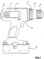
- a power tool in an aspect, includes a housing, a motor disposed in the housing, an output spindle received at least partially in the housing, and a transmission disposed in the housing.
- the transmission is configured to selectively transmit torque from the motor to the output spindle.
- a clutch assembly is disposed between the transmission and the output spindle.
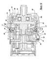
- the clutch assembly includes a clutch adjustment ring configured to move axially relative to the housing while being rotated relative to the housing.
- a spring retainer is disposed axially rearward of the clutch adjustment ring, is coupled for rotation together with the clutch adjustment ring, and is configured to remain substantially axially stationary relative to the housing when rotated.
- a spring is disposed between the clutch adjustment ring and the spring retainer.
- a clutch face is coupled to a portion of the transmission.
- the transmission assembly 16 is housed in the transmission cavity 42 and includes a speed selector mechanism 60.
- the transmission assembly 16 receives a rotary input from the motor pinion 46 and converts that input to a relatively lower speed, higher torque output that is transmitted to the shaft 62 of the output spindle assembly 20.
- the transmission assembly 16 includes a plurality of reduction elements that are selectively engaged by the speed selector mechanism 60 to provide a plurality of speed ratios. Each of the speed ratios multiplies the speed and torque of the drive input in a predetermined manner, permitting the output speed and torque of the transmission assembly 16 to be varied in a desired manner between a relatively low speed, high torque output and a relatively high speed, low torque output.
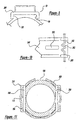
- a plurality of gear teeth 134c are formed into the outer perimeter of the body 134a and are sized to engage the gear teeth 152a of the second ring gear 152.
- the profile of the gear teeth 134c of the body 134a is illustrated in greater detail. As shown, each tooth 134c terminates at a gradual radius 190 at the forward face of the body 134a but terminates abruptly at the rearward face of the body 134a.
- a radius 192 is also formed on the valleys 194 between the gear teeth 134c.
- the second reduction carrier 154 includes a body 154a, which is formed in the shape of a flat cylinder, and plurality of pins 154b that extend from the rearward face of the body 154a.
- the rearward end of the bore 322 is sized to receive a forward portion of the gear case 100, the third ring gear 202 and the third reduction carrier 204, while the forward portion of the bore 322 is sized somewhat smaller so as to receive the coupling member 230 and the shaft 62 of the output spindle assembly 20.
- the nose portion 326 which is somewhat smaller in diameter than the base portion 324, is generally cylindrical, having a helical thread form 330 that wraps around its perimeter.
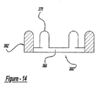
- the clutch plate 306 is illustrated to be a unitarily formed structure that includes a washer-like annular plate member 360 and a plurality of leg members 362 that are coupled to and circumferentially spaced about the annular plate member 360.
- the leg members 362 have a generally circular cross-section and extend generally perpendicularly from the plate member 360.
- the end of the each leg member 362 opposite the plate member 360 terminates in a spherical recess 364 that is configured to receive one of the balls 304, which are illustrated to be hardened bearing balls.
- the clutch plate 306' is illustrated to be similar to the clutch plate 306, except that the ends of the leg members 362' opposite the annular plate member 360 terminate at a spherical protrusion 370, rather than a spherical recess. Configuration in this manner is advantageous in that it eliminates the balls 304 from the clutch mechanism 18.
- the spring 308 is illustrated to be a conventional compression spring having ground ends.
- the spring 308 is disposed over the nose portion 326 of the clutch housing 300 between the adjustment ring 310 and the spring retainer 390.
- the adjustment ring 310 is an annular structure that is illustrated to include an internal annular flange 380, a threaded portion 382 and an engagement portion 384.
- the internal annular flange 380 extends around the inner circumference of the adjustment ring 310 and sized somewhat smaller in diameter than the spring 308 but larger than the nose portion 326 of the clutch housing 300.
- the third sun gear 200 causes the third set of planet gears 206 to rotate on their axes but not to oribit the sun gear 200 in any substantial manner.
- the third reduction carrier 204 substantially stops rotating, and torque transmission to the output spindle assembly 20 is greatly reduced and/or essentially interrupted.
Landscapes
- Engineering & Computer Science (AREA)
- Mechanical Engineering (AREA)
- General Engineering & Computer Science (AREA)
- Details Of Spanners, Wrenches, And Screw Drivers And Accessories (AREA)
Claims (11)
- Ensemble embrayage pour un outil électrique présentant un boîtier (12), une transmission (16) et un fuseau de sortie (20), l'ensemble embrayage comprenant :une bague de réglage d'embrayage (310) configurée pour se déplacer axialement par rapport au boîtier (12) tout en tournant par rapport au boîtier (12) ;un dispositif de retenue de ressort (390) disposé axialement vers l'arrière de la bague de réglage d'embrayage (310),un ressort (308) disposé entre la bague de réglage d'embrayage (310) et le dispositif de retenue de ressort (390) ;une face d'embrayage (222) accouplée à une partie de la transmission (16) ;un élément de verrouillage disposé entre le dispositif de retenue de ressort (390) et la face d'embrayage (222), l'élément de verrouillage (304, 370) étant configuré pour transférer une force de maintien exercée par le ressort (308) à la face d'embrayage (222),dans lequel un déplacement rotatif et axial de la bague de réglage d'embrayage (310) modifie la force de maintien exercée par le ressort (308), et lorsqu'une quantité de couple de sortie dépasse la force de maintien, la transmission de couple de la transmission (16) vers le fuseau de sortie (20) est effectivement interrompue ;caractérisé en ce que le dispositif de retenue de ressort (390) est accouplé pour rotation avec la bague de réglage d'embrayage (310) et configuré pour rester sensiblement axialement fixe par rapport au boîtier (2) lors de la rotation.
- Ensemble embrayage selon la revendication 1, comprenant en outre un boîtier d'embrayage (300) qui inclut une partie base vers l'arrière (324) configurée pour recevoir la face d'embrayage (222), et une partie nez (326) configurée pour recevoir au moins une partie du fuseau de sortie (20).
- Ensemble embrayage selon la revendication 2, dans lequel la partie nez (326) présente une partie extérieurement filetée (330), et la bague de réglage d'embrayage (310) est intérieurement filetée sur la partie extérieurement filetée (330).
- Ensemble embrayage selon la revendication 3, dans lequel le dispositif de retenue de ressort (390) est intérieurement non fileté et reçu sur la partie nez (326).
- Outil électrique comprenant :un boîtier (127) ;un moteur (14) disposé dans le boîtier ;un fuseau de sortie (20) reçu au moins partiellement dans le boîtier (12) ;une transmission (16) disposée dans le boîtier (12) et configurée pour transmettre sélectivement un couple du moteur (14) au fuseau de sortie (20) ;un ensemble embrayage (18) selon l'une quelconque des revendications 1 à 4, disposé entre la transmission (16) et le fuseau de sortie (20).
- Outil électrique selon la revendication 5, comprenant en outre un manchon de réglage d'embrayage (314) accouplé de manière non rotative à la bague de réglage d'embrayage (310) et au dispositif de retenue de ressort (390), de telle sorte qu'une rotation du manchon de réglage d'embrayage (314) entraîne une rotation de la bague de réglage d'embrayage (310) et du dispositif de retenue de ressort (390).
- Outil électrique selon la revendication 5, dans lequel la bague de réglage d'embrayage (310) présente une cavité (384) qui reçoit une première extrémité du ressort (308), et le dispositif de retenue de ressort (390) présente une seconde cavité (392) qui reçoit une seconde extrémité du ressort (308).
- Outil électrique selon la revendication 5, dans lequel le ressort (308) comprend l'un d'un ressort de compression et d'un ressort ondulé.
- Outil électrique selon la revendication 5, dans lequel l'ensemble embrayage comprend en outre une plaque d'embrayage (360) disposée entre le dispositif de retenue de ressort (390) et l'élément de verrouillage (304, 306), la plaque d'embrayage transférant la force de maintien du dispositif de retenue de ressort à l'élément de verrouillage.
- Outil électrique selon la revendication 5, dans lequel l'élément de verrouillage comprend au moins l'une d'une bille (304) et d'une broche (370), la face d'embrayage (222) comprend une surface inclinée, et la transmission de couple (16) de la transmission au fuseau de sortie (20) est effectivement interrompue lorsque le couple de sortie amène l'élément de verrouillage (304, 370) à glisser sur la surface inclinée (222).
- Outil électrique selon la revendication 5, dans lequel la transmission comprend un train planétaire présentant au moins une couronne dentée (202) et la face d'embrayage (222) est connectée à l'au moins une couronne dentée (202), de telle sorte que la transmission de couple est effectivement interrompue lorsque la couronne dentée (202) est autorisée à tourner par rapport au boîtier (12).
Applications Claiming Priority (1)
| Application Number | Priority Date | Filing Date | Title |
|---|---|---|---|
| US13/828,149 US9494200B2 (en) | 2013-03-14 | 2013-03-14 | Clutch for power tool |
Publications (2)
| Publication Number | Publication Date |
|---|---|
| EP2777891A1 EP2777891A1 (fr) | 2014-09-17 |
| EP2777891B1 true EP2777891B1 (fr) | 2020-07-15 |
Family
ID=50272516
Family Applications (1)
| Application Number | Title | Priority Date | Filing Date |
|---|---|---|---|
| EP14160009.8A Active EP2777891B1 (fr) | 2013-03-14 | 2014-03-14 | Embrayage pour outil électrique |
Country Status (2)
| Country | Link |
|---|---|
| US (1) | US9494200B2 (fr) |
| EP (1) | EP2777891B1 (fr) |
Cited By (1)
| Publication number | Priority date | Publication date | Assignee | Title |
|---|---|---|---|---|
| EP4387812A4 (fr) * | 2021-08-18 | 2025-06-18 | Milwaukee Electric Tool Corporation | Ensemble embrayage destiné à un outil électrique |
Families Citing this family (22)
| Publication number | Priority date | Publication date | Assignee | Title |
|---|---|---|---|---|
| US11059160B2 (en) | 2011-07-29 | 2021-07-13 | Black & Decker Inc. | Multispeed power tool |
| US20160121467A1 (en) * | 2014-10-31 | 2016-05-05 | Black & Decker Inc. | Impact Driver Control System |
| DE102014225903A1 (de) * | 2014-12-15 | 2016-06-16 | Robert Bosch Gmbh | Handwerkzeugvorrichtung |
| AU2016100188A4 (en) * | 2015-02-25 | 2016-04-07 | Chervon (Hk) Limited | Gardening tool and hedge trimmer |
| DE102015111570A1 (de) * | 2015-07-16 | 2017-01-19 | Jörg Hohmann | Drehschrauber |
| CN106641171B (zh) * | 2015-10-30 | 2021-06-11 | 苏州宝时得电动工具有限公司 | 变速工具 |
| US10406667B2 (en) * | 2015-12-10 | 2019-09-10 | Black & Decker Inc. | Drill |
| DE102016203886A1 (de) * | 2016-03-09 | 2017-09-14 | Robert Bosch Gmbh | Handwerkzeugmaschine mit einer Drehmomentkupplung |
| DE102017211779A1 (de) | 2016-07-11 | 2018-01-11 | Robert Bosch Gmbh | Handwerkzeugmaschinenvorrichtung |
| CN206795699U (zh) * | 2017-05-05 | 2017-12-26 | 南京德朔实业有限公司 | 扭力输出工具 |
| CN109834657B (zh) * | 2017-11-29 | 2021-01-19 | 南京德朔实业有限公司 | 动力工具 |
| EP3563957B1 (fr) * | 2018-05-04 | 2022-08-31 | Black & Decker Inc. | Outil de coupe de fil |
| CN111300328B (zh) * | 2018-12-11 | 2022-09-09 | 和硕联合科技股份有限公司 | 扭力调整装置 |
| EP4686076A2 (fr) | 2021-04-16 | 2026-01-28 | Black & Decker, Inc. | Embrayage électrostatique pour outil électrique |
| US12311518B2 (en) * | 2021-07-06 | 2025-05-27 | Nanjing Chervon Industry Co., Ltd. | Impact drill |
| US12208502B2 (en) * | 2021-10-15 | 2025-01-28 | Hubbell Incorporated | Portable hand-held hydraulic tools |
| US20230278185A1 (en) | 2022-01-28 | 2023-09-07 | Black & Decker Inc. | Electronic clutch for power tool |
| CN115284206B (zh) * | 2022-09-09 | 2024-10-01 | 浙江奇磨智能科技有限公司 | 一种手持式高安全性锂电扳手 |
| EP4587727A2 (fr) | 2022-09-13 | 2025-07-23 | Black & Decker Inc. | Embrayage électrostatique pour outil électrique |
| WO2024135483A1 (fr) * | 2022-12-20 | 2024-06-27 | 日本精工株式会社 | Actionneur |
| US20250205858A1 (en) * | 2023-12-21 | 2025-06-26 | Milwaukee Electric Tool Corporation | Mechanical clutch in an impact tool |
| SE2430115A1 (en) * | 2024-03-06 | 2025-07-08 | Atlas Copco Ind Technique Ab | Power tool and transmission for a power tool |
Family Cites Families (19)
| Publication number | Priority date | Publication date | Assignee | Title |
|---|---|---|---|---|
| DE3321635A1 (de) | 1983-06-15 | 1984-12-20 | Hitachi Koki Co., Ltd., Tokio/Tokyo | Drehmomenteinstellmechanismus fuer motorbetriebene schraubendreher |
| US5738177A (en) | 1995-07-28 | 1998-04-14 | Black & Decker Inc. | Production assembly tool |
| US5897454A (en) | 1996-01-31 | 1999-04-27 | Black & Decker Inc. | Automatic variable transmission for power tool |
| US6045303A (en) | 1998-12-02 | 2000-04-04 | Chung; Lee Hsin-Chih | Rotatable torque adjusting device of rotation tool |
| US6502648B2 (en) | 2001-01-23 | 2003-01-07 | Black & Decker Inc. | 360 degree clutch collar |
| US7101300B2 (en) | 2001-01-23 | 2006-09-05 | Black & Decker Inc. | Multispeed power tool transmission |
| US6676557B2 (en) | 2001-01-23 | 2004-01-13 | Black & Decker Inc. | First stage clutch |
| US6431289B1 (en) | 2001-01-23 | 2002-08-13 | Black & Decker Inc. | Multi-speed power tool transmission |
| US7066691B2 (en) | 2002-01-25 | 2006-06-27 | Black & Decker Inc. | Power drill/driver |
| JP4227028B2 (ja) * | 2004-01-09 | 2009-02-18 | 株式会社マキタ | ドライバドリル |
| DE102004051911A1 (de) | 2004-10-26 | 2006-04-27 | Robert Bosch Gmbh | Handwerkzeugmaschine, insbesondere Bohrschrauber |
| US7308948B2 (en) | 2004-10-28 | 2007-12-18 | Makita Corporation | Electric power tool |
| DE102004058809A1 (de) | 2004-12-07 | 2006-06-08 | Robert Bosch Gmbh | Handwerkzeugmaschine mit einer Drehmomentbegrenzungseinheit |
| US20060213675A1 (en) | 2005-03-24 | 2006-09-28 | Whitmire Jason P | Combination drill |
| GB2426797B (en) | 2005-06-01 | 2010-11-24 | Milwaukee Electric Tool Corp | Power tool |
| US8251158B2 (en) | 2008-11-08 | 2012-08-28 | Black & Decker Inc. | Multi-speed power tool transmission with alternative ring gear configuration |
| US8161849B2 (en) * | 2009-07-06 | 2012-04-24 | Michael Curt Walter Stark | Torque limiter |
| DE102009027951A1 (de) | 2009-07-23 | 2011-01-27 | Robert Bosch Gmbh | Handwerkzeugmaschine, insbesondere akkubetriebene Elektrohandwerkzeugmaschine |
| US9289886B2 (en) | 2010-11-04 | 2016-03-22 | Milwaukee Electric Tool Corporation | Impact tool with adjustable clutch |
-
2013
- 2013-03-14 US US13/828,149 patent/US9494200B2/en active Active
-
2014
- 2014-03-14 EP EP14160009.8A patent/EP2777891B1/fr active Active
Non-Patent Citations (1)
| Title |
|---|
| None * |
Cited By (1)
| Publication number | Priority date | Publication date | Assignee | Title |
|---|---|---|---|---|
| EP4387812A4 (fr) * | 2021-08-18 | 2025-06-18 | Milwaukee Electric Tool Corporation | Ensemble embrayage destiné à un outil électrique |
Also Published As
| Publication number | Publication date |
|---|---|
| US20140274548A1 (en) | 2014-09-18 |
| EP2777891A1 (fr) | 2014-09-17 |
| US9494200B2 (en) | 2016-11-15 |
Similar Documents
| Publication | Publication Date | Title |
|---|---|---|
| EP2777891B1 (fr) | Embrayage pour outil électrique | |
| US7066691B2 (en) | Power drill/driver | |
| EP2644326B1 (fr) | Boîtier et boîte de vitesse pour foreuse ou visseuse | |
| EP2184138B1 (fr) | Transmission d'outil électrique à vitesses multiples dotée d'une configuration d'engrenage de couronne alternative | |
| EP2635410B1 (fr) | Outil à chocs avec embrayage réglable | |
| US8387719B2 (en) | Mechanical assembly for a power tool | |
| US20120175142A1 (en) | Power tool | |
| US7712546B2 (en) | Power tool having torque limiter | |
| EP2614931A1 (fr) | Outil électrique avec couple d'embrayage | |
| EP2826597B1 (fr) | Outil électrique | |
| EP1468208B1 (fr) | Entrainement d'une perceuse electrique | |
| GB2414052A (en) | Power tool clutch member attached to a ring gear and clutch adjusting collar | |
| GB2387628A (en) | Power drill |
Legal Events
| Date | Code | Title | Description |
|---|---|---|---|
| 17P | Request for examination filed |
Effective date: 20140314 |
|
| AK | Designated contracting states |
Kind code of ref document: A1 Designated state(s): AL AT BE BG CH CY CZ DE DK EE ES FI FR GB GR HR HU IE IS IT LI LT LU LV MC MK MT NL NO PL PT RO RS SE SI SK SM TR |
|
| AX | Request for extension of the european patent |
Extension state: BA ME |
|
| PUAI | Public reference made under article 153(3) epc to a published international application that has entered the european phase |
Free format text: ORIGINAL CODE: 0009012 |
|
| R17P | Request for examination filed (corrected) |
Effective date: 20150204 |
|
| RBV | Designated contracting states (corrected) |
Designated state(s): AL AT BE BG CH CY CZ DE DK EE ES FI FR GB GR HR HU IE IS IT LI LT LU LV MC MK MT NL NO PL PT RO RS SE SI SK SM TR |
|
| GRAP | Despatch of communication of intention to grant a patent |
Free format text: ORIGINAL CODE: EPIDOSNIGR1 |
|
| STAA | Information on the status of an ep patent application or granted ep patent |
Free format text: STATUS: GRANT OF PATENT IS INTENDED |
|
| INTG | Intention to grant announced |
Effective date: 20200316 |
|
| GRAS | Grant fee paid |
Free format text: ORIGINAL CODE: EPIDOSNIGR3 |
|
| GRAA | (expected) grant |
Free format text: ORIGINAL CODE: 0009210 |
|
| STAA | Information on the status of an ep patent application or granted ep patent |
Free format text: STATUS: THE PATENT HAS BEEN GRANTED |
|
| AK | Designated contracting states |
Kind code of ref document: B1 Designated state(s): AL AT BE BG CH CY CZ DE DK EE ES FI FR GB GR HR HU IE IS IT LI LT LU LV MC MK MT NL NO PL PT RO RS SE SI SK SM TR |
|
| REG | Reference to a national code |
Ref country code: GB Ref legal event code: FG4D Ref country code: CH Ref legal event code: EP |
|
| REG | Reference to a national code |
Ref country code: IE Ref legal event code: FG4D |
|
| REG | Reference to a national code |
Ref country code: DE Ref legal event code: R096 Ref document number: 602014067658 Country of ref document: DE |
|
| REG | Reference to a national code |
Ref country code: AT Ref legal event code: REF Ref document number: 1290470 Country of ref document: AT Kind code of ref document: T Effective date: 20200815 |
|
| REG | Reference to a national code |
Ref country code: LT Ref legal event code: MG4D |
|
| REG | Reference to a national code |
Ref country code: AT Ref legal event code: MK05 Ref document number: 1290470 Country of ref document: AT Kind code of ref document: T Effective date: 20200715 |
|
| REG | Reference to a national code |
Ref country code: NL Ref legal event code: MP Effective date: 20200715 |
|
| PG25 | Lapsed in a contracting state [announced via postgrant information from national office to epo] |
Ref country code: NO Free format text: LAPSE BECAUSE OF FAILURE TO SUBMIT A TRANSLATION OF THE DESCRIPTION OR TO PAY THE FEE WITHIN THE PRESCRIBED TIME-LIMIT Effective date: 20201015 Ref country code: AT Free format text: LAPSE BECAUSE OF FAILURE TO SUBMIT A TRANSLATION OF THE DESCRIPTION OR TO PAY THE FEE WITHIN THE PRESCRIBED TIME-LIMIT Effective date: 20200715 Ref country code: GR Free format text: LAPSE BECAUSE OF FAILURE TO SUBMIT A TRANSLATION OF THE DESCRIPTION OR TO PAY THE FEE WITHIN THE PRESCRIBED TIME-LIMIT Effective date: 20201016 Ref country code: FI Free format text: LAPSE BECAUSE OF FAILURE TO SUBMIT A TRANSLATION OF THE DESCRIPTION OR TO PAY THE FEE WITHIN THE PRESCRIBED TIME-LIMIT Effective date: 20200715 Ref country code: ES Free format text: LAPSE BECAUSE OF FAILURE TO SUBMIT A TRANSLATION OF THE DESCRIPTION OR TO PAY THE FEE WITHIN THE PRESCRIBED TIME-LIMIT Effective date: 20200715 Ref country code: BG Free format text: LAPSE BECAUSE OF FAILURE TO SUBMIT A TRANSLATION OF THE DESCRIPTION OR TO PAY THE FEE WITHIN THE PRESCRIBED TIME-LIMIT Effective date: 20201015 Ref country code: PT Free format text: LAPSE BECAUSE OF FAILURE TO SUBMIT A TRANSLATION OF THE DESCRIPTION OR TO PAY THE FEE WITHIN THE PRESCRIBED TIME-LIMIT Effective date: 20201116 Ref country code: SE Free format text: LAPSE BECAUSE OF FAILURE TO SUBMIT A TRANSLATION OF THE DESCRIPTION OR TO PAY THE FEE WITHIN THE PRESCRIBED TIME-LIMIT Effective date: 20200715 Ref country code: LT Free format text: LAPSE BECAUSE OF FAILURE TO SUBMIT A TRANSLATION OF THE DESCRIPTION OR TO PAY THE FEE WITHIN THE PRESCRIBED TIME-LIMIT Effective date: 20200715 Ref country code: HR Free format text: LAPSE BECAUSE OF FAILURE TO SUBMIT A TRANSLATION OF THE DESCRIPTION OR TO PAY THE FEE WITHIN THE PRESCRIBED TIME-LIMIT Effective date: 20200715 |
|
| PG25 | Lapsed in a contracting state [announced via postgrant information from national office to epo] |
Ref country code: IS Free format text: LAPSE BECAUSE OF FAILURE TO SUBMIT A TRANSLATION OF THE DESCRIPTION OR TO PAY THE FEE WITHIN THE PRESCRIBED TIME-LIMIT Effective date: 20201115 Ref country code: PL Free format text: LAPSE BECAUSE OF FAILURE TO SUBMIT A TRANSLATION OF THE DESCRIPTION OR TO PAY THE FEE WITHIN THE PRESCRIBED TIME-LIMIT Effective date: 20200715 Ref country code: RS Free format text: LAPSE BECAUSE OF FAILURE TO SUBMIT A TRANSLATION OF THE DESCRIPTION OR TO PAY THE FEE WITHIN THE PRESCRIBED TIME-LIMIT Effective date: 20200715 Ref country code: LV Free format text: LAPSE BECAUSE OF FAILURE TO SUBMIT A TRANSLATION OF THE DESCRIPTION OR TO PAY THE FEE WITHIN THE PRESCRIBED TIME-LIMIT Effective date: 20200715 |
|
| PG25 | Lapsed in a contracting state [announced via postgrant information from national office to epo] |
Ref country code: NL Free format text: LAPSE BECAUSE OF FAILURE TO SUBMIT A TRANSLATION OF THE DESCRIPTION OR TO PAY THE FEE WITHIN THE PRESCRIBED TIME-LIMIT Effective date: 20200715 |
|
| REG | Reference to a national code |
Ref country code: DE Ref legal event code: R097 Ref document number: 602014067658 Country of ref document: DE |
|
| PG25 | Lapsed in a contracting state [announced via postgrant information from national office to epo] |
Ref country code: CZ Free format text: LAPSE BECAUSE OF FAILURE TO SUBMIT A TRANSLATION OF THE DESCRIPTION OR TO PAY THE FEE WITHIN THE PRESCRIBED TIME-LIMIT Effective date: 20200715 Ref country code: EE Free format text: LAPSE BECAUSE OF FAILURE TO SUBMIT A TRANSLATION OF THE DESCRIPTION OR TO PAY THE FEE WITHIN THE PRESCRIBED TIME-LIMIT Effective date: 20200715 Ref country code: DK Free format text: LAPSE BECAUSE OF FAILURE TO SUBMIT A TRANSLATION OF THE DESCRIPTION OR TO PAY THE FEE WITHIN THE PRESCRIBED TIME-LIMIT Effective date: 20200715 Ref country code: IT Free format text: LAPSE BECAUSE OF FAILURE TO SUBMIT A TRANSLATION OF THE DESCRIPTION OR TO PAY THE FEE WITHIN THE PRESCRIBED TIME-LIMIT Effective date: 20200715 Ref country code: SM Free format text: LAPSE BECAUSE OF FAILURE TO SUBMIT A TRANSLATION OF THE DESCRIPTION OR TO PAY THE FEE WITHIN THE PRESCRIBED TIME-LIMIT Effective date: 20200715 Ref country code: RO Free format text: LAPSE BECAUSE OF FAILURE TO SUBMIT A TRANSLATION OF THE DESCRIPTION OR TO PAY THE FEE WITHIN THE PRESCRIBED TIME-LIMIT Effective date: 20200715 |
|
| PLBE | No opposition filed within time limit |
Free format text: ORIGINAL CODE: 0009261 |
|
| STAA | Information on the status of an ep patent application or granted ep patent |
Free format text: STATUS: NO OPPOSITION FILED WITHIN TIME LIMIT |
|
| PG25 | Lapsed in a contracting state [announced via postgrant information from national office to epo] |
Ref country code: AL Free format text: LAPSE BECAUSE OF FAILURE TO SUBMIT A TRANSLATION OF THE DESCRIPTION OR TO PAY THE FEE WITHIN THE PRESCRIBED TIME-LIMIT Effective date: 20200715 |
|
| 26N | No opposition filed |
Effective date: 20210416 |
|
| PG25 | Lapsed in a contracting state [announced via postgrant information from national office to epo] |
Ref country code: SK Free format text: LAPSE BECAUSE OF FAILURE TO SUBMIT A TRANSLATION OF THE DESCRIPTION OR TO PAY THE FEE WITHIN THE PRESCRIBED TIME-LIMIT Effective date: 20200715 |
|
| PG25 | Lapsed in a contracting state [announced via postgrant information from national office to epo] |
Ref country code: SI Free format text: LAPSE BECAUSE OF FAILURE TO SUBMIT A TRANSLATION OF THE DESCRIPTION OR TO PAY THE FEE WITHIN THE PRESCRIBED TIME-LIMIT Effective date: 20200715 |
|
| PG25 | Lapsed in a contracting state [announced via postgrant information from national office to epo] |
Ref country code: MC Free format text: LAPSE BECAUSE OF FAILURE TO SUBMIT A TRANSLATION OF THE DESCRIPTION OR TO PAY THE FEE WITHIN THE PRESCRIBED TIME-LIMIT Effective date: 20200715 |
|
| REG | Reference to a national code |
Ref country code: CH Ref legal event code: PL |
|
| REG | Reference to a national code |
Ref country code: BE Ref legal event code: MM Effective date: 20210331 |
|
| PG25 | Lapsed in a contracting state [announced via postgrant information from national office to epo] |
Ref country code: FR Free format text: LAPSE BECAUSE OF NON-PAYMENT OF DUE FEES Effective date: 20210331 Ref country code: IE Free format text: LAPSE BECAUSE OF NON-PAYMENT OF DUE FEES Effective date: 20210314 Ref country code: LU Free format text: LAPSE BECAUSE OF NON-PAYMENT OF DUE FEES Effective date: 20210314 Ref country code: LI Free format text: LAPSE BECAUSE OF NON-PAYMENT OF DUE FEES Effective date: 20210331 Ref country code: CH Free format text: LAPSE BECAUSE OF NON-PAYMENT OF DUE FEES Effective date: 20210331 |
|
| PG25 | Lapsed in a contracting state [announced via postgrant information from national office to epo] |
Ref country code: BE Free format text: LAPSE BECAUSE OF NON-PAYMENT OF DUE FEES Effective date: 20210331 |
|
| PG25 | Lapsed in a contracting state [announced via postgrant information from national office to epo] |
Ref country code: HU Free format text: LAPSE BECAUSE OF FAILURE TO SUBMIT A TRANSLATION OF THE DESCRIPTION OR TO PAY THE FEE WITHIN THE PRESCRIBED TIME-LIMIT; INVALID AB INITIO Effective date: 20140314 |
|
| PG25 | Lapsed in a contracting state [announced via postgrant information from national office to epo] |
Ref country code: CY Free format text: LAPSE BECAUSE OF FAILURE TO SUBMIT A TRANSLATION OF THE DESCRIPTION OR TO PAY THE FEE WITHIN THE PRESCRIBED TIME-LIMIT Effective date: 20200715 |
|
| PG25 | Lapsed in a contracting state [announced via postgrant information from national office to epo] |
Ref country code: MK Free format text: LAPSE BECAUSE OF FAILURE TO SUBMIT A TRANSLATION OF THE DESCRIPTION OR TO PAY THE FEE WITHIN THE PRESCRIBED TIME-LIMIT Effective date: 20200715 |
|
| PG25 | Lapsed in a contracting state [announced via postgrant information from national office to epo] |
Ref country code: MT Free format text: LAPSE BECAUSE OF FAILURE TO SUBMIT A TRANSLATION OF THE DESCRIPTION OR TO PAY THE FEE WITHIN THE PRESCRIBED TIME-LIMIT Effective date: 20200715 |
|
| PG25 | Lapsed in a contracting state [announced via postgrant information from national office to epo] |
Ref country code: TR Free format text: LAPSE BECAUSE OF FAILURE TO SUBMIT A TRANSLATION OF THE DESCRIPTION OR TO PAY THE FEE WITHIN THE PRESCRIBED TIME-LIMIT Effective date: 20200715 |
|
| PGFP | Annual fee paid to national office [announced via postgrant information from national office to epo] |
Ref country code: GB Payment date: 20260324 Year of fee payment: 13 |
|
| PGFP | Annual fee paid to national office [announced via postgrant information from national office to epo] |
Ref country code: DE Payment date: 20260320 Year of fee payment: 13 |