EP2777979A2 - Module de batterie électrique à sécurité intrinsèque avec circuit de décharge ultra-rapide et procédé de surveillance d'un module de batterie - Google Patents
Module de batterie électrique à sécurité intrinsèque avec circuit de décharge ultra-rapide et procédé de surveillance d'un module de batterie Download PDFInfo
- Publication number
- EP2777979A2 EP2777979A2 EP14154650.7A EP14154650A EP2777979A2 EP 2777979 A2 EP2777979 A2 EP 2777979A2 EP 14154650 A EP14154650 A EP 14154650A EP 2777979 A2 EP2777979 A2 EP 2777979A2
- Authority
- EP
- European Patent Office
- Prior art keywords
- battery
- battery module
- monitoring
- circuit
- voltage
- Prior art date
- Legal status (The legal status is an assumption and is not a legal conclusion. Google has not performed a legal analysis and makes no representation as to the accuracy of the status listed.)
- Withdrawn
Links
Images


Classifications
-
- B—PERFORMING OPERATIONS; TRANSPORTING
- B60—VEHICLES IN GENERAL
- B60L—PROPULSION OF ELECTRICALLY-PROPELLED VEHICLES; SUPPLYING ELECTRIC POWER FOR AUXILIARY EQUIPMENT OF ELECTRICALLY-PROPELLED VEHICLES; ELECTRODYNAMIC BRAKE SYSTEMS FOR VEHICLES IN GENERAL; MAGNETIC SUSPENSION OR LEVITATION FOR VEHICLES; MONITORING OPERATING VARIABLES OF ELECTRICALLY-PROPELLED VEHICLES; ELECTRIC SAFETY DEVICES FOR ELECTRICALLY-PROPELLED VEHICLES
- B60L3/00—Electric devices on electrically-propelled vehicles for safety purposes; Monitoring operating variables, e.g. speed, deceleration or energy consumption
- B60L3/0023—Detecting, eliminating, remedying or compensating for drive train abnormalities, e.g. failures within the drive train
- B60L3/0046—Detecting, eliminating, remedying or compensating for drive train abnormalities, e.g. failures within the drive train relating to electric energy storage systems, e.g. batteries or capacitors
-
- B—PERFORMING OPERATIONS; TRANSPORTING
- B60—VEHICLES IN GENERAL
- B60L—PROPULSION OF ELECTRICALLY-PROPELLED VEHICLES; SUPPLYING ELECTRIC POWER FOR AUXILIARY EQUIPMENT OF ELECTRICALLY-PROPELLED VEHICLES; ELECTRODYNAMIC BRAKE SYSTEMS FOR VEHICLES IN GENERAL; MAGNETIC SUSPENSION OR LEVITATION FOR VEHICLES; MONITORING OPERATING VARIABLES OF ELECTRICALLY-PROPELLED VEHICLES; ELECTRIC SAFETY DEVICES FOR ELECTRICALLY-PROPELLED VEHICLES
- B60L58/00—Methods or circuit arrangements for monitoring or controlling batteries or fuel cells, specially adapted for electric vehicles
- B60L58/10—Methods or circuit arrangements for monitoring or controlling batteries or fuel cells, specially adapted for electric vehicles for monitoring or controlling batteries
- B60L58/12—Methods or circuit arrangements for monitoring or controlling batteries or fuel cells, specially adapted for electric vehicles for monitoring or controlling batteries responding to state of charge [SoC]
- B60L58/14—Preventing excessive discharging
-
- B—PERFORMING OPERATIONS; TRANSPORTING
- B60—VEHICLES IN GENERAL
- B60L—PROPULSION OF ELECTRICALLY-PROPELLED VEHICLES; SUPPLYING ELECTRIC POWER FOR AUXILIARY EQUIPMENT OF ELECTRICALLY-PROPELLED VEHICLES; ELECTRODYNAMIC BRAKE SYSTEMS FOR VEHICLES IN GENERAL; MAGNETIC SUSPENSION OR LEVITATION FOR VEHICLES; MONITORING OPERATING VARIABLES OF ELECTRICALLY-PROPELLED VEHICLES; ELECTRIC SAFETY DEVICES FOR ELECTRICALLY-PROPELLED VEHICLES
- B60L58/00—Methods or circuit arrangements for monitoring or controlling batteries or fuel cells, specially adapted for electric vehicles
- B60L58/10—Methods or circuit arrangements for monitoring or controlling batteries or fuel cells, specially adapted for electric vehicles for monitoring or controlling batteries
- B60L58/12—Methods or circuit arrangements for monitoring or controlling batteries or fuel cells, specially adapted for electric vehicles for monitoring or controlling batteries responding to state of charge [SoC]
- B60L58/15—Preventing overcharging
-
- B—PERFORMING OPERATIONS; TRANSPORTING
- B60—VEHICLES IN GENERAL
- B60L—PROPULSION OF ELECTRICALLY-PROPELLED VEHICLES; SUPPLYING ELECTRIC POWER FOR AUXILIARY EQUIPMENT OF ELECTRICALLY-PROPELLED VEHICLES; ELECTRODYNAMIC BRAKE SYSTEMS FOR VEHICLES IN GENERAL; MAGNETIC SUSPENSION OR LEVITATION FOR VEHICLES; MONITORING OPERATING VARIABLES OF ELECTRICALLY-PROPELLED VEHICLES; ELECTRIC SAFETY DEVICES FOR ELECTRICALLY-PROPELLED VEHICLES
- B60L58/00—Methods or circuit arrangements for monitoring or controlling batteries or fuel cells, specially adapted for electric vehicles
- B60L58/10—Methods or circuit arrangements for monitoring or controlling batteries or fuel cells, specially adapted for electric vehicles for monitoring or controlling batteries
- B60L58/18—Methods or circuit arrangements for monitoring or controlling batteries or fuel cells, specially adapted for electric vehicles for monitoring or controlling batteries of two or more battery modules
- B60L58/20—Methods or circuit arrangements for monitoring or controlling batteries or fuel cells, specially adapted for electric vehicles for monitoring or controlling batteries of two or more battery modules having different nominal voltages
-
- B—PERFORMING OPERATIONS; TRANSPORTING
- B60—VEHICLES IN GENERAL
- B60L—PROPULSION OF ELECTRICALLY-PROPELLED VEHICLES; SUPPLYING ELECTRIC POWER FOR AUXILIARY EQUIPMENT OF ELECTRICALLY-PROPELLED VEHICLES; ELECTRODYNAMIC BRAKE SYSTEMS FOR VEHICLES IN GENERAL; MAGNETIC SUSPENSION OR LEVITATION FOR VEHICLES; MONITORING OPERATING VARIABLES OF ELECTRICALLY-PROPELLED VEHICLES; ELECTRIC SAFETY DEVICES FOR ELECTRICALLY-PROPELLED VEHICLES
- B60L2240/00—Control parameters of input or output; Target parameters
- B60L2240/40—Drive Train control parameters
- B60L2240/54—Drive Train control parameters related to batteries
- B60L2240/545—Temperature
-
- B—PERFORMING OPERATIONS; TRANSPORTING
- B60—VEHICLES IN GENERAL
- B60L—PROPULSION OF ELECTRICALLY-PROPELLED VEHICLES; SUPPLYING ELECTRIC POWER FOR AUXILIARY EQUIPMENT OF ELECTRICALLY-PROPELLED VEHICLES; ELECTRODYNAMIC BRAKE SYSTEMS FOR VEHICLES IN GENERAL; MAGNETIC SUSPENSION OR LEVITATION FOR VEHICLES; MONITORING OPERATING VARIABLES OF ELECTRICALLY-PROPELLED VEHICLES; ELECTRIC SAFETY DEVICES FOR ELECTRICALLY-PROPELLED VEHICLES
- B60L2240/00—Control parameters of input or output; Target parameters
- B60L2240/40—Drive Train control parameters
- B60L2240/54—Drive Train control parameters related to batteries
- B60L2240/547—Voltage
-
- Y—GENERAL TAGGING OF NEW TECHNOLOGICAL DEVELOPMENTS; GENERAL TAGGING OF CROSS-SECTIONAL TECHNOLOGIES SPANNING OVER SEVERAL SECTIONS OF THE IPC; TECHNICAL SUBJECTS COVERED BY FORMER USPC CROSS-REFERENCE ART COLLECTIONS [XRACs] AND DIGESTS
- Y02—TECHNOLOGIES OR APPLICATIONS FOR MITIGATION OR ADAPTATION AGAINST CLIMATE CHANGE
- Y02T—CLIMATE CHANGE MITIGATION TECHNOLOGIES RELATED TO TRANSPORTATION
- Y02T10/00—Road transport of goods or passengers
- Y02T10/60—Other road transportation technologies with climate change mitigation effect
- Y02T10/70—Energy storage systems for electromobility, e.g. batteries
Definitions
- the present invention relates to a battery module with a battery cell circuit having a plurality of battery cells and with a monitoring and control unit for monitoring the functional state of the battery module. Furthermore, the invention relates to a method for monitoring a battery module by means of a monitoring and control unit arranged in the battery module. Furthermore, the invention relates to a battery system comprising a battery having at least one battery string, in which a plurality of battery modules are arranged, and a battery management system.
- FIG. 1 the schematic diagram of a battery system with such a traction battery 20 is shown.
- the battery 20 includes a plurality of battery cells 21 Simplification of the presentation in FIG. 1 only two battery cells have been designated by reference numeral 21. Traction batteries in hybrid and electric vehicles are usually modular. Here, from at least two individual battery cells 21, which are connected in series or in parallel, battery modules (in FIG. 1 not shown).
- the battery 20 is formed of two battery cell circuits 22, 23 each including a plurality of battery cells 21 connected in series. These battery cell circuits 22, 23 or cell modules are each connected to a battery terminal 24, 25 and to a terminal of a service connector 30.
- the positive battery terminal 24 is connectable to the battery 20 via a disconnecting and charging device 40 including a disconnect switch 41 connected in parallel to a series circuit of a charging switch 42 and a charging resistor 43.
- the negative battery terminal 25 is connectable to the battery 20 via a separator 50 which includes a further circuit breaker 51.
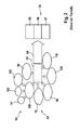
- FIG. 2 a diagram 60 in which various failure mechanisms 61 of lithium-ion batteries and their consequences 62 are highly schematic. These illustrated failure mechanisms 61 may result in a thermal runaway 64 of the battery cells 21 due to an inadmissible temperature increase 63. When a thermal runaway occurs 64, it can lead to a fire of the battery cells 66 or even bursting 67 of the battery cells 21 due to an emission of gas 65, which may occur, for example, when opening a burst valve as a result of increased battery cell internal pressure. Therefore, the occurrence of thermal runaway 64 in the use of the battery cells 21 in traction batteries most likely to be near 1 must be precluded.
- Thermal runaway 64 may occur in the event of overcharging 70 of a battery cell 21 as a result of a total discharge 80 of a battery cell 21 during the subsequent charging process or in the event of excessively high charging. and discharge currents of the battery cell 21, which may arise, for example, an external short circuit 90 occur. Further, thermal runaway 64 may also occur in the presence of a battery cell internal short circuit 100, which may arise, for example, as a result of a strong mechanical force during an accident 101 or as a result of the formation of battery cell internal dendrites 102, such as in the presence of excessive charging currents at low temperatures can arise.
- a thermal runaway 64 may also occur as a result of internal battery cell short circuits, which may be caused by contaminants of the battery cells 21, in particular by metallic foreign particles 103 present in the battery cells 21.
- a thermal runaway 64 may also occur in the event of an impermissible heating of the battery cells 110, which may arise, for example, as a result of a vehicle fire, or in the event of an overload of the battery cells 120.
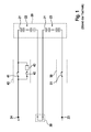
- FIG. 3 the schematic diagram of a known from the prior art battery system is shown, which includes a traction battery 20 with multiple battery cells 21 and a battery management system (BMS).
- the electronics of the battery management system has a decentralized architecture in which the monitoring and control units 130 formed from the cell monitoring electronics (CSC electronics) of the battery cells 21 are designed as satellites which are respectively provided for monitoring the functional state of one or more battery cells 21 and via internal bus system 141 with a central battery control unit (BCU) 140 communicate.
- CSC electronics cell monitoring electronics
- BCU central battery control unit
- the electronics of the battery management system in particular the monitoring electronics of the battery cells 21, is required to protect the battery cells 21 from the critical, in FIG. 2 Protected states that can lead to a thermal runaway.
- a high cost is operated, on the one hand to protect the battery cells 21 from overloading by external causes, such as by a short circuit in the inverter of an electric drive, and on the other hand to avoid that the Battery cells 21 by a malfunction of the electronics of the battery management system, such as by a faulty detection of the battery cell voltages by the monitoring and control units 130, are at risk.
- the central battery control device 140 is configured to drive the disconnect switch (relay) 41 and the charge switch (relay) 42 of the disconnecting and charging device 40.
- the activation of the disconnecting switch 41 and the charging switch 42 by means of the battery control device 140 is symbolized in the drawing by the arrow 142.
- the central battery control unit 140 is designed to control the further disconnector (relay) 51 of the separator 50. The activation of the disconnecting switch 51 by means of the battery control device 140 is symbolized by the arrow 143.
- the central battery control unit 140 is connected via a high-voltage line 144, 145 to a respective other battery terminal 24, 25. Further, the central battery control device 140 includes current sensors 150, 160 that are configured to measure a current flowing through the traction battery 20.
- the battery controller 140 also communicates with a vehicle interface via a CAN bus 146. Information about the health of the vehicle may be provided to the battery controller 140 via the CAN bus.
- the aim is therefore to increase the safety of the battery system so that no unreasonable risk occurs.
- safety tests are required for lithium ion battery cells.
- UN transport tests have to be carried out.
- the test results must be assessed according to the EUCAR Hazard Levels (EUCAR Hazard Levels).
- EUCAR Hazard Levels The battery cells 21 must comply with predetermined minimum safety levels. To achieve this, extensive additional measures are taken in the battery cells, which are intended for use in traction batteries.
- a classification according to the danger level ASIL C is expected to establish, if the safety of the battery cells 21 can not be significantly increased.
- Such additional measures are taken by integrating so-called safety devices in the battery cells. In this case, the following safety devices are typically integrated in the battery cells.
- a battery cell incorporates an Overcharge Safety Device (OSD).
- OSD Overcharge Safety Device
- Such a Kochladeconstructionsvoriques causes the battery cell during an overcharge does not exceed an EUCAR security level 4.
- the permissible range of the battery cell voltage ends at 4.2 V.
- the battery cell builds up such a high internal pressure from a battery cell voltage of about 5 V that a membrane of the overcharging safety device is arched outward and the battery cell is electrically short-circuited.
- the battery cell is discharged until a battery-internal fuse is activated.
- the short circuit of the battery cell between the two poles of the battery cell is maintained via the overcharging safety device.
- a battery cell fuse (Cell Fuse) is integrated into the battery cell.
- Cell Fuse Battery Fuse
- This fuse integrated in the battery cell is a very effective protection instrument at the battery cell level, but causes considerable problems when installing the battery cells in a series circuit of a battery module or in a battery system. There, these measures are rather counterproductive.
- a nail cell penetration safety device (Nail Penetration Safety Device (NDS)) is also integrated in a battery cell.
- NDS Near-Fielding Safety Device
- a nail penetration safety device protects the battery cell by establishing such a defined short-circuit path upon penetration of a nail or a pointed object into the battery cell, which does not lead to such strong local heating of the battery cell in the area of nail entry, which leads to a local melting of the existing separator could.
- a functional safety layer is also integrated into a battery cell.
- the functional safety layer is realized by the ceramic coating of one of the two electrodes of the battery cell, preferably by the ceramic coating of the anode.
- shock Safety Device In a battery cell also a shock safety device (Crush Safety Device) is integrated.
- the shock safety device has a similar operation as the nail penetration safety device.
- a strong mechanical deformation of the battery cell housing With a strong mechanical deformation of the battery cell housing, a defined short-circuit path is provided in the battery cell, which prevents strong local heating of the battery cell and thereby increases the safety of the battery cell.
- a battery module with a battery cell circuit having a plurality of battery cells and with a monitoring and control unit for monitoring the functional state of the battery module is provided.
- the battery module has a coupling unit with power semiconductors connected in a half-bridge arrangement for coupling the battery cell circuit to output terminals of the battery module.
- the battery module has a discharge circuit coupled to the battery cell circuit for rapid discharging of the battery module. The coupling unit and the discharge circuit can be controlled by the monitoring and control unit.
- a method for monitoring a battery module by means of a monitoring and control unit arranged in the battery module.
- the battery module is operated by means of a coupling unit comprising half-bridge arrangement switched power semiconductors for coupling the battery cell circuit of the battery mode to the output terminal of the battery module. If, during monitoring of the battery module by the monitoring and control unit, an error situation or danger situation of the battery module is detected, then the battery module by means of the coupling unit and / or by means of a coupled to the battery cell circuit of the battery module and arranged in the battery module discharge circuit, for fast discharge of the Battery mode is provided, put in a safe state.
- a battery system that has a battery with at least one battery string, in which several of the Battery modules according to the invention are arranged.
- the battery system comprises a battery management system, which is designed to communicate with the monitoring and control units of the battery modules.
- An advantage of the invention is that an intrinsically safe battery module is available, wherein the battery module can not only be operated very gently due to the controllable coupling circuit and in which an imminent damage of the battery module can be prevented by appropriate control of the coupling circuit.
- an additional safety feature is provided by providing an internal mechanism through the integrated discharging circuit for quickly discharging the battery module, with which, independently of discharge or charging currents impressed on external contacts such as the output terminals of the battery module, internal fast or ultra-fast discharging , especially in dangerous or emergency situations, can be performed.
- the coupling unit may comprise two half-bridges, each comprising a coupled to a positive pole of the battery cell circuit first power semiconductor, coupled to a negative pole of the battery circuit second power semiconductor and a center terminal and via the respective center terminal with a respective other output terminal of the battery module are connected.
- the battery module is preferably configured to operate in a normal operation, the coupling unit by means of control by the monitoring and control unit such that either a battery module voltage in positive or negative orientation or no battery cell voltage applied to the output terminals of the battery module.
- the battery module can thus be designed with a reversible output voltage. More specifically, the battery module may be modified be reversed polarity of an output voltage provided at its output terminals, so that the battery module can deliver the battery module voltage in a positive or negative orientation.
- the battery module according to the invention is particularly suitable for use in three-phase battery systems with adjustable output voltages, which are referred to as battery direct inverter, or generally in multi-phase battery systems with adjustable output voltages.
- the monitoring and control unit according to the invention is designed, in the presence of a battery cell voltage and / or battery module voltage whose amount exceeds a first voltage limit, and / or in the presence of a battery cell voltage and / or battery module voltage, the amount of which falls below a second voltage limit to put the power semiconductors of the coupling unit in a switching state in which no current flows through the battery module.
- the battery module is set in a safe state by a first power semiconductor of the half-bridge is turned on, so that a first output terminal and a second output terminal of the battery module are conductively connected, and a second power semiconductor of the same half-bridge off becomes.
- a coupling unit of two, in particular a full bridge forming, half bridges two power semiconductors connected to the first output terminal or two power semiconductors connected to the second output terminal can be switched on in each case.
- the monitoring and control unit detects an impending deep discharge starting from the battery module operating in normal operation by falling below a second limit of a battery cell voltage and / or battery module voltage, after which the battery module is transferred to a safe state in which no current flows through the battery module.
- the battery module according to the invention comprehensive battery system outward deliverable current flows only through the present in the battery module power semiconductor or semiconductor switch.
- the monitoring and control unit according to the invention is also adapted, in the presence of a charging current whose amount exceeds a predetermined or suitably selected charging current limit and / or in the presence of a (impressed outer) discharge, the amount of a predetermined or suitable selected charging current limit, to put the power semiconductor of the coupling unit in a switching state in which no current flows through the battery module.
- the monitoring and control unit detects, starting from the battery module operating in normal operation, an imminent overload due to excessively high discharge currents which, for example, can occur as a result of an external short circuit of the battery due to an error in the inverter.
- the battery module is transferred to a safe state in which no current flows through the battery module.
- the battery module is protected against loading with impermissibly high discharge currents.
- the monitoring and control unit recognizes, starting from the battery module operating in normal operation, an imminent overloading of the battery module due to excessive charging currents, the battery module then being transferred to the safe state, in which no more current flows through the battery module Battery module flows.
- the battery module is protected against loading with impermissibly high charging currents. This is particularly advantageous, for example, in the presence of very low temperatures at which the battery cells of the battery cell circuit of the battery module are particularly sensitive with respect to an educated on the anode lithium coating (lithium plating).
- the battery module via one or possibly two half-bridges, that is parallel over two half-bridges, to be discharged.
- the battery module does not release any voltage at its output terminals and, nevertheless, is nevertheless slowly discharged.
- a power semiconductor operated in particular as a controllable resistor is designed in this case including its thermal connection and cooling in accordance with the requirements.
- the monitoring and control unit is designed to detect the presence of a dangerous situation based on an evaluation of a measured cell temperature and / or battery module temperature and / or based on an evaluation of the battery cell voltages or the battery module voltage.
- a danger situation can be detected, in particular, at a cell temperature or battery module temperature exceeding a predetermined temperature limit and / or a voltage dip of the battery module voltage.
- the danger situation can also be detected by information communicated in particular by a battery management system.
- the monitoring and control unit may also be provided, in the presence of the
- Danger situation for discharging the battery module by means of at least one of the two half-bridges to power the power semiconductor of the coupling unit such that the first or the second power semiconductor of a half-bridge is turned on and the second or the first power semiconductor of the same half-bridge operates in the so-called active operation as a controllable resistance, and preferably the the first and the second power semiconductor of the other half-bridge is turned off or the first or the second power semiconductors of the two half-bridges are turned on and the second or the first power semiconductors of the two half-bridges operate in active operation.
- the discharge circuit when the danger situation is detected, the discharge circuit is activated for fast discharging of the battery module.
- the discharge circuit hereinafter also referred to as ultrafast discharge circuit (Ultra Fast Discharge Device) (UFDD) will be discharged as soon as possible.
- UFD Ultra Fast Discharge Device
- the realizable discharge currents are in particular not limited due to thermal power loss, which results, for example, in a power semiconductor operated as a controllable resistor or can be imposed on the power semiconductors in continuous operation.
- the battery module can be discharged simultaneously in a dangerous situation via the coupling unit, wherein in one in the half bridges a power semiconductor turned on and the other power semiconductor is operated in an active operation as a controllable resistor.
- the discharge circuit may comprise a series circuit with a resistor and a power semiconductor.
- the discharge circuit may in particular comprise a thyristor.
- the discharge circuit may comprise a drop-down circuit having a drain switch and a drain resistor.
- the detection of a dangerous situation due to the detection of a dangerous situation according to the invention, it is particularly advantageous to reliably detect, in particular, the performance of a test procedure during which the battery module is tested or other situations comparable to the battery module.
- the electronics of the monitoring and control unit according to the invention recognizes via the evaluation of a battery cell voltage and / or the battery module voltage that the Battery module is discharged via currents, without it being operated.
- the detection of this process can be done for example via a voltage dip of the battery module.
- the discharge of the battery module is triggered immediately via the discharge circuit according to the invention, and the battery module is then discharged substantially via the discharge circuit.
- the discharge of the battery module can be assisted via the two half-bridges.
- the battery module If the battery module is exposed to strong heating, this can be detected by the electronics of the monitoring and control unit according to the invention. As a result, the discharge of the battery module is triggered immediately, for example via the discharge circuit according to the invention and the battery module is discharged in good time via the discharge circuit.
- the electrically intrinsically safe battery module according to the invention in conjunction with the coupling unit arranged in the battery module and the monitoring and control unit, is designed so securely that, compared to a conventional battery management system, much less stringent requirements now need to be made in the battery system according to the invention.
- many previously typically performed, but not targeted measures such as equipping a battery module with an integrated
- the inventive electrically intrinsically safe battery module in conjunction with the coupling unit, the discharge circuit (ultrafast discharge circuit), and monitoring and control unit can be performed so sure that, compared to the prior art, now much lower requirements can be made to a battery management system.
- the measures implemented in the battery module for increasing the security in the presence of strong mechanical force effects can be omitted or at least much easier to implement, since the requirements on the part of the battery module are now much lower. It is possible that on the battery module and the battery cells arranged therein the battery cell circuit while strong mechanical forces, such as those simulated in UN transport tests, can safely act. This also applies in particular to a penetration of the battery cells or the battery module with pointed objects by means of a nail penetration test and / or a strong deformation of a battery cell or of the battery module by means of impacts with respect to all three spatial axes.
- the battery module can protect itself against impermissible operating states by means of the monitoring and control unit according to the invention, without having to depend on, for example, fuse functions of the electronics of a battery management system.
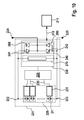
- the battery module 221 according to the first embodiment of the invention comprises a battery cell circuit 226 having a plurality of battery cells 21.
- the battery cell circuit 226 is here a series circuit, but in other embodiments of the invention may also comprise a parallel connection or a combination of a parallel connection and a series circuit.
- the battery cells are connected to a cell monitoring electronics (CSC) 228, which is provided for monitoring the individual battery cells 21.
- CSC cell monitoring electronics
- the cell monitoring electronics 228 is implemented by a central cell monitoring electronics, which is connected to all battery cells 21 and in particular can control a cell balancing.
- the battery module 221 further has a coupling unit, which is formed from a half bridge 240 with a first and a second power semiconductor 241, 242. Parallel to the power semiconductors 241, 242, a diode 260 is connected in each case, the forward direction of which extends counter to the forward direction of the corresponding power semiconductor 241, 242.
- the half-bridge 240 is connected to a first, the first power semiconductor (the first power semiconductor switch of the half-bridge from the FIG. 4 ) 241 associated with a positive pole 222 of the battery cell circuit 226 and at a second, the second power semiconductor 242 (the second power semiconductor switch of the half-bridge from the FIG. 4 ) associated with the negative terminal 223 of the battery cell circuit 226.
- the half bridge 240 is further connected at a center terminal to a first output terminal 224 of the battery module 221.
- the battery module 221 further comprises a monitoring and control unit 230 connected in parallel with the battery cell circuit 226 for monitoring the functional state of the battery cells 21 or the battery module 221.
- the monitoring and control unit 230 is equipped with an integrated drive for the power semiconductors 241, 242.
- FIG. 4 Also shown is a battery management system 211 for a battery system having a plurality of battery modules 221 according to the invention.
- the battery management system 211 is designed to communicate with the monitoring and control unit 230 or to exchange information.
- the exchange of information between the battery management system 211 and the monitoring and control unit 20 is symbolized by the double arrow 215.
- the monitoring and control unit 230 communicates with the cell monitoring electronics 228, which is configured as a central cell monitoring electronics 229 for all of the battery cells 228.
- the communication 235 can take place, for example, via a bus, in particular via a wired bus, for example a CAN bus or via FlexRay.
- the invention is not limited to a wired bus. In the following, therefore, if a (wired) bus is mentioned, in many cases the communication can also take place via wireless connections, such as Bluetooth.
- the monitoring and control electronics 230 are transmitted by the central cell monitoring electronics 229 in particular voltage and / or current measured values, which are further processed by the monitoring and control unit 230 for security monitoring, as shown below.
- the first power semiconductor 241 of the half-bridge 240 is turned off and the second Power semiconductor 242 is turned on. Since the battery module voltage is within the range U min_modul and U max_modul , the diode 260 of the first power semiconductor 241 blocks even in imminent overcharge, for example in a malfunction when charging the battery or the battery module 221. This can safely prevent further charging of the battery module 221 become.
- the first power semiconductor 241 of the half-bridge 240 is turned off and the second power semiconductor 242 is turned on. There then flows no more current through the battery module 221.
- the first power semiconductor 241 of the half-bridge 240 is turned off and the second power semiconductor 242 is turned on. Then, no current flows through the battery module 221. The battery module 221 is thus protected against a load with excessively high discharge currents.
- the monitoring and control unit 230 Recognizes the monitoring and control unit 230, starting from the normal operation of the battery module 221 impending overload of the battery module 221 by excessive charging currents, for example, at very low temperatures in which the battery cells 21 of the battery cell circuit 226 is particularly sensitive to an educated especially on the anode lithium coating,
- the monitoring and control unit 230 By means of the monitoring and control unit 230, the first power semiconductor 241 of the half-bridge 240 turned off and the second power semiconductor 242 is turned on. Then, no current flows through the battery module 221.
- the battery module 221 is thus protected from loading with impermissibly high charging currents.
- the battery module 221 can be discharged via the half bridge 240.
- the second power semiconductor 242 is turned on and the first power semiconductor 241 is operated in so-called active operation as a controllable resistor.
- the battery module 221 then outputs no voltage at its output terminals 224, 225 and is nevertheless slowly discharged.
- the realizable discharge currents are limited by the thermal power loss that can be imposed on the power semiconductor 241 operated as a controllable resistor in continuous operation.
- a power semiconductor 241 operated in particular as a controllable resistor, including its thermal connection and cooling, will therefore be designed in accordance with the requirements.
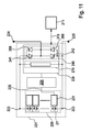
- the battery module 221 according to the first embodiment of the invention further includes a discharge circuit 270 as an Ultra Fast Discharge Device (UFDD).
- the discharge circuit 270 is provided in the battery module 221 for discharging the battery cells 21 by means of a discharge current flowing through the discharge circuit 270. If the monitoring and control unit 230 of the intrinsically safe battery module 221 according to the invention is informed by a battery management system 211 which is arranged in a battery system having a plurality of such battery modules 221 that the vehicle in which the battery system according to the invention has been installed has had an accident, the battery module becomes 221 discharged via the discharge circuit 270 quickly. In order to support the discharge circuit 270, the battery module 221 can also be discharged via the half-bridge 240 at the same time.
- UDD Ultra Fast Discharge Device
- the second power semiconductor 242 of the half-bridge 240 is thus switched on by means of the monitoring and control unit 230.
- the battery module 221 then outputs at its terminals or output terminals 224, 225 no voltage during discharge.
- the discharge circuit 270 may be configured so that the battery module 221 can be discharged with very large discharge currents near the short circuit. The battery module 221 is thus brought into a safe state very quickly. In this way, situations can be mastered at the vehicle level where the battery module 221 is mechanically severely deformed or penetrated by sharp objects.
- the first power semiconductor 241 can also be operated in active operation as a controllable resistor by means of the monitoring and control unit 230.
- the battery module 221 according to the invention is shown according to a second embodiment of the invention.
- the discharge circuit (UFDD) 270 shown in more detail and here comprises a connected between the positive terminal 222 and the negative terminal 223 of the battery cell circuit 226 series circuit of a power semiconductor 271 and a resistor 272nd
- the invention is not limited to a particular embodiment of the (ultrafast) discharge circuit 270. So be in the FIGS. 6 and 7 Further exemplary embodiments of the ultrafast discharge circuit (UFDD) 270 are shown.
- the discharge circuit 270 is one of the essential functional units in order to obtain an intrinsically safe battery module 221, and with which the battery module 221 is to be quickly brought to a safe state by discharging.
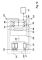
- FIG. 6 an implementation of the discharge circuit 270 is shown, which is based on the use of a (short circuit) thyristor 273. Thyristors are characterized by exceptional robustness and current carrying capacity and are therefore suitable for the present application, semiconductor devices.
- the local realization of the ultrafast discharge circuit 270 comprises a series connection of an ohmic resistor 272 and a Kurz gleichthyristors 273.
- the ohmic resistance 272 can either via the line resistances and the Contact resistors 274, 275 of the short circuit or be realized via a dedicated component.
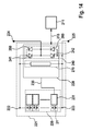
- FIG. 7 Another embodiment of the ultrafast discharge circuit 270 is shown, which is based on a Abtakt or a Abtaktscnies.
- the Abtakter can be constructed on the basis of an on and off electronic semiconductor valve 276 and a Abtaktwiderstand 272, wherein the semiconductor valve 276 has been controlled by the monitoring and control unit 230 according to the invention.
- the ohmic resistance of the Abtaktwiderstandes 272 limited together with the internal resistance of the battery module 221 and the battery cells 21, the maximum discharge during the rapid discharge of the battery module 221.
- For the on and off switchable electronic semiconductor switch 276 are particularly MOSFETs, as these due to the low requirements of the reverse voltage can be realized with very low on-resistance.
- An energy extraction from the battery module 221 can be controlled via the Abtaktscnies.
- energy can quickly be taken from the battery module 221 at the beginning of the discharge with a continuously switched on Abtakter.
- the drain resistor 272 and the Abtaktschalters 276 can then be changed to a pulsed operation or in a block operation.
- Inverse diodes 277, 278, which are connected in parallel, are shown.
- the inventive ultrafast discharge circuit 270 can thus be used for the realization of an intrinsically safe battery module 221.
- the battery module 221 can be protected against overcharging, over-discharging and overloading by excessively high charging and discharging currents.
- the limits for the electrical safety can be adjusted dynamically, for example as a function of the temperature of the battery cell 21.
- the battery module 221 is also intrinsically safe even with strong mechanical forces, as they can occur, for example, in an accident.
- the battery module 221 is discharged as quickly as possible upon detection of a critical condition via the discharge circuit 270.
- the battery module 221 is thus intrinsically safe in the event of severe heating.
- the battery module 221 is discharged as quickly as possible upon detection of a critical condition via the discharge circuit 270.
- the design of the discharge circuit 270 may be such that the discharge current does not exceed a maximum permissible maximum short-circuit current for the battery module 221.
- the resulting short-circuit current path depends on the specific conditions. Therefore, the behavior of a battery module can not be accurately predicted and is not reproducible. This disadvantage can be avoided with the discharge circuit presented here.
- the voltage of the battery module 221 via the half-bridge 240 can be specified exactly. If the second power semiconductor 242 of the half-bridge 240 is also automatically switched on when the discharge circuit 270 is activated, the intrinsically safe battery module 221 has the voltage 0V at its output terminals 224, 225, while the rapid discharge takes place via the discharge circuit 270.
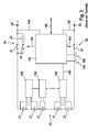
- FIG. 8 the schematic diagram of a battery module 221 is shown according to a further embodiment of the invention.
- the battery module 221 here has two half bridges 240, 250. More specifically, the battery module 221 includes FIG. 8 a battery cell circuit 226 and a coupling unit consisting of a first half bridge (the right half bridge from the FIG. 9 ) 240 with a first and a second power semiconductor 241, 242 and a second half-bridge (the left half-bridge from the FIG. 9 ) 250 with a first and a second power semiconductor 251, 252 is formed.
- the two half bridges 240, 250 together form a full bridge with four power semiconductors 241, 242, 251, 252. Parallel to the power semiconductors 241, 242, 251, 252, a diode 260 is connected in each case whose forward direction is opposite to the forward direction of the corresponding power semiconductor 241, 242 , 251, 252 runs.
- the first half-bridge 240 is connected to a first, the first power semiconductor (the first power semiconductor switch of the right half-bridge from the FIG. 9 ) 241 associated with a positive pole 222 of the battery cell circuit 226 and at a second, the second power semiconductor 242 (the second Power semiconductor switch of the right half-bridge from the FIG. 9 ) associated with the negative terminal 223 of the battery cell circuit 226.
- the first half-bridge 240 is further connected at a middle terminal to a first output terminal 224 of the battery module 221.
- the second half-bridge 250 is connected to a first, the first power semiconductor (the first power semiconductor switch of the left half-bridge from the FIG. 9 ) Associated with the positive terminal 222 of the battery cell circuit 226 and at a second, the second power semiconductor (the second power semiconductor switch of the left half bridge from the FIG. 9 ) 252 associated with the negative terminal 223 of the battery cell circuit 226.
- the second half-bridge 250 is further connected at a center terminal to a second output terminal 225 of the battery module 221.
- the safety features of the full bridge after FIG. 8 are similar to that of the half bridge after FIG. 4 , Due to the full-bridge arrangement, however, the power semiconductors 241, 242, 251, 252 can be controlled by means of the monitoring and control unit 230 according to the invention such that, during normal operation of the battery module 221, the battery module voltage is delivered to the output terminals 224, 225 in the positive orientation (+ U battery module ) should, the first power semiconductor 241 of the first half-bridge 240 and the second power semiconductor 252 of the second half-bridge 250 is turned on and the other two power semiconductors 242, 251 are turned off.
- the power semiconductors 241, 242, 251, 252 can be controlled by means of the monitoring and control unit 230 according to the invention such that, in normal operation, the battery module 226 is to deliver the battery module voltage to the output terminals 224, 225 in a negative orientation (-U battery module) second power semiconductors 242 of the first half-bridge 240 and the first power semiconductor 251 of the second half-bridge 250 turned on and the other two power semiconductors 241, 252 are turned off.
- the battery module 226 is to deliver the battery module voltage to the output terminals 224, 225 in a negative orientation (-U battery module) second power semiconductors 242 of the first half-bridge 240 and the first power semiconductor 251 of the second half-bridge 250 turned on and the other two power semiconductors 241, 252 are turned off.
- the power semiconductors 241, 242, 251, 252 can also be controlled by means of the monitoring and control unit 230 according to the invention such that during normal operation of the battery module 221 optionally also a functional state of the battery module 221 is adjustable, in which the battery module 221 emits no output voltage. In this state, either the first power semiconductors 241, 251 of the two half bridges 240, 250 are switched on and the other two power semiconductors 242, 252 are switched off or the second power semiconductors 242, 252 of the two half bridges 240, 250 are switched on and the other two power semiconductors 241, 251 are switched off ,
- the battery module 221 can be connected via one of the two half bridges 240, 250 or can be discharged in parallel via both half-bridges 240, 250, but the ultra-fast discharge circuit 270 is preferably used for charging.
- the monitoring and control unit 230 recognizes the evaluation of a battery cell voltage and / or the battery module voltage that the battery module 221 is discharged by currents without being operated. This can be done for example by detecting a voltage dip of the battery module 221.
- the monitoring and control unit 230 then immediately triggers the discharging of the battery module 221 via the discharge circuit 270 according to the invention, and the battery module 221 is then discharged substantially via the discharge circuit 270.
- the battery module 221 If the battery module 221 is exposed to strong heating, this can be detected by the monitoring and control unit 230. Since the time constants for the heating of the battery module 221 or the battery cells 21 are generally very high, a discharge of the battery module 221 can be effected in good time via the discharge circuit 270 according to the invention before a battery cell temperature and / or a battery module temperature exceed critical values. Optionally, a discharge of the battery module 221 can also take place via the two half bridges 240, 250. In order to support the discharge circuit 270, in particular the two second power semiconductors 242, 252 of the two half bridges 240, 250 are switched on by means of the monitoring and control unit 230. As a result, the battery module 221 becomes much more secure than in the prior art.
- the technology is a significant improvement, because otherwise very high negative voltages, which can be up to -400 V in electric vehicle batteries, for example, when activating a battery cell-internal fuse, which cause the electronics of a battery management system big problems.
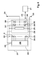
- FIG. 9 the schematic diagram of a battery module 221 is shown according to another embodiment of the invention.
- the battery cells 21 are here each equipped with its own cell monitoring electronics 231.
- central cell monitoring electronics 229 are also present, although some functions of cell monitoring instead of in the central cell monitoring electronics 229 are now carried out in the individual battery cells 21 or in the corresponding battery cell cell monitoring electronics 231.
- the central cell monitoring electronics 229 communicates with the individual cell monitoring electronics 231 in the battery cells.
- This communication 235 can take place by means of a bus, to which both the central cell monitoring electronics 229 and the battery cell-specific cell monitoring electronics 231 are connected.
- the monitoring and control unit 230 according to the invention communicates in a manner similar to that according to FIGS FIGS. 4 . 5 , and 8th , with the central cell monitoring electronics 229.
- FIG. 10 the schematic diagram of a battery module according to yet another embodiment of the invention is shown.
- the battery cell-specific cell monitoring electronics 231 are connected in each case via their own, that is to say separate communication bus with the central cell monitoring electronics 229, which on the output side has a correspondingly higher number of interfaces for this purpose.
- FIG. 11 shows the block diagram of a battery module 221 according to yet another embodiment of the invention, wherein according to this
- a communication link 235 between a battery cell-own cell monitoring electronics 231 and the central cell monitoring electronics 229 is present, so that the central cell monitoring electronics 229 communicates with only one of the cell monitoring electronics 231 directly.
- the battery cell-specific cell monitoring electronics 231 communicate with each other, for example via a daisy-chain, so that all relevant battery cell data is transmitted first via the daisy-chain and then via the communication link, which is designated in the figures by reference numeral 235.
- the invention is not limited to such battery cell own cell monitoring electronics 231, which are arranged within a respective battery cell 21.
- a corresponding separate cell monitoring electronics 231 is arranged outside the battery cell 21 and connected to the battery cell 21, wherein optionally a central (main) cell monitoring electronics 229 may be present.
- FIGS. 12 to 14 show further embodiments of the invention, wherein in these embodiments, the monitoring and control unit 230 is directly connected to the battery cell-specific cell monitoring electronics 231, without the need for central cell monitoring electronics 229 is present. Thus, some cell monitoring tasks are performed directly in / on the battery cells 21, with determined measurement results and outputs of the cell monitoring electronics 231 being communicated directly to the monitoring and driving unit 230.
- the communication 235 between the monitoring and control unit 230 and the cell monitoring electronics 231 is similar to the embodiments described above in connection with the FIGS. 9 to 11 with the difference that the one or more communication buses are connected to the monitoring and driving unit 230 and not to a central cell monitoring unit.
- FIG. 12 an embodiment of the invention, in which the monitoring and control unit 230 via a bus with the cell monitoring electronics 231 is connected, and in FIG. 13 There are several communication links or buses between the monitoring and control unit 230 on the one hand and the respective cell monitoring electronics 231 on the other hand available.
- FIG. 14 an embodiment in which the cell monitoring electronics 231 communicate with each other, wherein one of the cell monitoring electronics 231 is connected to the monitoring and control unit 230.
- central cell monitoring electronics 229 and battery cell cell monitoring electronics 231 may be arranged in a battery module 221 having a monitoring and driving unit 230 with the unloading device 270 of the present invention. Examples of this were given above in connection with the FIGS. 8 to 14 discussed. So are those in the FIGS. 4 and 5 shown battery modules 221 is not limited to the illustrated there exemplary topology. Rather, the topology of the in the FIGS. 4 to 5 shown battery modules 221 analog also as in the FIGS. 9 to 14 be constructed circuit topologies constructed. In other words, although according to the FIGS. 4 and 5 the interconnection topology for the communication 235 between the monitoring and control unit 230 and the cell monitoring electronics 228, 229 of the in FIG. 8 in other embodiments, the interconnection topology may also be in the FIGS. 9 to 14 shown topologies, these alternative embodiments are not shown separately for the sake of brevity at this point.
- the battery modules 221 according to the invention presented here are not limited to lithium-ion battery cells. Rather, they may include other battery cell technologies, such as nickel-metal hybrid battery cells.
- the overcharge safety devices (OSDs) and the overcharging safety devices previously used can be used Battery cell fuses are eliminated.
- the measures used to increase the security of mechanical deformation or penetration, such as the establishment of a battery module with an integrated needle penetration safety device can either also be omitted or at least made much easier.
- ASIL classification QM quality assurance measures
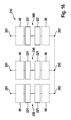
- FIG. 15 shows the structure of a battery with an exemplary embodiment of the battery module 221 according to the invention.
- each battery module 221 of the battery shown there has a discharge circuit 270 and a coupling unit with a half-bridge 240.
- the explicit representation of the monitoring and control unit 230 arranged in each battery module 221 has been dispensed with.
- the battery modules 221 according to the invention are particularly suitable for use in battery direct inverters 210 with output voltages which can be set in stages.
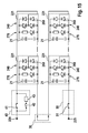
- FIG. 16 An example of the use of the electrically intrinsically safe battery modules 221 according to the invention presented here is that in FIG. 16 illustrated battery direct inverter 210.
- the in the FIG. 16 shown battery direct inverter 210 is a three-phase battery system with a step-adjustable output voltage.
- the battery direct inverter 210 comprises three battery strings 280, 290, 300, each of which has a series connection of a plurality of battery modules 221 according to the invention. These series connections of the battery strings 280, 290, 300 are connected to the positive battery branch poles 281, 291, 301 are each connected via a charging and disconnecting device 40 and with the negative battery bank poles 282, 292, 302 each via a separator 50.
- the battery cells or battery modules are controlled such that their operating parameters are within the respective limits which are necessary for safe operation.
- lithium ion battery cells are typically operated within a voltage range of Umin to Umax of 2.8V to 4.2V, or preferably 3.0V to 4.2V volts. This applies in particular to safety-relevant values Umin_safety or Umax_safety. However, these specifications apply to the voltages to be measured U battery cell at idle, that is, when no current flows through the battery cell. It is important to observe these limits, otherwise the electrodes may be damaged.
- the open circuit voltage of the battery cells depends essentially on their state of charge. In this case, typically a charge state SOC of 0%, at 3.5 V a charge state of 20%, and at 4.2 V a state of charge of 100% is assumed for a voltage U battery cell of 2.8 V, these values being in each case of type and Material of the cathode, the anode, and / or the electrolyte used.
- the battery cell voltages UBatteriezelle may differ from the above figures.
- the open circuit voltage is 3.5 V and the internal resistance of the battery cell at 25 ° C is 10 m ⁇ .
- the internal resistance of the battery cell can be as high as 50 m ⁇ , for example, at a temperature of 0 ° C
- the Umax value may be between 4.2V and 5.0V and the value of Umin is between 1.5V and 4.2V, preferably between 1.8V and 4.15V, but these values do not refer to the open circuit voltage.
- the allowable module open circuit voltage UBatteriemodul is between n x 2.8 V to n x 4.2 V, where n is the number of battery cells connected in series.
- Tmax-safety 46 ° C to 80 ° C, preferably 50 ° C to 60 ° C should not be exceeded.
- Tau B at which the battery cells are operated, should not exceed 40 ° C.
- the battery currents through the battery cells should not be outside a range of -1000 A to +1000 A, preferably -600 A to +600 A, more preferably -500 A to +500 A, even more preferably -450 A to +450 A, and more preferably -350 A to + 350 A, are.
- the internal pressure of a battery cell should not leave the pressure range of 2 bar to 8 bar, preferably 3 bar to 7 bar.
Landscapes
- Engineering & Computer Science (AREA)
- Power Engineering (AREA)
- Life Sciences & Earth Sciences (AREA)
- Sustainable Development (AREA)
- Sustainable Energy (AREA)
- Transportation (AREA)
- Mechanical Engineering (AREA)
- Secondary Cells (AREA)
- Charge And Discharge Circuits For Batteries Or The Like (AREA)
Applications Claiming Priority (1)
| Application Number | Priority Date | Filing Date | Title |
|---|---|---|---|
| DE102013204510.7A DE102013204510A1 (de) | 2013-03-15 | 2013-03-15 | Elektrisch eigensicheres Batteriemodul mit ultraschneller Entladeschaltung und Verfahren zur Überwachung eines Batteriemoduls |
Publications (2)
| Publication Number | Publication Date |
|---|---|
| EP2777979A2 true EP2777979A2 (fr) | 2014-09-17 |
| EP2777979A3 EP2777979A3 (fr) | 2014-12-24 |
Family
ID=50070465
Family Applications (1)
| Application Number | Title | Priority Date | Filing Date |
|---|---|---|---|
| EP14154650.7A Withdrawn EP2777979A3 (fr) | 2013-03-15 | 2014-02-11 | Module de batterie électrique à sécurité intrinsèque avec circuit de décharge ultra-rapide et procédé de surveillance d'un module de batterie |
Country Status (3)
| Country | Link |
|---|---|
| EP (1) | EP2777979A3 (fr) |
| CN (1) | CN104052102B (fr) |
| DE (1) | DE102013204510A1 (fr) |
Cited By (7)
| Publication number | Priority date | Publication date | Assignee | Title |
|---|---|---|---|---|
| CN106199457A (zh) * | 2016-09-29 | 2016-12-07 | 福州福光电子有限公司 | 蓄电池组中开路电池的在线快速检测装置和方法 |
| EP3142165A1 (fr) * | 2015-09-10 | 2017-03-15 | Lithium Energy and Power GmbH & Co. KG | Systeme de batterie dote d'une protection de decharge complete et/ou de surcharge |
| EP3358648A1 (fr) | 2017-02-03 | 2018-08-08 | Lithium Energy and Power GmbH & Co. KG | Dispositif de déchargement d'une pile de batterie et une pile de batterie |
| EP3376554A1 (fr) | 2017-03-17 | 2018-09-19 | Lithium Energy and Power GmbH & Co. KG | Unité de décharge et/ou d'arrêt rapide, cellule de batterie, module de cellule ou batterie et appareil |
| DE102017220364A1 (de) | 2017-11-15 | 2019-05-16 | Robert Bosch Gmbh | Elektrisches Überbrückungselement, elektrisches Energiespeichermodul, elektrischer Energiespeicher und Vorrichtung |
| EP3772793A1 (fr) * | 2019-08-07 | 2021-02-10 | Beijing Xiaomi Mobile Software Co., Ltd. | Module de batterie, procédé et appareil de charge, dispositif électronique et support d'informations lisible |
| EP3227133B1 (fr) * | 2014-12-04 | 2021-07-07 | Rayner, Dignan Herbert | Appareil et système pour fournir une source d'énergie secondaire pour un véhicule électrique |
Families Citing this family (9)
| Publication number | Priority date | Publication date | Assignee | Title |
|---|---|---|---|---|
| KR102335296B1 (ko) * | 2014-11-28 | 2021-12-06 | 로베르트 보쉬 게엠베하 | 무선 네트워크 기반 배터리 관리 시스템 |
| EP3166172B1 (fr) * | 2015-11-05 | 2019-01-09 | Lithium Energy and Power GmbH & Co. KG | Élement de batterie comprenant une unite de decharge rapide et procede de decharge rapide pour un tel element de batterie |
| EP3336624B1 (fr) * | 2016-12-19 | 2019-02-06 | Siemens Aktiengesellschaft | Système comprenant deux modules redondants se surveillant mutuellement |
| DE102017211999A1 (de) | 2017-07-13 | 2019-01-17 | Robert Bosch Gmbh | Steueranordnung, Zellenanordnung und Arbeitsvorrichtung |
| DE102017211989A1 (de) | 2017-07-13 | 2019-01-17 | Robert Bosch Gmbh | Steueranordnung, Zellenanordnung und Arbeitsvorrichtung |
| DE102018200173A1 (de) * | 2018-01-08 | 2019-07-11 | Robert Bosch Gmbh | Batteriesystem für ein Elektrofahrzeug, Verfahren zum Betrieb eines Batteriesystems und Elektrofahrzeug |
| DE102018201677A1 (de) * | 2018-02-05 | 2019-08-08 | Gs Yuasa International Ltd. | Batteriesystem für ein Elektrofahrzeug, Verfahren zum Betrieb eines Batteriesystems und Elektrofahrzeug |
| DE102018201690A1 (de) * | 2018-02-05 | 2019-08-08 | Robert Bosch Gmbh | Batteriesystem für ein Elektrofahrzeug, Verfahren zum Betrieb eines Batteriesystems und Elektrofahrzeug |
| DE102019214168A1 (de) * | 2019-09-18 | 2021-03-18 | Robert Bosch Gmbh | Verfahren zum Betrieb eines Batteriemoduls und Batteriemodul |
Citations (2)
| Publication number | Priority date | Publication date | Assignee | Title |
|---|---|---|---|---|
| US20050077874A1 (en) * | 2001-12-06 | 2005-04-14 | Panasonic Ev Energy Co., Ltd. | Battery power source apparatus of electric car |
| DE102011006512A1 (de) * | 2011-03-31 | 2012-10-04 | Robert Bosch Gmbh | Steuereinheit |
Family Cites Families (9)
| Publication number | Priority date | Publication date | Assignee | Title |
|---|---|---|---|---|
| KR20070047384A (ko) * | 2005-11-02 | 2007-05-07 | 현대자동차주식회사 | 하이브리드 자동차용 전기동력시스템 및 하이브리드자동차용 전기동력시스템의 고장 진단 방법 |
| KR100906249B1 (ko) * | 2006-09-11 | 2009-07-07 | 주식회사 엘지화학 | 안전성 향상을 위한 전지 시스템의 제어방법 |
| DE102009028974A1 (de) * | 2009-08-28 | 2011-03-03 | Robert Bosch Gmbh | Halbbrücken-Konverter für ein Batteriesystem und Batteriesystem |
| EP2355229A1 (fr) * | 2010-02-08 | 2011-08-10 | Fortu Intellectual Property AG | Système de batterie à courant élevé et procédé de commande d'un système de batterie à courant élevé |
| DE102010027864A1 (de) * | 2010-04-16 | 2011-12-15 | Sb Limotive Company Ltd. | Batterie mit variabler Ausgangsspannung |
| DE102010027857A1 (de) * | 2010-04-16 | 2011-10-20 | Sb Limotive Company Ltd. | Koppeleinheit und Batteriemodul mit integriertem Pulswechselrichter und erhöhter Zuverlässigkeit |
| DE102010041014A1 (de) * | 2010-09-20 | 2012-03-22 | Sb Limotive Company Ltd. | Batteriesystem mit variabel einstellbarer Zwischenkreisspannung |
| DE102010064325A1 (de) * | 2010-12-29 | 2012-07-05 | Robert Bosch Gmbh | System mit einer elektrischen Maschine |
| DE102011079365A1 (de) * | 2011-07-19 | 2013-01-24 | Sb Limotive Company Ltd. | Verfahren zum Laden einer Batterie und Batterie zur Ausführung des Verfahrens |
-
2013
- 2013-03-15 DE DE102013204510.7A patent/DE102013204510A1/de not_active Withdrawn
-
2014
- 2014-02-11 EP EP14154650.7A patent/EP2777979A3/fr not_active Withdrawn
- 2014-03-14 CN CN201410096592.1A patent/CN104052102B/zh not_active Expired - Fee Related
Patent Citations (3)
| Publication number | Priority date | Publication date | Assignee | Title |
|---|---|---|---|---|
| US20050077874A1 (en) * | 2001-12-06 | 2005-04-14 | Panasonic Ev Energy Co., Ltd. | Battery power source apparatus of electric car |
| DE102011006512A1 (de) * | 2011-03-31 | 2012-10-04 | Robert Bosch Gmbh | Steuereinheit |
| WO2012130498A2 (fr) * | 2011-03-31 | 2012-10-04 | Robert Bosch Gmbh | Unité de commande |
Cited By (10)
| Publication number | Priority date | Publication date | Assignee | Title |
|---|---|---|---|---|
| EP3227133B1 (fr) * | 2014-12-04 | 2021-07-07 | Rayner, Dignan Herbert | Appareil et système pour fournir une source d'énergie secondaire pour un véhicule électrique |
| EP3142165A1 (fr) * | 2015-09-10 | 2017-03-15 | Lithium Energy and Power GmbH & Co. KG | Systeme de batterie dote d'une protection de decharge complete et/ou de surcharge |
| CN106199457A (zh) * | 2016-09-29 | 2016-12-07 | 福州福光电子有限公司 | 蓄电池组中开路电池的在线快速检测装置和方法 |
| EP3358648A1 (fr) | 2017-02-03 | 2018-08-08 | Lithium Energy and Power GmbH & Co. KG | Dispositif de déchargement d'une pile de batterie et une pile de batterie |
| WO2018141444A1 (fr) | 2017-02-03 | 2018-08-09 | Lithium Energy and Power GmbH & Co. KG | Dispositif de décharge d'un élément de batterie et élément de batterie |
| EP3376554A1 (fr) | 2017-03-17 | 2018-09-19 | Lithium Energy and Power GmbH & Co. KG | Unité de décharge et/ou d'arrêt rapide, cellule de batterie, module de cellule ou batterie et appareil |
| WO2018166706A1 (fr) | 2017-03-17 | 2018-09-20 | Lithium Energy and Power GmbH & Co. KG | Unité de décharge et/ou d'arrêt rapide, cellule de batterie, module de cellule ou batterie, et appareil |
| DE102017220364A1 (de) | 2017-11-15 | 2019-05-16 | Robert Bosch Gmbh | Elektrisches Überbrückungselement, elektrisches Energiespeichermodul, elektrischer Energiespeicher und Vorrichtung |
| EP3772793A1 (fr) * | 2019-08-07 | 2021-02-10 | Beijing Xiaomi Mobile Software Co., Ltd. | Module de batterie, procédé et appareil de charge, dispositif électronique et support d'informations lisible |
| US11398650B2 (en) | 2019-08-07 | 2022-07-26 | Beijing Xiaomi Mobile Software Co., Ltd. | Battery module, charging method and apparatus, electronic device, and readable storage medium |
Also Published As
| Publication number | Publication date |
|---|---|
| CN104052102B (zh) | 2017-11-21 |
| DE102013204510A1 (de) | 2014-09-18 |
| CN104052102A (zh) | 2014-09-17 |
| EP2777979A3 (fr) | 2014-12-24 |
Similar Documents
| Publication | Publication Date | Title |
|---|---|---|
| EP2777979A2 (fr) | Module de batterie électrique à sécurité intrinsèque avec circuit de décharge ultra-rapide et procédé de surveillance d'un module de batterie | |
| DE102013204541A1 (de) | Batteriezelleinheit mit Batteriezelle und ultraschneller Entladeschaltung und Verfahren zur Überwachung einer Batteriezelle | |
| DE102013204526A1 (de) | Batteriezelleinheit mit einer Batteriezelle und einer Überwachungs- und Ansteuerungseinheit zur Überwachung der Batteriezelle und Verfahren zur Überwachung einer Batteriezelle | |
| DE102013218077B4 (de) | Batteriezelleinrichtung und Verfahren zur Bestimmung einer komplexen Impedanz einer in einer Batteriezelleinrichtung angeordneten Batteriezelle | |
| DE102013204534A1 (de) | Batteriezelleinrichtung mit Kurzschlusssicherheitsfunktion und Verfahren zum Überwachen einer Batteriezelle | |
| DE102013204532A1 (de) | Batteriezelleinrichtung mit Überhitzungssicherheitsfunktion und Verfahren zum Überwachen einer Batteriezelle | |
| EP3669432A1 (fr) | Dispositif d'interruption pour un réseau d'alimentation électrique | |
| DE102013218081A1 (de) | Batteriemoduleinrichtung und Verfahren zur Bestimmung einer komplexen Impedanz eines in einer Batteriemoduleinrichtung angeordneten Batteriemoduls | |
| DE102013204527A1 (de) | Batteriezelleinrichtung mit Lithiumablagerungssicherheitsfunktion und Verfahren zum Überwachen einer Batteriezelle | |
| DE102021201468B3 (de) | Architektur und Schaltungstopologie zur Sicherstellung einer schaltbaren allpoligen galvanischen Trennung in Hochvoltbatteriesystemen | |
| DE102019202164A1 (de) | Schutzvorrichtung, Batterie, Kraftfahrzeug und Verfahren zum Abschalten einer Batteriezelle | |
| DE102014200262B4 (de) | Batteriesystem mit einer Batterie, die mit mindestens einem ihrer Hochvoltanschlüssen über ein Schütz verbindbar ist, und Verfahren zum Schalten eines solchen Schützes | |
| DE102013204539A1 (de) | Batteriezelleinrichtung mit Feinschlusssicherheitsfunktion und Verfahren zum Überwachen einer Batteriezelle | |
| DE102016107706B4 (de) | Ansteuerungsvorrichtung für eine pyrotechnische Sicherungsvorrichtung | |
| EP2779354B1 (fr) | Module de batterie électrique à sécurité intrinsèque avec tension de sortie à polarité inversable et procédé de surveillance d'un module de batterie | |
| WO2014191135A1 (fr) | Séparation de modules dans des systèmes de batterie en cas d'accidents | |
| DE102012213926A1 (de) | Batteriemodul, Batteriemanagementsystem, System zur Versorgung eines Antriebs einer zur Drehmomenterzeugung geeigneten Maschine mit elektrischer Energie und Kraftfahrzeug | |
| DE102013204538A1 (de) | Batteriezellmodul und Verfahren zum Betreiben eines Batteriezellmoduls | |
| DE102017107889A1 (de) | Sicherheitsüberwachungseinheit | |
| WO2015173000A1 (fr) | Procédé d'exploitation d'un ensemble accumulateur d'énergie, système de gestion de batterie pour la mise en œuvre d'un tel procédé, et ensemble accumulateur d'énergie doté d'un tel système de gestion de batterie | |
| DE102013204509A1 (de) | Batteriemodul und Verfahren zum Überwachen eines Batteriemoduls | |
| DE102009058884A1 (de) | Schaltvorrichtung zum Schutz einer Batterie | |
| DE102013204524A1 (de) | Batteriezelleinrichtung mit Überladungssicherheitsfunktion und Verfahren zum Überwachen einer Batteriezelle | |
| DE102013204529A1 (de) | Batteriezelleinrichtung mit Überdrucksicherheitsfunktion und Verfahren zum Überwachen einer Batteriezelle | |
| DE102013204537A1 (de) | Batteriezelleinrichtung mit Unfallsicherheitsfunktion und Verfahren zum Überwachen einer Batteriezelle |
Legal Events
| Date | Code | Title | Description |
|---|---|---|---|
| PUAI | Public reference made under article 153(3) epc to a published international application that has entered the european phase |
Free format text: ORIGINAL CODE: 0009012 |
|
| 17P | Request for examination filed |
Effective date: 20140211 |
|
| AK | Designated contracting states |
Kind code of ref document: A2 Designated state(s): AL AT BE BG CH CY CZ DE DK EE ES FI FR GB GR HR HU IE IS IT LI LT LU LV MC MK MT NL NO PL PT RO RS SE SI SK SM TR |
|
| AX | Request for extension of the european patent |
Extension state: BA ME |
|
| PUAL | Search report despatched |
Free format text: ORIGINAL CODE: 0009013 |
|
| AK | Designated contracting states |
Kind code of ref document: A3 Designated state(s): AL AT BE BG CH CY CZ DE DK EE ES FI FR GB GR HR HU IE IS IT LI LT LU LV MC MK MT NL NO PL PT RO RS SE SI SK SM TR |
|
| AX | Request for extension of the european patent |
Extension state: BA ME |
|
| RIC1 | Information provided on ipc code assigned before grant |
Ipc: B60L 11/18 20060101AFI20141114BHEP Ipc: B60L 3/00 20060101ALI20141114BHEP |
|
| R17P | Request for examination filed (corrected) |
Effective date: 20150624 |
|
| RBV | Designated contracting states (corrected) |
Designated state(s): AL AT BE BG CH CY CZ DE DK EE ES FI FR GB GR HR HU IE IS IT LI LT LU LV MC MK MT NL NO PL PT RO RS SE SI SK SM TR |
|
| 17Q | First examination report despatched |
Effective date: 20160707 |
|
| STAA | Information on the status of an ep patent application or granted ep patent |
Free format text: STATUS: THE APPLICATION IS DEEMED TO BE WITHDRAWN |
|
| 18D | Application deemed to be withdrawn |
Effective date: 20170902 |