EP2778035A1 - Système de poignée de bicyclette - Google Patents
Système de poignée de bicyclette Download PDFInfo
- Publication number
- EP2778035A1 EP2778035A1 EP14159251.9A EP14159251A EP2778035A1 EP 2778035 A1 EP2778035 A1 EP 2778035A1 EP 14159251 A EP14159251 A EP 14159251A EP 2778035 A1 EP2778035 A1 EP 2778035A1
- Authority
- EP
- European Patent Office
- Prior art keywords
- switching
- bicycle handle
- handle system
- housing
- membrane
- Prior art date
- Legal status (The legal status is an assumption and is not a legal conclusion. Google has not performed a legal analysis and makes no representation as to the accuracy of the status listed.)
- Withdrawn
Links
Images
Classifications
-
- H—ELECTRICITY
- H01—ELECTRIC ELEMENTS
- H01H—ELECTRIC SWITCHES; RELAYS; SELECTORS; EMERGENCY PROTECTIVE DEVICES
- H01H3/00—Mechanisms for operating contacts
-
- B—PERFORMING OPERATIONS; TRANSPORTING
- B62—LAND VEHICLES FOR TRAVELLING OTHERWISE THAN ON RAILS
- B62M—RIDER PROPULSION OF WHEELED VEHICLES OR SLEDGES; POWERED PROPULSION OF SLEDGES OR SINGLE-TRACK CYCLES; TRANSMISSIONS SPECIALLY ADAPTED FOR SUCH VEHICLES
- B62M6/00—Rider propulsion of wheeled vehicles with additional source of power, e.g. combustion engine or electric motor
- B62M6/40—Rider propelled cycles with auxiliary electric motor
- B62M6/45—Control or actuating devices therefor
-
- B—PERFORMING OPERATIONS; TRANSPORTING
- B62—LAND VEHICLES FOR TRAVELLING OTHERWISE THAN ON RAILS
- B62K—CYCLES; CYCLE FRAMES; CYCLE STEERING DEVICES; RIDER-OPERATED TERMINAL CONTROLS SPECIALLY ADAPTED FOR CYCLES; CYCLE AXLE SUSPENSIONS; CYCLE SIDE-CARS, FORECARS, OR THE LIKE
- B62K23/00—Rider-operated controls specially adapted for cycles, i.e. means for initiating control operations, e.g. levers, grips
- B62K23/02—Rider-operated controls specially adapted for cycles, i.e. means for initiating control operations, e.g. levers, grips hand actuated
- B62K23/04—Twist grips
-
- Y—GENERAL TAGGING OF NEW TECHNOLOGICAL DEVELOPMENTS; GENERAL TAGGING OF CROSS-SECTIONAL TECHNOLOGIES SPANNING OVER SEVERAL SECTIONS OF THE IPC; TECHNICAL SUBJECTS COVERED BY FORMER USPC CROSS-REFERENCE ART COLLECTIONS [XRACs] AND DIGESTS
- Y10—TECHNICAL SUBJECTS COVERED BY FORMER USPC
- Y10T—TECHNICAL SUBJECTS COVERED BY FORMER US CLASSIFICATION
- Y10T74/00—Machine element or mechanism
- Y10T74/20—Control lever and linkage systems
- Y10T74/20207—Multiple controlling elements for single controlled element
- Y10T74/20256—Steering and controls assemblies
Definitions
- the invention relates to a bicycle grip system for attachment to a bicycle handlebar.
- auxiliary motor controls for controlling the electric motor are arranged on the handlebars.
- These controls are, for example, clamped on the handlebar. Since these are controls that are independent of the handle, they can be attached laterally next to a conventional bicycle handle on the handlebars.
- Such controls have the disadvantage that for the operation often the hand must be released from the bicycle handle. At least a partial release is required to operate, for example, with the thumb a switch on the control. As a result, the security is reduced because, for example, when driving over a bump or the like there is a risk that the hand slips off the handlebar.
- the ergonomics of such controls is not or only slightly matched to the hand position of the user while riding a bicycle.
- known controls have the disadvantage that they are relatively wide and therefore require a lot of space on the handlebars. This is disadvantageous in the variety of other elements which are arranged on the bicycle handlebars.
- the object of the invention is to provide a bicycle grip system in which the control element with at least one electrical switch for controlling an electric assist motor is easy to operate and preferably has a small space requirement.
- the bicycle handle system has a handle element which can be fastened to or on a bicycle handlebar.
- a control element for operating an electric assist motor of the bicycle is arranged.
- the operating element is preferably arranged in the mounted state within the grip element, so that preferably without having to disengage the hand from the grip element, an actuation of the operating element, in particular with the thumb is possible.
- the operating element makes it possible to change the assisting power of the assisting motor.
- the control element has a housing which carries a plurality of recesses in a plurality of switching elements.
- the switching elements are besides switching elements for changing the assist power of the assist motor, for example, a main switch, a light switch and a mode switch by which the display can be changed on a bicycle computer.
- the switching elements act on arranged within the housing membrane switch.
- a membrane switch is arranged within the housing per switching element. Actuation of the switching element, i. a pressing of the switching element in the housing thus causes the actuation of a membrane switch.
- the membrane switches are connected to each other via a common flexible conductor track.
- the membrane keys cause this when exposed by a switching element electrical contact.
- the membrane keys are designed in a preferred embodiment such that it is a survey that by the switching element is deformed or pressed inwards and generates the electrical contact.
- the membrane switch may be formed as an example. Spherical survey.
- the provision of interconnected via a common flexible interconnect membrane switches has the advantage that a small footprint exhibiting control element can be realized.
- the switching elements of the operating element are arranged one behind the other in the circumferential direction.
- the operating element surrounds the handlebar in the mounted state at least partially, so that the switching elements are arranged in a direction away from the handlebar top of the control element in the circumferential direction.
- the switching elements are arranged on the upper side of the operating element in the region which points upward in the direction of the user. These areas are easily accessible to the thumb or forefinger even without removing the hand from the grip.
- all switching elements provided on the operating element are arranged correspondingly in the circumferential direction one behind the other.
- the printed conductor is in particular rectangular in the mounted state, so that membrane sensors can be arranged one after the other in the longitudinal direction on the printed conductor.
- the space can be significantly reduced.
- all membrane keys are arranged on a strip-shaped conductor track in the longitudinal direction one behind the other.
- the switching elements arranged correspondingly in the circumferential direction of the operating element interact with the film switches arranged directly beneath the housing, wherein the membrane keys are arranged on a single strip-shaped conductor track behind the other.
- holding elements such as retaining pins are preferably arranged. These are used for fixing the conductor track and in particular for fixing the position of the membrane key in the housing.
- the conductor track can be wrapped around in particular cylindrical pins, wherein it is preferred that a membrane key is arranged between two pins. At least some of the pins are thus preferably arranged according to the invention so that a membrane switch is arranged between them. The pins then serve to fix the position as well as an abutment for the membrane keys.
- the conductor track is connected in a preferred embodiment of the invention by a connector board with a cable leading out of the housing.
- the plug-in board which is, for example, a six-pin FFC plug, can be potted in order to prevent the ingress of water.
- a plug-in board can also be a wireless transmission of the switching data to an example.
- the conductor track is connected to a transmitting unit or possibly a transceiver unit. This can preferably be arranged in the operating element.
- the operating element preferably has an actuating element.
- the actuating element is rotatably connected to a bearing element.
- the bearing element may be sleeve-shaped or have a sleeve-shaped projection and be fixed directly or indirectly on the bicycle handlebar.
- the actuating element is then rotatable on the bearing element.
- a switching lug is provided on the actuating element.
- the at least one switching projection acts on the at least one electrical membrane key.
- the at least one switching lug is arranged on the bearing element or in particular on the holding element attached to the handlebar and the at least one electrical membrane switch, on which acts the at least one switching insert is provided on the actuating element.
- Relevant is the relative movement between the at least one shift lug and the corresponding at least one membrane key, wherein switching takes place by the relative movement.
- the confirmation element can be rotated in two different directions on the bearing element and thereby the support power of the assisting motor is reduced or increased.
- two membrane keys are provided for this purpose, one of which serves to increase the button and the other to lower the support performance.
- On the two membrane switches can act a switching lug or two separate switching lugs.
- the fixing element which is connected in an alternative embodiment with the at least one switching lug, may have additional functions.
- the fixing element may be formed as a clamping element and serve for fixing the bearing element on the handlebars.
- the confirmation element has a sliding element which is rotatably arranged on the bearing element.
- the sliding element forms a sliding bearing together with the bearing element in this embodiment.
- rolling elements such as balls between these two elements.
- the bearing element has a cylindrical inner diameter which substantially corresponds to the outer diameter of the bicycle handlebar, so that the bearing element can be fixed in a simple manner on the bicycle handlebar, for example by means of a clamping means such as a clamp or the like.
- the fixing of the bearing element can also be done by connection with the grip element, which is then fixed on the bicycle handlebar.
- a preferred embodiment of the sliding surface forming the outer side of the bearing element is preferably also substantially cylindrical. Accordingly, it is also preferred that the sliding element has a substantially cylindrical inner side pointing in the direction of the bearing element. It is preferred in this case that the sliding element is formed integrally with the operating element, in particular designed as an injection molded part.
- the at least one switching lug is connected to the bearing element or the fixing element and protrudes into the confirmation element.
- a side wall of the confirmation element has at least one slot-shaped opening, through which projects the at least one switching lug.
- the confirmation element may be hollow according to a housing, so that the at least one switching lug is arranged between an outer wall of the housing and the sliding element.
- the operating element has a switching recess. This is aligned in the mounted state, in particular in the direction of the user, so that without releasing the hand of the bicycle handle operating the control element with the thumb on the corresponding switching recess is possible in a simple manner.
- the at least one switching projection is arranged substantially opposite the switching recess. This has in particular in the embodiment in which the shift lug is connected to the bearing element or the fixing element has the advantage that no space must be provided for the at least one switching lug in the switching recess.
- the control element can thus be designed ergonomically and compactly in the area of the switching recess.
- a switching recess can, for example, a shift lug, which in particular points in the direction of the user and in particular can be actuated with the thumb, be provided.
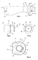
- a handle element 10 is provided.
- the grip element 10 has a projection 12 for supporting the palm of the hand and is attached via a clamping means 14 on the bicycle handlebar.
- a grip element is for example in EP 1 537 014 described.
- an actuating element 18 is arranged on an inner side relative to the handle member 10.
- the actuator 18 is at least partially pivoted about the handlebar 16 around or rotated. This results in switching of an electrical switch for controlling a via a cable 20 connected to the control support motor.
- the connection can also be wireless.
- the rotation of the actuating element 18 takes place in the illustrated embodiment by means of an inserted into a switching recess 22 of the actuating element thumb and moving the thumb up or down.
- the actuating element 18 is mounted on a bearing element 24 (FIG. Fig. 2 ) arranged.
- the bearing element 24 has a the outer diameter of the handlebar 16 having a cylindrical opening 26 (FIG. Fig. 3 ) on.
- a fixing element 28 (FIG. Fig. 1 ) in cooperation with a recess 30 in the bearing element can be made a clamping fixing of the bearing ring on the handlebar 16.
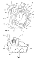
- the actuator 18 is arranged on a in Fig. 2 right or inner side of an annular abutment ring 32.
- An opposite cylindrical part 34 of the bearing element 24th either protrudes directly into the grip element 10 or is partially surrounded by a further substantially cylindrical grip part 36, so that the cylindrical projection 34 projects only partially into the grip element 10.
- further electronic components or the like can be accommodated in the cylindrical grip part 36.
- the actuating element 18 has in the illustrated embodiment, an inner cylindrical, a slider forming approach 38. This surrounds the cylindrical projection 40 of the bearing element 10, so that a rotation or pivoting of the confirmation element 18 on the cylindrical projection 40 of the bearing element 24 according to the arrows 42 is possible.
- the actuation of the actuating element 18 takes place in the illustrated embodiment with the help of the thumb, which is placed in the trough 22.
- two switching lugs 44 are provided in the illustrated embodiment, which protrude into the actuating element 18.
- 18 slots 48 are provided in a side wall 46 of the actuating element.
- a switching element 50 ( Fig. 5 ), For example, made of softer plastic.
- Further switching elements 52 are arranged in the circumferential direction along the outside of a housing 54 forming the actuating element 18.
- the switching elements 52 are arranged in various recesses 56 of the housing 54 and can be pressed inward for switching.
- the switching elements 52 are formed, for example, as a main switch, a light switch and a mode switch for controlling a bicycle computer.
- a plurality of interconnected by a conductor 58 membrane switch 60 are provided within the housing 54 .
- the membrane keys 60 are integrated in particular in the conductor 58, which in particular Fig. 6 is apparent.
- the conductor 58 runs together with the film buttons 60 in the circumferential direction of the housing 54.
- two membrane buttons 60 are also arranged, act on the switching lugs 44 upon rotation of the actuating element 18.
- the conductor track 58 with the integrated membrane buttons 60 is strip-shaped, so that all the membrane buttons 60 are arranged one behind the other in the longitudinal direction.
- the conductor 58 is connected to a plug-in board 62, which is connected in a preferred embodiment via a six-pin connector with the cable 20.
- the conductor track is inserted into the housing 54, wherein the individual membrane buttons 60 are fixed by pins 64 which are in particular formed integrally with the housing.
- a rotation of the confirmation element 18 causes a rotation of the connected to the actuator 18 conductor 58.
- one of the two membrane switches 60 comes into contact with one of the two switching lugs 44, wherein the switching lugs 44 are stationary due to their connection to the bearing element 24. In this way, an electrical contact can be triggered and a corresponding switching signal can be generated.
Landscapes
- Engineering & Computer Science (AREA)
- Chemical & Material Sciences (AREA)
- Combustion & Propulsion (AREA)
- Mechanical Engineering (AREA)
- Transportation (AREA)
- Steering Devices For Bicycles And Motorcycles (AREA)
Applications Claiming Priority (1)
| Application Number | Priority Date | Filing Date | Title |
|---|---|---|---|
| DE202013002491.7U DE202013002491U1 (de) | 2013-03-15 | 2013-03-15 | Fahrradgriff-System |
Publications (1)
| Publication Number | Publication Date |
|---|---|
| EP2778035A1 true EP2778035A1 (fr) | 2014-09-17 |
Family
ID=50272424
Family Applications (1)
| Application Number | Title | Priority Date | Filing Date |
|---|---|---|---|
| EP14159251.9A Withdrawn EP2778035A1 (fr) | 2013-03-15 | 2014-03-12 | Système de poignée de bicyclette |
Country Status (3)
| Country | Link |
|---|---|
| US (1) | US9287063B2 (fr) |
| EP (1) | EP2778035A1 (fr) |
| DE (1) | DE202013002491U1 (fr) |
Cited By (1)
| Publication number | Priority date | Publication date | Assignee | Title |
|---|---|---|---|---|
| US10676156B2 (en) | 2016-08-02 | 2020-06-09 | Campagnolo S.R.L. | Bicycle control device |
Families Citing this family (9)
| Publication number | Priority date | Publication date | Assignee | Title |
|---|---|---|---|---|
| DE202013002490U1 (de) * | 2013-03-15 | 2014-06-17 | Rti Sports Vertrieb Von Sportartikeln Gmbh | Fahrradgriffsystem |
| DE102015216186B4 (de) * | 2015-08-25 | 2017-10-19 | Biketec Ag | Fernbedienungseinheit und Elektrofahrrad |
| JP6965238B2 (ja) | 2015-08-25 | 2021-11-10 | バイクテック アーゲーBiketec Ag | ディスプレイ・ユニットおよび電気自転車 |
| EP3147194B1 (fr) * | 2015-09-22 | 2022-07-20 | SRAM Deutschland GmbH | Dispositif de commande sans fil d'au moins un composant d'un vélo |
| DE102016010801A1 (de) | 2015-09-22 | 2017-03-23 | Sram Deutschland Gmbh | Ansteuereinrichtung zum drahtlosen Ansteuern wenigstens einer Komponente eines Fahrrads |
| US10889346B2 (en) | 2017-08-18 | 2021-01-12 | Shimano Inc. | Electric twist-grip operating device |
| CN110466659B (zh) * | 2019-08-05 | 2020-06-26 | 福州三金机动车配件有限公司 | 一种用于摩托车油门同步的多向开关 |
| DE102020100277A1 (de) * | 2020-01-09 | 2021-07-15 | Shimano Inc. | Betätigungsvorrichtung für ein mit menschenkraft angetriebenes fahrzeug |
| US11618529B2 (en) | 2020-06-03 | 2023-04-04 | Dextera Brakes, Llc | Grip assembly for vehicle |
Citations (10)
| Publication number | Priority date | Publication date | Assignee | Title |
|---|---|---|---|---|
| US6031190A (en) * | 1997-09-08 | 2000-02-29 | Shimano Inc. | Operating mode switching unit for bicycle |
| US6144125A (en) * | 1998-05-11 | 2000-11-07 | Orville J. Birkestrand | Contactless electronic control system for modular motorized wheel hub |
| EP1225123A1 (fr) * | 2001-01-23 | 2002-07-24 | Samuel Y.T. Strong | Accélérateur pour bicyclette électrique |
| DE10143585A1 (de) * | 2001-09-05 | 2003-03-20 | Schauff Hans | Lenkergriff mit integriertem elektronischen Bauteil |
| WO2003024773A1 (fr) * | 2001-09-14 | 2003-03-27 | Song, Seung-Hee | Systeme de commande d'accelerateur pour bicyclette electrique |
| US20050023067A1 (en) * | 2003-08-01 | 2005-02-03 | Ledford Timothy Gerald | Grip actuated vehicle control system |
| WO2005021366A1 (fr) * | 2003-08-25 | 2005-03-10 | Rti Sports Vertrieb Von Sportartikeln | Poignee de bicyclette |
| US20100212978A1 (en) * | 2009-02-23 | 2010-08-26 | Wen-Hung Huang | Bicycle with two operation molds |
| US20110303041A1 (en) * | 2010-06-15 | 2011-12-15 | Wen Feng Cheng | Throttle Twist Grip Controller with Ring Potentiometer Assembly |
| DE102012204189A1 (de) * | 2011-03-18 | 2012-09-20 | Hirschmann Automotive Gmbh | Abschirmung eines Sensors in einem Drehgriff |
Family Cites Families (7)
| Publication number | Priority date | Publication date | Assignee | Title |
|---|---|---|---|---|
| US4356358A (en) * | 1981-07-01 | 1982-10-26 | Amp Incorporated | Membrane switch |
| JP3470820B2 (ja) * | 1993-10-06 | 2003-11-25 | 株式会社シマノ | 自転車用変速装置 |
| US7350436B2 (en) * | 2004-03-29 | 2008-04-01 | Shimano, Inc. | Electrical bicycle shift control device |
| US7406367B2 (en) * | 2004-08-26 | 2008-07-29 | Shimano Inc. | Input circuit for bicycle component |
| US7902967B2 (en) * | 2007-10-23 | 2011-03-08 | Shimano Inc. | Bicycle control system |
| JP5403804B2 (ja) * | 2009-04-28 | 2014-01-29 | 本田技研工業株式会社 | ハンドルスイッチ |
| TWM430424U (en) * | 2011-10-19 | 2012-06-01 | Shimano Kk | Controller for bicycle |
-
2013
- 2013-03-15 DE DE202013002491.7U patent/DE202013002491U1/de not_active Expired - Lifetime
-
2014
- 2014-03-12 EP EP14159251.9A patent/EP2778035A1/fr not_active Withdrawn
- 2014-03-14 US US14/212,071 patent/US9287063B2/en not_active Expired - Fee Related
Patent Citations (11)
| Publication number | Priority date | Publication date | Assignee | Title |
|---|---|---|---|---|
| US6031190A (en) * | 1997-09-08 | 2000-02-29 | Shimano Inc. | Operating mode switching unit for bicycle |
| US6144125A (en) * | 1998-05-11 | 2000-11-07 | Orville J. Birkestrand | Contactless electronic control system for modular motorized wheel hub |
| EP1225123A1 (fr) * | 2001-01-23 | 2002-07-24 | Samuel Y.T. Strong | Accélérateur pour bicyclette électrique |
| DE10143585A1 (de) * | 2001-09-05 | 2003-03-20 | Schauff Hans | Lenkergriff mit integriertem elektronischen Bauteil |
| WO2003024773A1 (fr) * | 2001-09-14 | 2003-03-27 | Song, Seung-Hee | Systeme de commande d'accelerateur pour bicyclette electrique |
| US20050023067A1 (en) * | 2003-08-01 | 2005-02-03 | Ledford Timothy Gerald | Grip actuated vehicle control system |
| WO2005021366A1 (fr) * | 2003-08-25 | 2005-03-10 | Rti Sports Vertrieb Von Sportartikeln | Poignee de bicyclette |
| EP1537014A1 (fr) | 2003-08-25 | 2005-06-08 | RTI Sports Vertrieb von Sportartikeln GmbH | Poignee de bicyclette |
| US20100212978A1 (en) * | 2009-02-23 | 2010-08-26 | Wen-Hung Huang | Bicycle with two operation molds |
| US20110303041A1 (en) * | 2010-06-15 | 2011-12-15 | Wen Feng Cheng | Throttle Twist Grip Controller with Ring Potentiometer Assembly |
| DE102012204189A1 (de) * | 2011-03-18 | 2012-09-20 | Hirschmann Automotive Gmbh | Abschirmung eines Sensors in einem Drehgriff |
Cited By (1)
| Publication number | Priority date | Publication date | Assignee | Title |
|---|---|---|---|---|
| US10676156B2 (en) | 2016-08-02 | 2020-06-09 | Campagnolo S.R.L. | Bicycle control device |
Also Published As
| Publication number | Publication date |
|---|---|
| US9287063B2 (en) | 2016-03-15 |
| DE202013002491U1 (de) | 2014-06-17 |
| US20140260753A1 (en) | 2014-09-18 |
Similar Documents
| Publication | Publication Date | Title |
|---|---|---|
| EP2778035A1 (fr) | Système de poignée de bicyclette | |
| DE102016010801A1 (de) | Ansteuereinrichtung zum drahtlosen Ansteuern wenigstens einer Komponente eines Fahrrads | |
| EP2682332B1 (fr) | Système de poignée de vélo | |
| EP3147194B1 (fr) | Dispositif de commande sans fil d'au moins un composant d'un vélo | |
| EP1695868B1 (fr) | Interrupteur multifonction à bouton poussoir | |
| DE69408418T2 (de) | Hebelschaltervorrichtung, Verfahren zur Steuerung von Schaltern in solcher Vorrichtung und Verfahren zum Ausgeben von Datensignalen | |
| EP0228599B1 (fr) | Fixation de ski avec commande à distance sans fil | |
| DE4230647B4 (de) | Schalteranordnung | |
| EP0886289B1 (fr) | Commutateur électrique rotatif à poussoir | |
| EP2703275B1 (fr) | Poignée de bicyclette | |
| DE102016004329A1 (de) | Vorrichtung zum Schalten einer elektrischen Fahrradkomponente | |
| EP2093785A1 (fr) | Commutateur multi-fonctions | |
| WO2015161389A1 (fr) | Commutateur | |
| EP2778037A1 (fr) | Système de poignée de bicyclette | |
| WO2005092698A1 (fr) | Element de commande | |
| EP2778036A1 (fr) | Sytème de poignée de bicyclette | |
| EP0887819B1 (fr) | Commutateur électrique à bouton poussoir | |
| DE102005038145A1 (de) | Lenksäulenmodul | |
| DE102004031309B4 (de) | Lenkrad mit einem Bedienelement | |
| DE202012007991U1 (de) | Fahrradgriffsystem | |
| DE69329971T2 (de) | Schalterhebel für eine Lenksäule | |
| EP1473748B1 (fr) | Boîtier comprenant plusieurs commutateurs et une commande à distance autonome en énergie | |
| DE202012012338U1 (de) | Fahrradgriffsystem | |
| AT511104B1 (de) | Bedienelement | |
| EP0893303B1 (fr) | Interrupteur sur colonne de direction |
Legal Events
| Date | Code | Title | Description |
|---|---|---|---|
| 17P | Request for examination filed |
Effective date: 20140312 |
|
| AK | Designated contracting states |
Kind code of ref document: A1 Designated state(s): AL AT BE BG CH CY CZ DE DK EE ES FI FR GB GR HR HU IE IS IT LI LT LU LV MC MK MT NL NO PL PT RO RS SE SI SK SM TR |
|
| AX | Request for extension of the european patent |
Extension state: BA ME |
|
| PUAI | Public reference made under article 153(3) epc to a published international application that has entered the european phase |
Free format text: ORIGINAL CODE: 0009012 |
|
| R17P | Request for examination filed (corrected) |
Effective date: 20150312 |
|
| RBV | Designated contracting states (corrected) |
Designated state(s): AL AT BE BG CH CY CZ DE DK EE ES FI FR GB GR HR HU IE IS IT LI LT LU LV MC MK MT NL NO PL PT RO RS SE SI SK SM TR |
|
| 17Q | First examination report despatched |
Effective date: 20151119 |
|
| RAP1 | Party data changed (applicant data changed or rights of an application transferred) |
Owner name: RTI SPORTS GMBH |
|
| STAA | Information on the status of an ep patent application or granted ep patent |
Free format text: STATUS: EXAMINATION IS IN PROGRESS |
|
| STAA | Information on the status of an ep patent application or granted ep patent |
Free format text: STATUS: THE APPLICATION IS DEEMED TO BE WITHDRAWN |
|
| 18D | Application deemed to be withdrawn |
Effective date: 20161001 |