EP2778039A1 - Dispositif de fourniture d'air pour navire lubrifié par l'air - Google Patents
Dispositif de fourniture d'air pour navire lubrifié par l'air Download PDFInfo
- Publication number
- EP2778039A1 EP2778039A1 EP12844460.1A EP12844460A EP2778039A1 EP 2778039 A1 EP2778039 A1 EP 2778039A1 EP 12844460 A EP12844460 A EP 12844460A EP 2778039 A1 EP2778039 A1 EP 2778039A1
- Authority
- EP
- European Patent Office
- Prior art keywords
- pressure
- air
- path
- increasing
- flow rate
- Prior art date
- Legal status (The legal status is an assumption and is not a legal conclusion. Google has not performed a legal analysis and makes no representation as to the accuracy of the status listed.)
- Granted
Links
Images



Classifications
-
- B—PERFORMING OPERATIONS; TRANSPORTING
- B63—SHIPS OR OTHER WATERBORNE VESSELS; RELATED EQUIPMENT
- B63B—SHIPS OR OTHER WATERBORNE VESSELS; EQUIPMENT FOR SHIPPING
- B63B1/00—Hydrodynamic or hydrostatic features of hulls or of hydrofoils
- B63B1/32—Other means for varying the inherent hydrodynamic characteristics of hulls
- B63B1/34—Other means for varying the inherent hydrodynamic characteristics of hulls by reducing surface friction
- B63B1/38—Other means for varying the inherent hydrodynamic characteristics of hulls by reducing surface friction using air bubbles or air layers gas filled volumes
-
- B—PERFORMING OPERATIONS; TRANSPORTING
- B63—SHIPS OR OTHER WATERBORNE VESSELS; RELATED EQUIPMENT
- B63H—MARINE PROPULSION OR STEERING
- B63H21/00—Use of propulsion power plant or units on vessels
- B63H21/12—Use of propulsion power plant or units on vessels the vessels being motor-driven
- B63H21/14—Use of propulsion power plant or units on vessels the vessels being motor-driven relating to internal-combustion engines
-
- F—MECHANICAL ENGINEERING; LIGHTING; HEATING; WEAPONS; BLASTING
- F02—COMBUSTION ENGINES; HOT-GAS OR COMBUSTION-PRODUCT ENGINE PLANTS
- F02B—INTERNAL-COMBUSTION PISTON ENGINES; COMBUSTION ENGINES IN GENERAL
- F02B37/00—Engines characterised by provision of pumps driven at least for part of the time by exhaust
- F02B37/12—Control of the pumps
- F02B37/16—Control of the pumps by bypassing charging air
- F02B37/164—Control of the pumps by bypassing charging air the bypassed air being used in an auxiliary apparatus, e.g. in an air turbine
-
- Y—GENERAL TAGGING OF NEW TECHNOLOGICAL DEVELOPMENTS; GENERAL TAGGING OF CROSS-SECTIONAL TECHNOLOGIES SPANNING OVER SEVERAL SECTIONS OF THE IPC; TECHNICAL SUBJECTS COVERED BY FORMER USPC CROSS-REFERENCE ART COLLECTIONS [XRACs] AND DIGESTS
- Y02—TECHNOLOGIES OR APPLICATIONS FOR MITIGATION OR ADAPTATION AGAINST CLIMATE CHANGE
- Y02T—CLIMATE CHANGE MITIGATION TECHNOLOGIES RELATED TO TRANSPORTATION
- Y02T10/00—Road transport of goods or passengers
- Y02T10/10—Internal combustion engine [ICE] based vehicles
- Y02T10/12—Improving ICE efficiencies
-
- Y—GENERAL TAGGING OF NEW TECHNOLOGICAL DEVELOPMENTS; GENERAL TAGGING OF CROSS-SECTIONAL TECHNOLOGIES SPANNING OVER SEVERAL SECTIONS OF THE IPC; TECHNICAL SUBJECTS COVERED BY FORMER USPC CROSS-REFERENCE ART COLLECTIONS [XRACs] AND DIGESTS
- Y02—TECHNOLOGIES OR APPLICATIONS FOR MITIGATION OR ADAPTATION AGAINST CLIMATE CHANGE
- Y02T—CLIMATE CHANGE MITIGATION TECHNOLOGIES RELATED TO TRANSPORTATION
- Y02T70/00—Maritime or waterways transport
- Y02T70/10—Measures concerning design or construction of watercraft hulls
Definitions
- the present invention relates to an air supply apparatus of an air lubrication type ship for reducing friction resistance of water along a ship's bottom outer surface of a ship during marine navigation.
- a ship receives friction resistance of water during marine navigation on its submerged surface of a ship's bottom.
- most portion of resistance of ship's hull is derived from friction resistance generated by relative flow of outside water in the ship's bottom.
- Patent document 1 and patent document 2 propose an apparatus which utilizes scavenging gas which is pressurized air existing between an inter-cooler and a main engine.
- Patent document 3 and patent document 4 propose an apparatus which utilizes exhaust gas of a main engine.
- Patent document 5 proposes an apparatus which utilizes low pressure pressurized air extracted from a low pressure location of a turbocharger.
- Patent document 6 proposes an apparatus which utilizes pressurized air and/or exhaust gas existing between a turbocharger and a main engine.
- Patent document 7 proposes an apparatus including compressed gas supply means which is rotated and driven by exhaust gas, and this apparatus utilizes compressed gas of the compressed gas supply means.
- Pressurized air pressure (scavenging pressure) supplied by a turbocharger to a main engine is proportional to output of the main engine. That is, there exist such characteristics that when a main engine load is low, the pressurized air pressure is low and when the main engine load is high, the pressurized air pressure becomes high. Exhaust gas also has similar characteristics that exhaust gas is proportional to output of the main engine.
- draft is varied depending upon a loaded state.
- scavenging pressure of the main engine becomes lower than draft pressure, and air lubrication can not be applied in some cases.
- patent document 1 to patent document 7 do not disclose to widen a region in which air lubrication can be applied or do not disclose to take energy efficiency into consideration.
- an object of the present invention to provide an air supply apparatus of an air lubrication type ship in which even if pressurized air pressure supplied to a main engine by a turbocharger is varied by output of the main engine and even if draft pressure is varied due to a loaded state, the air supply apparatus can increase the pressurized air pressure and can eject the pressurized air in accordance with the variations.
- the present invention it is possible to provide an air supply apparatus of an air lubrication type ship having high energy efficiency and capable of enhancing
- a first aspect of the invention provides an air supply apparatus of an air lubrication type ship which ejects air to surroundings of a ship's hull to reduce friction resistance, the air supply apparatus comprising a turbocharger which supplies pressurized air to a main engine of the air lubrication type ship, taking-out means which takes out a portion of the pressurized air, pressure-increasing means which further increases pressure of the pressurized air which is taken out by the taking-out means, a pressure-increasing path through which pressure-increased air whose pressure is increased by the pressure-increasing means is supplied, a bypass path which bypasses the pressure-increasing means, and path selecting means which selects the pressure-increasing path and the bypass path, wherein the path selecting means selects the pressure-increasing path and/or the bypass path to supply the pressure-increased air and/or the pressurized air and eject the same to the surroundings of the ship's hull.
- the bypass path when the bypass path is selected, air is ejected to the surroundings of the ship's hull using pressurized air which is supplied to the main engine, and when the pressure-increasing path is selected, it is possible to eject air to the surroundings of the ship's hull using pressure-increased air obtained by further increasing pressure of the pressurized air by the pressure-increasing means. That is, it is possible to select ejection carried out only by pressurized air and ejection using pressure-increased air which is assisted by the pressure-increasing means.
- pressurized air used in this application also includes air which is pressurized in the turbocharger contributes to combustion in the main engine and which becomes pressurized exhaust gas.
- the air supply apparatus further includes at least one more pressure-increasing means, at least one more pressure-increasing path and at least one more path selecting means, and the pressure-increased air can be supplied by operation of an arbitrary number of the pressure-increasing means.
- the air supply apparatus further includes at least one more pressure-increasing means, at least one more pressure-increasing path and at least one more path selecting means, and the pressure-increased air can be supplied by operation of an arbitrary number of the pressure-increasing means.
- the pressure-increasing means is further provided with atmosphere taking-in means which takes in air from atmosphere, and pressure of the air from the atmosphere can be increased and the air can be supplied.
- atmosphere taking-in means which takes in air from atmosphere
- pressure of the air from the atmosphere can be increased and the air can be supplied.
- the path selecting means selects the bypass path, the pressurized air is supplied through the bypass path while bypassing the pressure-increasing means, and the atmosphere taking-in means is controlled, then pressure of air from the atmosphere is increased and the air is supplied through the pressure-increasing path.
- pressurized air is supplied through the bypass path, and air from the atmosphere is supplied through the pressure-increasing path. Therefore, it is possible to increase an ejection amount of air to the surroundings of the ship's hull, to enhance the friction reducing effect, and to further enhance the energy saving effect.
- the pressurized air which is taken out by the taking-out means is scavenging gas as a portion of the pressurized air sent from a compressor which configures the turbocharger to the main engine. According to this aspect, by utilizing the scavenging gas, it is possible to reduce energy which is required for the pressure-increasing means.
- the air supply apparatus further includes draft detecting means which detects draft of the ship's hull and control means which controls the path selecting means and the pressure-increasing means, and the control means carries out control based on a detection result of the draft detecting means.
- the draft detecting means can detect variation in draft pressure caused by a loaded state, and the control means can control in accordance with draft pressure so that pressurized air and pressure-increased air can appropriately be combined with each other and they can be supplied, and it is possible to accurately set a condition under which the air lubrication can be applied. Therefore, it is possible to select an air supply method which becomes that condition and which has high energy efficiency.
- the air supply apparatus further includes load detecting means which detects a load of the main engine, and the control means carries out control based on a detection result of the load detecting means.
- the load detecting means can detect variation in pressurized air pressure caused by output of the main engine, and the control means carries out control in accordance with pressurized air pressure. Therefore, it is possible to select an air supply method which becomes that condition and which has high energy efficiency.
- the load detecting means detects scavenging gas pressure of the turbocharger. According to this aspect, by detecting variation caused by output of the main engine by means of scavenging gas pressure, it is possible to detect variation in pressurized air pressure without time lag. Hence, it is possible to carry out control to follow variation in a load. Therefore, it is possible to enhance the energy efficiency.
- the air supply apparatus further includes a flow rate adjusting valve which is located between the turbocharger and the pressure-increasing means and which adjusts a flow rate of the pressurized air.
- the air supply apparatus includes the flow rate adjusting valve. Therefore, it is possible to moderate flow rate variation caused by influence of an operation state of the pressure-increasing means, and to stabilize a supply flow rate of pressurized air from the turbocharger to the main engine. Therefore, it is possible to prevent energy efficiency of the main engine from being deteriorated.
- the air supply apparatus further includes flow rate detecting means which detects a flow rate of the pressurized air from the turbocharger to the pressure-increasing means. According to this aspect, since the air supply apparatus includes the flow rate detecting means, it is possible to stably control a flow rate of pressurized air.
- a flow rate detection value detected by the flow rate detecting means is fed back to control the flow rate adjusting valve.
- control for taking out pressurized air in accordance with the set flow rate can be carried out, and it is possible to appropriately maintain a pressurized air amount to the main engine, and to effectively enhance a pressure increasing operation in the pressure-increasing means. Further, even if any trouble is generated in the pressure-increasing means, since scavenging pressure can be adjusted by the flow rate adjusting valve, influence of this trouble is not exerted to the main engine, and a safety level is high.
- an opening degree of the flow rate adjusting valve or a flow rate detection value detected by the flow rate detecting means is fed back to control the pressure-increasing means. According to this aspect, it is possible to control the pressure-increasing means in accordance with a set opening degree or a set flow rate, and a predetermined flow rate can be obtained.
- a blower whose rotational speed can be controlled is used as the pressure-increasing means. According to this aspect, it is possible to carry out the pressure-increasing adjustment by the blower in accordance with variation in pressurized air pressure or draft pressure.
- the rotational speed of the blower is detected, and a detected rotational speed detection value is fed back to control the blower. According to this aspect, since it is possible to carry out control based on the rotational speed of the blower, and it is possible to carry out control without carrying out detection of the flow rate detecting means and the like.
- the air supply apparatus further includes ship's hull movement detecting means which detects movement of the ship' s hull, and a ship' s hull movement detection value of the ship's hull movement detecting means is fed forward to control the flow rate adjusting valve and/or the pressure-increasing means.
- the air supply apparatus since the air supply apparatus includes the ship's hull movement detecting means, it is possible to forecast variation of draft or the like from the ship's hull movement detection value, to change the combination of pressurized air and pressure-increased air, and to control a flow rate.
- the air supply apparatus includes the plurality of pressure-increasing means, the plurality of pressure-increasing path and the plurality of path selecting means, and if pressure-increased air can be supplied by operation of an arbitrary number of pressure-increasing means, it is possible to increase pressure of the pressurized air and to eject the pressurized air in accordance with variation in pressurized air pressure and variation in draft pressure by switching the plurality of pressure-increasing means. Therefore, it is possible to further enhance the energy efficiency and the energy saving effect.
- the pressure-increasing means is further provided with the atmosphere taking-in means for taking in air from atmosphere and pressure of air from the atmosphere can be increased and supplied, the bypass path supplies pressurized air, and the pressure-increasing path supplies air from the atmosphere. Therefore, it is possible to increase an ejection amount of air to the surroundings of the ship' s hull, to enhance the friction reducing effect, and to further enhance the energy saving effect.
- the path selecting means selects the bypass path, the pressurized air is supplied through the bypass path while bypassing the pressure-increasing means, and the atmosphere taking-in means is controlled, then pressure of air from the atmosphere is increased and the air is supplied through the pressure-increasing path. According to this, pressurized air is supplied through the bypass path, and air from the atmosphere is supplied through the pressure-increasing path. Therefore, it is possible to increase an ejection amount of air to the surroundings of the ship's hull, to enhance the friction reducing effect, and to further enhance the energy saving effect.
- the pressurized air which is taken out by the taking-out means is scavenging gas as a portion of the pressurized air sent from a compressor which configures the turbocharger to the main engine. According to this, by utilizing the scavenging gas, it is possible to reduce energy which is required for the pressure-increasing means.
- the air supply apparatus further includes draft detecting means which detects draft of the ship's hull and control means which controls the path selecting means and the pressure-increasing means, and the control means carries out control based on a detection result of the draft detecting means.
- the draft detecting means can detect variation in draft pressure caused by a loaded state, and the control means can control in accordance with draft pressure so that pressurized air and pressure-increased air can appropriately be combined with each other and they can be supplied, and it is possible to accurately set a condition under which the air lubrication can be applied. Therefore, it is possible to select an air supply method which becomes that condition and which has high energy efficiency.
- the air supply apparatus further includes load detecting means which detects a load of the main engine, and the control means carries out control based on a detection result of the load detecting means.
- the load detecting means can detect variation in pressurized air pressure caused by output of the main engine, and the control means carries out control in accordance with pressurized air pressure. Therefore, it is possible to select an air supply method which becomes that condition and which has high energy efficiency.
- the load detecting means detects scavenging gas pressure of the turbocharger. According to this, by detecting variation caused by output of the main engine by means of scavenging gas pressure, it is possible to detect variation in pressurized air pressure without time lag. Hence, it is possible to carry out control to follow variation in a load. Therefore, it is possible to enhance the energy efficiency.
- the air supply apparatus further includes a flow rate adjusting valve which is located between the turbocharger and the pressure-increasing means and which adjusts a flow rate of the pressurized air.
- the air supply apparatus includes the flow rate adjusting valve. Therefore, it is possible to moderate flow rate variation caused by influence of an operation state of the pressure-increasing means, and to stabilize a supply flow rate of pressurized air from the turbocharger to the main engine. Therefore, it is possible to prevent energy efficiency of the main engine from being deteriorated.
- the air supply apparatus further includes flow rate detecting means which detects a flow rate of the pressurized air from the turbocharger to the pressure-increasing means. According to this, since the air supply apparatus includes the flow rate detecting means, it is possible to stably control a flow rate of pressurized air.
- a flow rate detection value detected by the flow rate detecting means is fed back to control the flow rate adjusting valve.
- control for taking out pressurized air in accordance with the set flow rate can be carried out, and it is possible to appropriately maintain a pressurized air amount to the main engine, and to effectively enhance a pressure increasing operation in the pressure-increasing means.
- a flow rate is set while maintaining margin so that such an opening degree that the flow rate adjusting valve is not fully opened, control to compensate variation of the pressure-increasing means is carried out by the flow rate adjusting valve, and a flow rate can be stabilized.
- An opening degree of the flow rate adjusting valve or a flow rate detection value detected by the flow rate detecting means is fed back to control the pressure-increasing means. According to this, it is possible to control the pressure-increasing means in accordance with a set opening degree or a set flow rate, and a predetermined flow rate can be obtained.
- a blower whose rotational speed can be controlled is used as the pressure-increasing means. According to this, it is possible to carry out the pressure-increasing adjustment by the blower in accordance with variation in pressurized air pressure or draft pressure.
- the rotational speed of the blower is detected, and a detected rotational speed detection value is fed back to control the blower. According to this, since it is possible to carry out control based on the rotational speed of the blower, and it is possible to carry out control without carrying out detection of the flow rate detecting means and the like.
- the air supply apparatus further includes ship's hull movement detecting means which detects movement of the ship' s hull, and a ship's hull movement detection value of the ship's hull movement detecting means is fed forward to control the flow rate adjusting valve and/or the pressure-increasing means. According to this, since the air supply apparatus includes the ship's hull movement detecting means, it is possible to forecast variation of draft or the like from the ship's hull movement detection value, to change the combination of pressurized air and pressure-increased air, and to control a flow rate.
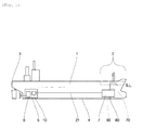
- Fig. 1 is a schematic block diagram of the air lubrication type ship provided with the air supply apparatus according to the embodiment of the invention.
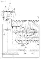
- Figs. 2 to 4 are schematic block diagrams of the air supply apparatus of the air lubrication type ship.
- Fig. 2 shows path which increase pressure of scavenging bypass gas to eject the same from an air supply port.
- Fig. 3 shows paths which eject scavenging bypass gas from an air supply port without increasing pressure of the scavenging bypass gas.
- Fig. 4 shows paths which separately eject scavenging bypass gas and air taken in from atmosphere from an air supply port.
- the air lubrication type ship of the embodiment includes an air supply apparatus 7 (main part) on the side of a stem portion 2 of a ship's hull 1, and a drive source 5 which drives a propeller on the side of a stern 3.
- the ship's bottom 4 of the stem portion 2 is provided with an air supply port 80. If air is ejected as air bubbles to surroundings of a ship's bottom 4 of the ship's hull 1 from the air supply port 80 is possible to supply air bubbles to a wide region of the ship's bottom 4 below a sea level S.L., and it is possible to obtain a high friction resistance reducing effect.
- an air path 90 reaching the air supply port 80 can be shortened. Therefore, it is possible to suppress a pressure loss in the air path 90, and to efficiently supply air to the air supply port 80.
- the air supply port 80 may be provided on a side surface of the stem close to the ship's bottom 4, the ship's bottom 4 at which a width of the ship's hull 1 starts narrowing, or a side surface of the ship's hull 1.
- the drive source 5 includes a main engine 6 which is an internal combustion engine, and a turbocharger 10 which supplies pressurized air to the main engine 6 and which is driven by exhaust gas of the main engine 6.
- a portion of pressurized air before it is supplied to the main engine 6 is sent to the air supply apparatus 7 through a taking-out path 21.
- the air supply apparatus 7 is provided with an atmosphere taking-in path 70 through which air is taken in from atmosphere.
- a portion of pressurized air is introduced into the air supply apparatus 7 (main part) from the taking-out path 21.
- the turbocharger 10 includes a turbine 11 which takes out power from an exhaust path of the main engine 6, a compressor 12 which is operated by the turbine 11, and a scavenging receiver 13 which introduces air pressurized by the compressor 12 into a cylinder of the main engine 6.
- One end of the taking-out path 21 is connected to the scavenging receiver 13. Pressurized air is introduced into the taking-out path 21 from the scavenging receiver 13.
- the other end of the taking-out path 21 is branched into three paths. Each of the path ends is provided with a first on-off valve 61a, a second on-off valve 61b and a third on-off valve 63.
- the taking-out path 21 is provided with a flow rate adjusting valve 22 which adjusts a flow rate of pressurized air, and flow rate detecting means 31 which detects a flow rate of pressurized air.
- the flow rate adjusting valve 22 is fed back using a flow rate detection value detected by the flow rate detecting means 31 and is PID controlled.
- a flow rate detection value detected by the flow rate detecting means 31 is compared with a set value SP by a valve-controller 32, and the valve-controller 32 gives an operation signal to the flow rate adjusting valve 22 such that the flow rate detection value approaches the set value SP.
- the set value SP which is input to the valve-controller 32 sets an optimal flow rate that is suitable for output of the main engine for example.
- Taking-out means is composed of the taking-out path 21, the flow rate adjusting valve 22, the flow rate detecting means 31 and the valve-controller 32.
- a blower controller 33 feeds back a flow rate detection value detected by an opening degree of the flow rate adjusting valve 22, and controls first pressure-increasing means 30a.
- the flow rate detection value detected by the flow rate adjusting valve 22 is compared with a set value by the blower controller 33, and the blower controller 33 controls the rotational speed (rotational frequency) of the first pressure-increasing means 30a such that the flow rate detection value approaches the set value SP.
- the set value SP which is input to the blower controller 33 sets a constant (given) value in a range of 80 to 95% of the opening degree for example.
- a first pressure-increasing path 41a is provided at its one end with the first on-off valve 61a and at its other end with a fourth on-off valve 62a.
- the first pressure-increasing path 41a is provided with the first pressure-increasing means 30a which further increases pressure of pressurized air which is taken out by the taking-out means.
- the first pressure-increasing path 41a supplies air whose pressure is increased by the first pressure-increasing means 30a.
- a second pressure-increasing path 41b is provided at its one end with a second on-off valve 61b and at its other end with a fifth on-off valve 62b.
- the second pressure-increasing path 41b is provided with second pressure-increasing means 30b which further increases pressure of pressurized air taken out by the taking-out means.
- the second pressure-increasing path 41b supplies pressure-increased air whose pressure is increased by the second pressure-increasing means 30b.
- a bypass path 51 which bypasses the first pressure-increasing means 30a and the second pressure-increasing means 30b is connected to a third on-off valve 63.
- the path selecting means which selects the first pressure-increasing path 41a and the bypass path 51 is composed of the first on-off valve 61a, the third on-off valve 63 and the fourth on-off valve 62a.
- Path selecting means which selects the second pressure-increasing path 41b and the bypass path 51 is composed of the second on-off valve 61b, the third on-off valve 63 and the fifth on-off valve 62b.
- the path selecting means can include setting means which sets path selection and control means which controls the path selection.
- a first atmosphere taking-in path 71a is connected to the first pressure-increasing path 41a which connects the first on-off valve 61a and the first pressure-increasing means 30a to each other.
- One end of the first atmosphere taking-in path 71a opens into atmosphere and the other end thereof is connected to the first pressure-increasing path 41a.
- the first atmosphere taking-in path 71a is provided with a sixth on-off valve 72a.
- a first atmosphere path 73a is connected to the first pressure-increasing path 41a which connects the first pressure-increasing means 30a and the fourth on-off valve 62a to each other.
- One end of the first atmosphere path 73a is connected to the first pressure-increasing path 41a and the other end there of is connected to a seventh on-off valve 74a.
- the atmosphere taking-in means which takes in air from atmosphere into the first pressure-increasing means 30a is composed of the first atmosphere taking-in path 71a and the sixth on-off valve 72a.
- a second atmosphere taking-in path 71b is connected to the second pressure-increasing path 41b which connects the second on-off valve 61b and the second pressure-increasing means 30b to each other.
- One end of the second atmosphere taking-in path 71b opens into atmosphere and the other end thereof is connected to the second pressure-increasing path 41b.
- the second atmosphere taking-in path 71b is provided with an eighth on-off valve 72b.
- a second atmosphere path 73b is connected to the second pressure-increasing path 41b which connects the second pressure-increasing means 30b and the fifth on-off valve 62b to each other.
- One end of the second atmosphere path 73b is connected to the second pressure-increasing path 41b and the other end thereof is connected to a ninth on-off valve 74b.
- Atmosphere taking-in means which takes in air from atmosphere into the second pressure-increasing means 30b is composed of the second atmosphere taking-in path 71b and the eighth on-off valve 72b.
- the air supply port 80 shown in Fig. 1 is composed of an S1 starboard-side supply port 81, an S2 starboard-side supply port 82, an S3 starboard-side supply port 83, a P1 port-side supply port 84, a P2 port-side supply port 85, and a P3 port-side supply port 86.
- An S1 supply path 91 is connected to the S1 starboard-side supply port 81.
- An S2 supply path 92 is connected to the S2 starboard-side supply port 82.
- An S3 supply path 93 is connected to the S3 starboard-side supply port 83.
- a P1 supply path 94 is connected to the P1 port-side supply port 84.
- a P2 supply path 95 is connected to the P2 port-side supply port 85.
- a P3 supply path 96 is connected to the P3 port-side supply port 86.
- the S1 supply path 91 is provided with an S1 on-off valve 101.
- the S2 supply path 92 is provided with an S2 on-off valve 102.
- the S3 supply path 93 is provided with an S3 on-off valve 103.
- the P1 supply path 94 is provided with a P1 on-off valve 104.
- the P2 supply path 95 is provided with a P2 on-off valve 105.
- the P3 supply path 96 is provided with a P3 on-off valve 106.
- An outflow side path of the fourth on-off valve 62a branches into a plurality of paths, and is connected to the S1 supply path 91, the S2 supply path 92, the S3 supply path 93, the P1 supply path 94, the P2 supply path 95 and the P3 supply path 96.
- An outflow side path of the fifth on-off valve 62b branches into a plurality of paths, and is connected to the S1 supply path 91, the S2 supply path 92, the S3 supply path 93, the P1 supply path 94, the P2 supply path 95 and the P3 supply path 96.
- An outflow side path of the bypass path 51 branches into a plurality of paths, and is connected to the S1 supply path 91, the S2 supply path 92, the S3 supply path 93, the P1 supply path 94, the P2 supply path 95 and the P3 supply path 96.
- An outflow side path 75a of the seventh on-off valve 74a is connected to the S1 starboard-side supply port 81.
- An outflow side path 75b of the ninth on-off valve 74b is connected to the P1 port-side supply port 84.
- the air supply apparatus 7 further includes control means 110 which controls the taking-out means, the path selecting means, the first pressure-increasing means 30a and the atmosphere taking-in means.
- the air supply apparatus 7 further includes draft detecting means 111 which detects draft of the ship's hull 1, load detecting means 112 which detects a load of the main engine 6, and ship's hull movement detecting means 113 which detects movement of the ship's hull 1.
- the load detecting means 112 detects a load based on scavenging gas pressure of the turbocharger 10.
- the control means 110 carries out control based on a result of detection of at least one of the draft detecting means 111, the load detecting means 112 and the ship's hull movement detecting means 113.
- the ship's hull movement detection value of the ship's hull movement detecting means 113 can control the flow rate adjusting valve 22 and/or the first pressure-increasing means 30a by feedforward.
- feedforward control variation of draft or the like is forecasted from a ship' s hull movement detection value to control the flow rate adjusting valve 22 and the first pressure-increasing means 30a, and it is possible to control an air supply system which relatively slowly responds without reply delay.
- rough and quick control is carried out by feedforward control and fine control is carried out by feedback control.
- Fig. 2 shows only control concerning the first pressure-increasing means 30a, but the second pressure-increasing means 30b can also be controlled based on a similar configuration.
- the blower controller 33 can be provided with a control function. It is preferable that blowers whose rotational speed can be controlled are used for the first pressure-increasing means 30a and the second pressure-increasing means 30b.
- Fig. 2 shows paths which increase pressure of scavenging bypass gas and eject the same from the air supply port.
- Pressurized air from the taking-out path 21 is guided into the first pressure-increasing path 41a by the path selecting means, and pressure thereof is increased by the first pressure-increasing means 30a. Thereafter, the pressurized air is guided into the S1 supply path 91, the S2 supply path 92, the P1 supply path 94 and the P2 supply path 95, and is ejected from the S1 starboard-side supply port 81, the S2 starboard-side supply port 82, the P1 port-side supply port 84 and the P2 port-side supply port 85.
- the path selecting means opens the first on-off valve 61a and the fourth on-off valve 62a, and closes the second on-off valve 61b, the third on-off valve 63 and the fifth on-off valve 62b, thereby guiding pressurized air from the taking-out path 21 into the first pressure-increasing path 41a.
- the paths shown in Fig. 2 are effective when the ship is fully loaded and output of the main engine 6 is low. That is, when the ship is fully loaded, draft pressure becomes high, and when pressurized air pressure supplied to the main engine 6 is lowered, if pressure-increased air assisted by the first pressure-increasing means 30a is ejected, it is possible to eject air which reduces friction resistance.
- a rise of draft pressure is detected by the draft detecting means 111, reduction in pressurized air pressure supplied to the main engine 6 is detected by the load detecting means 112.
- the control means 110 controls the path selecting means, other on-off valves, the first pressure-increasing means 30a and the second pressure-increasing means 30b, and the first pressure-increasing means 30a is assisted.
- Fig. 3 shows paths which eject scavenging bypass gas from the air supply port without increasing pressure of the scavenging bypass gas.
- Pressurized air from the taking-out path 21 is guided into the bypass path 51 by the path selecting means. Thereafter, the pressurized air is guided into the S1 supply path 91, the S2 supply path 92, the P1 supply path 94 and the P2 supply path 95, and the pressurized air is ejected from the S1 starboard-side supply port 81, the S2 starboard-side supply port 82, the P1 port-side supply port 84 and the P2 port-side supply port 85.
- the path selecting means closes the first on-off valve 61a, the fourth on-off valve 62a, the second on-off valve 61b and the fifth on-off valve 62b, and opens the third on-off valve 63, thereby guiding the pressurized air from the taking-out path 21 into the bypass path 51.
- the pressurized air is ejected from the S1 starboard-side supply port 81, the S2 starboard-side supply port 82, the P1 port-side supply port 84 and the P2 port-side supply port 85. Therefore, the S1 on-off valve 101, the S2 on-off valve 102, the P1 on-off valve 104 and the P2 on-off valve 105 are opened, and the S3 on-off valve 103 and the P3 on-off valve 106 are closed.
- the paths shown in Fig. 3 are effective when the ship is fully loaded and the output of the main engine 6 is high. That is, when the ship is fully loaded, draft pressure becomes high, but when pressurized air pressure supplied to the main engine 6 is high, pressurized air can be ejected without carrying out the assist by the first pressure-increasing means 30a, and it is possible to eject air which reduces friction resistance.
- a rise of draft pressure is detected by the draft detecting means 111, and pressurized air pressure supplied to the main engine 6 is detected by the load detecting means 112.
- the control means 110 controls the path selecting means, other on-off valves, the first pressure-increasing means 30a and the second pressure-increasing means 30b, and the first pressure-increasing means 30a is not assisted.
- Fig. 4 shows paths which separately eject scavenging bypass gas and air taken in from atmosphere from an air supply port.
- Pressurized air from the taking-out path 21 is guided into the bypass path 51 by the path selecting means. Thereafter, the pressurized air is guided into the S2 supply path 92, the S3 supply path 93, the P2 supply path 95 and the P3 supply path 96, and the pressurized air is ejected from the S2 starboard-side supply port 82, the S3 starboard-side supply port 83, the P2 port-side supply port 85 and the P3 port-side supply port 86.
- Air introduced from one end of the first atmosphere taking-in path 71a is guided into the first pressure-increasing path 41a, its pressure is increased by the first pressure-increasing means 30a and then, the air is guided into the first atmosphere path 73a and the outflow side path 75a and is ejected from the S1 starboard-side supply port 81.
- Air introduced from one end of the second atmosphere taking-in path 71b is guided into the second pressure-increasing path 41b, pressure thereof is increased by the second pressure-increasing means 30b and then, the air is guided into the second atmosphere path 73b and the outflow side path 75b and is ejected from the P1 port-side supply port 84.
- the path selecting means closes the first on-off valve 61a, the fourth on-off valve 62a, the second on-off valve 61b and the fifth on-off valve 62b, and opens the third on-off valve 63, thereby guiding pressurized air from the taking-out path 21 into the bypass path 51.
- the sixth on-off valve 72a, the seventh on-off valve 74a, the eighth on-off valve 72b and the ninth on-off valve 74b are opened.
- Pressurized air is ejected from the S2 starboard-side supply port 82, the S3 starboard-side supply port 83, the P2 port-side supply port 85 and the P3 port-side supply port 86. Therefore, the S2 on-off valve 102, the S3 on-off valve 103, the P2 on-off valve 105 and the P3 on-off valve 106 are opened, and the S1 on-off valve 101 and the P1 on-off valve 104 are closed.
- the paths shown in Fig. 4 are effective when the ship has no load and ballast water is supplied into a ballast tank. That is, since draft pressure becomes low when the ship has no load and ballast water is supplied into a ballast tank, pressurized air supplied to the main engine 6 can be ejected without carrying out the assist by the first pressure-increasing means 30a, and it is possible to eject air which reduces friction resistance. Since draft pressure is low when the ship has no load and ballast water is supplied into a ballast tank, large energy is not required for operating the first pressure-increasing means 30a and the second pressure-increasing means 30b.
- the path selecting means, the other on-off valves, the first pressure-increasing means 30a and the second pressure-increasing means 30b are controlled by the control means 110, the scavenging bypass gas is discharged and air taken in from atmosphere is also ejected.
- a lateral axis shows scavenging pressure (Ps) and a vertical axis shows draft pressure (Pd).
- Ps scavenging pressure
- Pd draft pressure
- scavenging bypass When the scavenging pressure (Ps) is equal to or less than a predetermined value, scavenging bypass is not carried out (scavenging bypass stopping region), and when the scavenging pressure (Ps) exceeds the predetermined value, the scavenging bypass is carried out (scavenging bypass executing region).
- a region A is the scavenging bypass stopping region, and draft pressure is equal to or less than a predetermined value (DPb) and Pd > Ps is satisfied.
- the predetermined value (DPb) is pressure in which a reduction effect of friction resistance caused by ejection of air becomes greater than a loss of energy which is required for the first pressure-increasing means 30a and the second pressure-increasing means 30b.
- the region B is the scavenging bypass stopping region and in this region, the draft pressure is higher than the predetermined value (DPb).
- DPb predetermined value
- a loss of energy which is required for the first pressure-increasing means 30a and the second pressure-increasing means 30b is greater than the reduction effect of the friction resistance caused by ejection of air. Therefore, air is not ejected to the surroundings of the ship's hull 1.
- a region C is the scavenging bypass executing region and in this region, DPb + Pd > Ps - P1 is satisfied. Since the loss of energy is greater than the reduction effect of the friction resistance caused by ejection of air in the region C, air is not ejected to the surroundings of the ship's hull 1.
- P1 is loss pressure in a path.
- a region D is a scavenging bypass executing region and in this region, draft pressure is higher than the predetermined value (DPb), Pd > Ps - P1, and DPb + Pd ⁇ Ps - P1 are satisfied.
- pressure of scavenging bypass gas is increased and the gas is ejected ( Fig. 2 ).
- a region E is a scavenging bypass executing region and in this region, draft pressure is higher than the predetermined value (DPb) and Pd ⁇ Ps - P1 is satisfied.
- scavenging bypass gas is ejected without increasing its pressure ( Fig. 3 ).
- a region F is a scavenging bypass executing region and in this region, the draft pressure is equal to or less than the predetermined value (DPb), and Pd ⁇ Ps - P1 is satisfied.
- DPb predetermined value
- Pd ⁇ Ps - P1 is satisfied.
- scavenging bypass gas and air taken in from atmosphere are separately ejected ( Fig. 4 ).
- a region G is a scavenging bypass executing region and in this region, draft pressure is equal to or less than the predetermined value (DPb) and Pd > Ps - P1 and DPb + Pd ⁇ Ps - P1 are satisfied.
- pressure of scavenging bypass gas is increased and the gas is ejected ( Fig. 2 ).
- assist blower is carried out, energy required for driving the blower is reduced utilizing excessive scavenging, and energy efficiency is taken into consideration.
- the air supply apparatus of the air lubrication type ship includes the turbocharger 10 which supplies pressurized air to the main engine 6 of the air lubrication type ship, the taking-out means which takes out a portion of the pressurized air, the first pressure-increasing means 30a which further increases pressure of the pressurized air which is taken out by the taking-out means, the first pressure-increasing path 41a which supplies pressure-increased air whose pressure is increased by the first pressure-increasing means 30a, the bypass path 51 which bypasses the first pressure-increasing means 30a, and the path selecting means which selects the first pressure-increasing path 41a and the bypass path 51, the path selecting means selects the first pressure-increasing path 41a and/or the bypass path 51, pressure-increased air and/or pressurized air is supplied and it is ejected to surroundings of a ship's hull.
- the air supply apparatus of the air lubrication type ship further includes the first pressure-increasing means 30a and the second pressure-increasing means 30b, the first pressure-increasing path 41a and the second pressure-increasing path 41b, as well as the first on-off valve 61a, the fourth on-off valve 62a, the second on-off valve 61b and the fifth on-off valve 62b as path selecting means, and pressure-increased air can be supplied by operating one of or both of the first pressure-increasing means 30a and the second pressure-increasing means 30b. According to this, it is possible to increase pressure of pressurized air and to eject the pressurized air in accordance with variation of pressurized air pressure and variation of draft pressure. Therefore, it is possible to further enhance the energy efficiency and the energy saving effect.
- the first pressure-increasing means 30a and the second pressure-increasing means 30b is further provided with the atmosphere taking-in means which takes in air from atmosphere, and pressure of air from atmosphere can be increased and the air can be supplied. According to this, air can be ejected to the surroundings of the ship's hull 1 using air from atmosphere separately from the pressurized air, and when draft pressure is low for example, air from atmosphere can be supplied to the surroundings of the ship's hull 1, and it is possible to further enhance the energy efficiency and the energy saving effect.
- the path selecting means selects the bypass path 51, pressurized air is supplied through the bypass path 51 bypassing the first pressure-increasing means 30a and the second pressure-increasing means 30b, the atmosphere taking-in means is controlled, pressure of air from atmosphere is increased, and the air is supplied through the first pressure-increasing path 41a and the second pressure-increasing path 41b.
- the bypass path 51 supplies pressurized air, the first pressure-increasing path 41a and the second pressure-increasing path 41b supply air from atmosphere, thereby increasing an ejecting amount of air to surroundings of the ship's hull 1, and it is possible to further enhance the friction reducing effect and the energy saving effect.
- pressurized air which is taken out by the taking-out means utilizes scavenging gas as a portion of pressurized air sent to the main engine 6 from the compressor 12 which configures the turbocharger 10. According to this, it is possible to reduce energy which is required for the first pressure-increasing means 30a.
- the air supply apparatus of the air lubrication type ship further includes the draft detecting means 111 which detects draft of the ship's hull 1, and the control means 110 which controls the path selecting means and the first pressure-increasing means 30a, and the control means 110 carries out control based on a detection result of the draft detecting means 111.
- the draft detecting means 111 can detect variation of the draft pressure caused by a loaded state
- the control means 110 carries out control suitable for the draft pressure
- pressurized air and pressure-increased air can be provided in appropriate combination, it is possible to reliably set a condition under which air lubrication can be applied, and it is possible to select an air supply method which becomes that condition and which has high energy efficiency.
- the air supply apparatus of the air lubrication type ship further includes the load detecting means 112 which detects a load of the main engine 6, and the control means 110 carries out control based on a detection result of the load detecting means 112.
- the load detecting means 112 can detect variation of pressurized air pressure caused by output of the main engine 6, the control means 110 can carries out control suitable for the pressurized air pressure, and it is possible to select an air supply method which has high energy efficiency.
- the load detecting means 112 detects scavenging gas pressure of the turbocharger 10. According to this, since it is possible to detect variation of the pressurized air pressure without time lag, and to carries out control to follow variation of a load, and it is possible to enhance the energy efficiency.
- the air supply apparatus of the air lubrication type ship includes the flow rate adjusting valve 22 provided between the turbocharger 10 and the first pressure-increasing means 30a or the second pressure-increasing means 30b, and the flow rate adjusting valve 22 adjusts a flow rate of pressurized air. According to this, it is possible to moderate flow rate variation generated by influence of an operation state of the first pressure-increasing means 30a or the second pressure-increasing means 30b, to stabilize a supply flow rate of pressurized air from the turbocharger 10 to the main engine 6, and to prevent the energy efficiency of the main engine 6 from being deteriorated.
- the air supply apparatus of the air lubrication type ship includes the flow rate detecting means 31 which detects a flow rate of pressurized air from the turbocharger 10 to the first pressure-increasing means 30a or the second pressure-increasing means 30b. According to this, it is possible to stably control the flow rate of pressurized air.
- a flow rate detection value detected by the flow rate detecting means 31 is fed back and the flow rate adjusting valve 22 is controlled. According to this, it is possible to carry out control to take out a pressurized air amount in accordance with a set flow rate, and it is possible to appropriately maintain the pressurized air amount to the main engine 6, and to effectively enhance a pressure increasing effect at the first pressure-increasing means 30a or the second pressure-increasing means 30b. Further, when a trouble is generated in the first pressure-increasing means 30a or the second pressure-increasing means 30b, since it is possible to adjust the scavenging pressure by the flow rate adjusting valve 22, no trouble is given to the main engine 6 and safety is high.
- a flow rate detection value detected by an opening degree of the flow rate adjusting valve 22 is fed back, and the first pressure-increasing means 30a or the second pressure-increasing means 30b is controlled. According to this, it is possible to control the first pressure-increasing means 30a or the second pressure-increasing means 30b in accordance with a set opening degree or a set flow rate to obtain a predetermined flow rate.
- a blower whose rotational speed can be controlled is used as the first pressure-increasing means 30a or the second pressure-increasing means 30b. According to this, it is possible to carries out the pressure increasing adjustment in accordance with variation of pressurized air pressure or variation of draft pressure.
- the air supply apparatus of the air lubrication type ship further includes the ship's hull movement detecting means 113 which detects movement of the ship's hull 1, a ship's hull movement detection value of the ship's hull movement detecting means 113 is fed forward to control the flow rate adjusting valve 22 and/or first pressure-increasing means 30a (or second pressure-increasing means 30b). According to this, it is possible to forecast variation of draft or the like from the ship's hull movement detection value, to change the combination of pressurized air and pressure-increased air, and to control a flow rate.
- FIG. 6 A configuration of an air supply apparatus according to another embodiment will be described using Fig. 6 .
- Fig. 6 is a schematic block diagram of the air supply apparatus according to the other embodiment of the air lubrication type ship.
- the same symbols are allocated to members having the same functions as those of the previously described embodiment, and description thereof will be omitted.
- the blower controller 33 in this embodiment feeds back a flow rate detection value detected by the flow rate detecting means 31 to control the first pressure-increasing means 30a.
- the flow rate adjusting valve 22 is fully opened, and control is carried out to close the flow rate adjusting valve 22 when an abnormal state occurs.
- Fig. 6 shows only control concerning the first pressure-increasing means 30a
- the second pressure-increasing means 30b can also be controlled based on a similar configuration.
- blowers whose rotational speed can be controlled are used for the first pressure-increasing means 30a and the second pressure-increasing means 30b.
- FIG. 7 A configuration of an air supply apparatus according to another embodiment will be described using Fig. 7 .
- Fig. 7 is a schematic block diagram of the air supply apparatus according to the other embodiment of the air lubrication type ship.
- the same symbols are allocated to members having the same functions as those of the previously described embodiment, and description thereof will be omitted.
- the blower controller 33 in this embodiment detects the rotational speed of the first pressure-increasing means 30a, feeds back a detected rotation number detection value and controls the first pressure-increasing means 30a.
- the flow rate adjusting valve 22 is fully opened, and control is carried out to close the flow rate adjusting valve 22 when an abnormal state occurs.
- the flow rate adjusting valve 22 may be fed back using a flow rate detection value which is detected by the flow rate detecting means 31 and may carry out the control.
- Fig. 7 shows only control concerning the first pressure-increasing means 30a
- the second pressure-increasing means 30b can also be controlled based on a similar configuration.
- blowers whose rotational speed can be controlled are used for the first pressure-increasing means 30a and the second pressure-increasing means 30b.
- the present invention it is possible to increase pressure of pressurized air and eject the pressurized air in accordance with supplied gas pressure which is varied depending upon output of the main engine and draft pressure which is varied depending upon a loaded state.
- the invention can be utilized as an air supply apparatus of an air lubrication type ship having high energy efficiency.
- the idea of the invention can be applied not only to a ship but also to a floating body and a marine navigation body which temporarily marine navigate.
Landscapes
- Engineering & Computer Science (AREA)
- Chemical & Material Sciences (AREA)
- Combustion & Propulsion (AREA)
- Mechanical Engineering (AREA)
- Ocean & Marine Engineering (AREA)
- Physics & Mathematics (AREA)
- Fluid Mechanics (AREA)
- General Engineering & Computer Science (AREA)
- Supercharger (AREA)
- Output Control And Ontrol Of Special Type Engine (AREA)
Applications Claiming Priority (2)
| Application Number | Priority Date | Filing Date | Title |
|---|---|---|---|
| JP2011233695A JP5826590B2 (ja) | 2011-10-25 | 2011-10-25 | 空気潤滑式船舶の空気供給装置 |
| PCT/JP2012/006856 WO2013061596A1 (fr) | 2011-10-25 | 2012-10-25 | Dispositif de fourniture d'air pour navire lubrifié par l'air |
Publications (3)
| Publication Number | Publication Date |
|---|---|
| EP2778039A1 true EP2778039A1 (fr) | 2014-09-17 |
| EP2778039A4 EP2778039A4 (fr) | 2016-01-20 |
| EP2778039B1 EP2778039B1 (fr) | 2017-06-14 |
Family
ID=48167447
Family Applications (1)
| Application Number | Title | Priority Date | Filing Date |
|---|---|---|---|
| EP12844460.1A Active EP2778039B1 (fr) | 2011-10-25 | 2012-10-25 | Dispositif de fourniture d'air pour navire lubrifié par l'air |
Country Status (6)
| Country | Link |
|---|---|
| EP (1) | EP2778039B1 (fr) |
| JP (1) | JP5826590B2 (fr) |
| KR (1) | KR101962995B1 (fr) |
| CN (1) | CN104053595B (fr) |
| DK (1) | DK2778039T3 (fr) |
| WO (1) | WO2013061596A1 (fr) |
Cited By (2)
| Publication number | Priority date | Publication date | Assignee | Title |
|---|---|---|---|---|
| IT201800006486A1 (it) * | 2018-06-20 | 2018-09-20 | Scafo planante ad insufflazione del gas del motore in acqua | |
| CN115610572A (zh) * | 2021-07-15 | 2023-01-17 | 纳博特斯克有限公司 | 控制装置、控制装置的控制方法及计算机可读取存储介质 |
Families Citing this family (13)
| Publication number | Priority date | Publication date | Assignee | Title |
|---|---|---|---|---|
| JP5530505B2 (ja) * | 2012-11-20 | 2014-06-25 | 日本郵船株式会社 | 空気潤滑装置 |
| JP5581369B2 (ja) * | 2012-12-07 | 2014-08-27 | 株式会社大島造船所 | 空気潤滑装置及び船舶 |
| JP6555724B2 (ja) * | 2014-06-27 | 2019-08-07 | 国立研究開発法人 海上・港湾・航空技術研究所 | 空気潤滑式船舶の空気供給制御システム及び空気潤滑式船舶 |
| JP6647630B2 (ja) * | 2014-07-11 | 2020-02-14 | 国立研究開発法人 海上・港湾・航空技術研究所 | 空気潤滑式船舶の空気供給システム |
| JP6500309B2 (ja) * | 2014-12-05 | 2019-04-17 | 三菱重工業株式会社 | ウォータージェット推進船 |
| JP6484902B2 (ja) * | 2015-03-31 | 2019-03-20 | 三菱重工業株式会社 | 空気潤滑式船舶の摩擦抵抗低減装置、船舶 |
| KR102694835B1 (ko) | 2016-06-14 | 2024-08-14 | 한화오션 주식회사 | 선박 엔진의 소기를 이용한 기포 배출시스템 및 방법 |
| KR20180000008U (ko) | 2016-06-22 | 2018-01-02 | 현대중공업 주식회사 | 선박의 횡동요시 개도가 조절되는 공기 분기관 |
| JP6698725B2 (ja) | 2018-03-09 | 2020-05-27 | 三菱重工業株式会社 | Lngを利用する船舶用の気体潤滑システム、及び、lngを利用する船舶の運転方法 |
| CN110955980B (zh) * | 2019-12-12 | 2023-08-01 | 哈尔滨工程大学 | 时滞水下超高速航行体稳定性分析方法 |
| KR102785267B1 (ko) * | 2020-07-24 | 2025-03-25 | 한화오션 주식회사 | 선박의 공기윤활시스템 |
| JP7512319B2 (ja) * | 2021-04-06 | 2024-07-08 | エムエーエヌ・エナジー・ソリューションズ・フィリアル・アフ・エムエーエヌ・エナジー・ソリューションズ・エスイー・ティスクランド | 機械的エネルギー及び加圧ガスを届けるための大型ターボ過給式2ストローク内燃機関及び方法 |
| CN115352612A (zh) * | 2022-08-09 | 2022-11-18 | 上海江南长兴造船有限责任公司 | 一种用于布置有空气润滑系统的舱室通风系统及包括这种系统的船舶 |
Family Cites Families (11)
| Publication number | Priority date | Publication date | Assignee | Title |
|---|---|---|---|---|
| JPH11348871A (ja) | 1998-06-12 | 1999-12-21 | Ishikawajima Harima Heavy Ind Co Ltd | マイクロバブル装置への空気供給量制御方法 |
| JPH11348869A (ja) | 1998-06-12 | 1999-12-21 | Ishikawajima Harima Heavy Ind Co Ltd | マイクロバブル装置への空気供給装置 |
| JPH11348870A (ja) | 1998-06-12 | 1999-12-21 | Ishikawajima Harima Heavy Ind Co Ltd | マイクロバブル装置への過給機からの空気供給装置 |
| JP2001048082A (ja) * | 1999-08-03 | 2001-02-20 | Ishikawajima Harima Heavy Ind Co Ltd | 摩擦抵抗低減船およびその気体送出方法 |
| JP2001097276A (ja) | 1999-09-28 | 2001-04-10 | Ishikawajima Harima Heavy Ind Co Ltd | 摩擦抵抗低減船およびその設計方法並びに摩擦抵抗低減船の運行方法 |
| JP2008148082A (ja) * | 2006-12-12 | 2008-06-26 | Olympus Corp | 固体撮像装置 |
| JP2008197276A (ja) * | 2007-02-09 | 2008-08-28 | Seiko Epson Corp | 映像表示装置 |
| JP5403648B2 (ja) | 2008-07-17 | 2014-01-29 | 独立行政法人海上技術安全研究所 | 船舶の噴出気体供給方法及び噴出気体制御装置 |
| JP5311565B2 (ja) * | 2009-03-27 | 2013-10-09 | 独立行政法人海上技術安全研究所 | 船舶の摩擦抵抗低減方法及び装置 |
| JP5022345B2 (ja) * | 2008-11-21 | 2012-09-12 | 三菱重工業株式会社 | 船体摩擦抵抗低減装置 |
| DE102009022711A1 (de) | 2009-05-26 | 2011-02-03 | Man Diesel & Turbo Se | Schiffsantriebssystem und damit ausgerüstetes Schiff |
-
2011
- 2011-10-25 JP JP2011233695A patent/JP5826590B2/ja active Active
-
2012
- 2012-10-25 CN CN201280052781.8A patent/CN104053595B/zh active Active
- 2012-10-25 EP EP12844460.1A patent/EP2778039B1/fr active Active
- 2012-10-25 DK DK12844460.1T patent/DK2778039T3/en active
- 2012-10-25 WO PCT/JP2012/006856 patent/WO2013061596A1/fr not_active Ceased
- 2012-10-25 KR KR1020147013957A patent/KR101962995B1/ko active Active
Cited By (5)
| Publication number | Priority date | Publication date | Assignee | Title |
|---|---|---|---|---|
| IT201800006486A1 (it) * | 2018-06-20 | 2018-09-20 | Scafo planante ad insufflazione del gas del motore in acqua | |
| WO2019244181A1 (fr) * | 2018-06-20 | 2019-12-26 | Universita' Degli Studi Di Messina | Coque de glisse avec insufflation de gaz moteur dans l'eau |
| CN115610572A (zh) * | 2021-07-15 | 2023-01-17 | 纳博特斯克有限公司 | 控制装置、控制装置的控制方法及计算机可读取存储介质 |
| EP4119434A1 (fr) * | 2021-07-15 | 2023-01-18 | Nabtesco Corporation | Dispositif de commande, procédé de commande pour dispositif de commande, et programme de commande pour dispositif de commande |
| JP2023013216A (ja) * | 2021-07-15 | 2023-01-26 | ナブテスコ株式会社 | 制御装置、制御装置の制御方法、制御装置の制御プログラム |
Also Published As
| Publication number | Publication date |
|---|---|
| EP2778039B1 (fr) | 2017-06-14 |
| JP5826590B2 (ja) | 2015-12-02 |
| EP2778039A4 (fr) | 2016-01-20 |
| JP2013091376A (ja) | 2013-05-16 |
| CN104053595B (zh) | 2016-11-02 |
| DK2778039T3 (en) | 2017-08-28 |
| KR101962995B1 (ko) | 2019-03-27 |
| CN104053595A (zh) | 2014-09-17 |
| KR20140084273A (ko) | 2014-07-04 |
| WO2013061596A1 (fr) | 2013-05-02 |
Similar Documents
| Publication | Publication Date | Title |
|---|---|---|
| EP2778039B1 (fr) | Dispositif de fourniture d'air pour navire lubrifié par l'air | |
| EP3162690B1 (fr) | Système de commande d'alimentation en air pour un navire lubrifié par l'air, et navire lubrifié par l'air | |
| JP5294135B1 (ja) | 船舶の圧縮空気供給システムとその装置 | |
| JP6647630B2 (ja) | 空気潤滑式船舶の空気供給システム | |
| JP7428722B2 (ja) | 船舶用の空気供給装置、空気供給装置を含む船舶および空気潤滑装置に空気を供給するための方法 | |
| WO2012036187A1 (fr) | Véhicule industriel | |
| JP2012159079A (ja) | 排気ガス再循環を用いた大型ターボチャージャ搭載2ストローク・ディーゼル・エンジン | |
| KR101312793B1 (ko) | 터빈 발전기의 제어 방법 및 장치 | |
| JP5530505B2 (ja) | 空気潤滑装置 | |
| KR20170132727A (ko) | 공기 윤활식 선박의 마찰 저항 저감 장치, 선박 | |
| US6881110B1 (en) | High-speed vessel powered by at least one water jet propulsion system without exhaust gas trail | |
| US12139237B2 (en) | Air supply system for a hull of a vessel and a vessel comprising the air supply system | |
| US20040200399A1 (en) | Method and apparatus for enhancing the internal combustion engine performance for submarines in snorkel running | |
| KR101390828B1 (ko) | 선박의 저항 저감장치 및 이를 갖춘 선박 | |
| JP6270838B2 (ja) | エンジンシステム及び船舶 | |
| KR20190087128A (ko) | 공기윤활장치 및 이를 포함하는 선박 | |
| KR20170140999A (ko) | 선박 엔진의 소기를 이용한 기포 배출시스템 및 방법 | |
| KR101390826B1 (ko) | 선박의 저항 저감장치 및 이를 갖춘 선박 | |
| JP2011122513A (ja) | 排気ガス冷却装置 |
Legal Events
| Date | Code | Title | Description |
|---|---|---|---|
| PUAI | Public reference made under article 153(3) epc to a published international application that has entered the european phase |
Free format text: ORIGINAL CODE: 0009012 |
|
| 17P | Request for examination filed |
Effective date: 20140523 |
|
| AK | Designated contracting states |
Kind code of ref document: A1 Designated state(s): AL AT BE BG CH CY CZ DE DK EE ES FI FR GB GR HR HU IE IS IT LI LT LU LV MC MK MT NL NO PL PT RO RS SE SI SK SM TR |
|
| RIN1 | Information on inventor provided before grant (corrected) |
Inventor name: HINATSU, MUNEHIKO Inventor name: HARUMI, KAZUYOSHI Inventor name: HIGAKI, YUKITO Inventor name: MATSUO, KAZUAKI Inventor name: ISHIGURO, TSUYOSHI Inventor name: KUWADA, KEISHI Inventor name: ADACHI, MASAKI Inventor name: MURATA, HIROYUKI Inventor name: FUKUDA, TETSUGO Inventor name: EBIRA, KAZUYUKI Inventor name: MURAKAMI, KYOJI Inventor name: SHI, JIANGANG Inventor name: MIZOKAMI, SHUJI Inventor name: ARAI, KAZUTOSHI Inventor name: KAWASHIMA, HIDEKI Inventor name: KEIRINBOH, SATOSHI Inventor name: SHIBATA, SHIGEYUKI |
|
| RIN1 | Information on inventor provided before grant (corrected) |
Inventor name: MATSUO, KAZUAKI Inventor name: HINATSU, MUNEHIKO Inventor name: KEIRINBOH, SATOSHI Inventor name: MIZOKAMI, SHUJI Inventor name: ISHIGURO, TSUYOSHI Inventor name: FUKUDA, TETSUGO Inventor name: ARAI, KAZUTOSHI Inventor name: ADACHI, MASAKI Inventor name: SHIBATA, SHIGEYUKI Inventor name: EBIRA, KAZUYUKI Inventor name: MURAKAMI, KYOJI Inventor name: KAWASHIMA, HIDEKI Inventor name: MURATA, HIROYUKI Inventor name: HARUMI, KAZUYOSHI Inventor name: HIGAKI, YUKITO Inventor name: SHI, JIANGANG Inventor name: KUWADA, KEISHI |
|
| DAX | Request for extension of the european patent (deleted) | ||
| RA4 | Supplementary search report drawn up and despatched (corrected) |
Effective date: 20151218 |
|
| RIC1 | Information provided on ipc code assigned before grant |
Ipc: B63H 21/14 20060101ALI20151214BHEP Ipc: F02B 37/00 20060101ALI20151214BHEP Ipc: B63B 1/38 20060101AFI20151214BHEP Ipc: B63J 3/02 20060101ALI20151214BHEP |
|
| GRAP | Despatch of communication of intention to grant a patent |
Free format text: ORIGINAL CODE: EPIDOSNIGR1 |
|
| INTG | Intention to grant announced |
Effective date: 20160930 |
|
| RAP1 | Party data changed (applicant data changed or rights of an application transferred) |
Owner name: TSUNEISHI SHIPBULDING CO., LTD. Owner name: KAWASAKI JUKOGYO KABUSHIKI KAISHA Owner name: NIPPON YUSEN KABUSHIKI KAISHA Owner name: IHI MARINE UNITED INC. Owner name: SUMITOMO HEAVY INDUSTRIES ENGINEERING & SERVICES C Owner name: MITSUBISHI HEAVY INDUSTRIES, LTD. Owner name: JAPAN MARINE UNITED CORPORATION Owner name: OSHIMA SHIPBUILDING CO. LTD. Owner name: IMABARI SHIPBUILDING CO., LTD. Owner name: MITSUI ENGINEERING & SHIPBUILDING CO., LTD. Owner name: NATIONAL INSTITUTE OF MARITIME, PORT AND AVIATION |
|
| GRAS | Grant fee paid |
Free format text: ORIGINAL CODE: EPIDOSNIGR3 |
|
| STAA | Information on the status of an ep patent application or granted ep patent |
Free format text: STATUS: GRANT OF PATENT IS INTENDED |
|
| GRAJ | Information related to disapproval of communication of intention to grant by the applicant or resumption of examination proceedings by the epo deleted |
Free format text: ORIGINAL CODE: EPIDOSDIGR1 |
|
| GRAL | Information related to payment of fee for publishing/printing deleted |
Free format text: ORIGINAL CODE: EPIDOSDIGR3 |
|
| STAA | Information on the status of an ep patent application or granted ep patent |
Free format text: STATUS: REQUEST FOR EXAMINATION WAS MADE |
|
| GRAP | Despatch of communication of intention to grant a patent |
Free format text: ORIGINAL CODE: EPIDOSNIGR1 |
|
| STAA | Information on the status of an ep patent application or granted ep patent |
Free format text: STATUS: GRANT OF PATENT IS INTENDED |
|
| INTC | Intention to grant announced (deleted) | ||
| INTG | Intention to grant announced |
Effective date: 20170227 |
|
| RAP1 | Party data changed (applicant data changed or rights of an application transferred) |
Owner name: IMABARI SHIPBUILDING CO., LTD. Owner name: SUMITOMO HEAVY INDUSTRIES ENGINEERING & SERVICES C Owner name: TSUNEISHI SHIPBUILDING CO., LTD. Owner name: JAPAN MARINE UNITED CORPORATION Owner name: IHI MARINE UNITED INC. Owner name: NIPPON YUSEN KABUSHIKI KAISHA Owner name: MITSUBISHI HEAVY INDUSTRIES, LTD. Owner name: OSHIMA SHIPBUILDING CO. LTD. Owner name: KAWASAKI JUKOGYO KABUSHIKI KAISHA Owner name: MITSUI ENGINEERING & SHIPBUILDING CO., LTD. Owner name: NATIONAL INSTITUTE OF MARITIME, PORT AND AVIATION |
|
| GRAA | (expected) grant |
Free format text: ORIGINAL CODE: 0009210 |
|
| STAA | Information on the status of an ep patent application or granted ep patent |
Free format text: STATUS: THE PATENT HAS BEEN GRANTED |
|
| RAP1 | Party data changed (applicant data changed or rights of an application transferred) |
Owner name: JAPAN MARINE UNITED CORPORATION Owner name: SUMITOMO HEAVY INDUSTRIES MARINE & ENGINEERING CO. Owner name: IMABARI SHIPBUILDING CO., LTD. Owner name: NATIONAL INSTITUTE OF MARITIME, PORT AND AVIATION Owner name: MITSUBISHI HEAVY INDUSTRIES, LTD. Owner name: KAWASAKI JUKOGYO KABUSHIKI KAISHA Owner name: NIPPON YUSEN KABUSHIKI KAISHA Owner name: OSHIMA SHIPBUILDING CO. LTD. Owner name: MITSUI ENGINEERING & SHIPBUILDING CO., LTD. Owner name: TSUNEISHI SHIPBUILDING CO., LTD. |
|
| AK | Designated contracting states |
Kind code of ref document: B1 Designated state(s): AL AT BE BG CH CY CZ DE DK EE ES FI FR GB GR HR HU IE IS IT LI LT LU LV MC MK MT NL NO PL PT RO RS SE SI SK SM TR |
|
| REG | Reference to a national code |
Ref country code: GB Ref legal event code: FG4D |
|
| REG | Reference to a national code |
Ref country code: CH Ref legal event code: EP Ref country code: AT Ref legal event code: REF Ref document number: 900694 Country of ref document: AT Kind code of ref document: T Effective date: 20170615 |
|
| REG | Reference to a national code |
Ref country code: IE Ref legal event code: FG4D |
|
| REG | Reference to a national code |
Ref country code: DE Ref legal event code: R096 Ref document number: 602012033532 Country of ref document: DE |
|
| REG | Reference to a national code |
Ref country code: DK Ref legal event code: T3 Effective date: 20170822 |
|
| REG | Reference to a national code |
Ref country code: NL Ref legal event code: MP Effective date: 20170614 |
|
| REG | Reference to a national code |
Ref country code: LT Ref legal event code: MG4D |
|
| PG25 | Lapsed in a contracting state [announced via postgrant information from national office to epo] |
Ref country code: LT Free format text: LAPSE BECAUSE OF FAILURE TO SUBMIT A TRANSLATION OF THE DESCRIPTION OR TO PAY THE FEE WITHIN THE PRESCRIBED TIME-LIMIT Effective date: 20170614 Ref country code: GR Free format text: LAPSE BECAUSE OF FAILURE TO SUBMIT A TRANSLATION OF THE DESCRIPTION OR TO PAY THE FEE WITHIN THE PRESCRIBED TIME-LIMIT Effective date: 20170915 Ref country code: HR Free format text: LAPSE BECAUSE OF FAILURE TO SUBMIT A TRANSLATION OF THE DESCRIPTION OR TO PAY THE FEE WITHIN THE PRESCRIBED TIME-LIMIT Effective date: 20170614 Ref country code: NO Free format text: LAPSE BECAUSE OF FAILURE TO SUBMIT A TRANSLATION OF THE DESCRIPTION OR TO PAY THE FEE WITHIN THE PRESCRIBED TIME-LIMIT Effective date: 20170914 |
|
| REG | Reference to a national code |
Ref country code: AT Ref legal event code: MK05 Ref document number: 900694 Country of ref document: AT Kind code of ref document: T Effective date: 20170614 |
|
| PG25 | Lapsed in a contracting state [announced via postgrant information from national office to epo] |
Ref country code: NL Free format text: LAPSE BECAUSE OF FAILURE TO SUBMIT A TRANSLATION OF THE DESCRIPTION OR TO PAY THE FEE WITHIN THE PRESCRIBED TIME-LIMIT Effective date: 20170614 Ref country code: LV Free format text: LAPSE BECAUSE OF FAILURE TO SUBMIT A TRANSLATION OF THE DESCRIPTION OR TO PAY THE FEE WITHIN THE PRESCRIBED TIME-LIMIT Effective date: 20170614 Ref country code: RS Free format text: LAPSE BECAUSE OF FAILURE TO SUBMIT A TRANSLATION OF THE DESCRIPTION OR TO PAY THE FEE WITHIN THE PRESCRIBED TIME-LIMIT Effective date: 20170614 Ref country code: BG Free format text: LAPSE BECAUSE OF FAILURE TO SUBMIT A TRANSLATION OF THE DESCRIPTION OR TO PAY THE FEE WITHIN THE PRESCRIBED TIME-LIMIT Effective date: 20170914 Ref country code: SE Free format text: LAPSE BECAUSE OF FAILURE TO SUBMIT A TRANSLATION OF THE DESCRIPTION OR TO PAY THE FEE WITHIN THE PRESCRIBED TIME-LIMIT Effective date: 20170614 |
|
| PG25 | Lapsed in a contracting state [announced via postgrant information from national office to epo] |
Ref country code: EE Free format text: LAPSE BECAUSE OF FAILURE TO SUBMIT A TRANSLATION OF THE DESCRIPTION OR TO PAY THE FEE WITHIN THE PRESCRIBED TIME-LIMIT Effective date: 20170614 Ref country code: AT Free format text: LAPSE BECAUSE OF FAILURE TO SUBMIT A TRANSLATION OF THE DESCRIPTION OR TO PAY THE FEE WITHIN THE PRESCRIBED TIME-LIMIT Effective date: 20170614 Ref country code: RO Free format text: LAPSE BECAUSE OF FAILURE TO SUBMIT A TRANSLATION OF THE DESCRIPTION OR TO PAY THE FEE WITHIN THE PRESCRIBED TIME-LIMIT Effective date: 20170614 Ref country code: SK Free format text: LAPSE BECAUSE OF FAILURE TO SUBMIT A TRANSLATION OF THE DESCRIPTION OR TO PAY THE FEE WITHIN THE PRESCRIBED TIME-LIMIT Effective date: 20170614 Ref country code: CZ Free format text: LAPSE BECAUSE OF FAILURE TO SUBMIT A TRANSLATION OF THE DESCRIPTION OR TO PAY THE FEE WITHIN THE PRESCRIBED TIME-LIMIT Effective date: 20170614 |
|
| PG25 | Lapsed in a contracting state [announced via postgrant information from national office to epo] |
Ref country code: PL Free format text: LAPSE BECAUSE OF FAILURE TO SUBMIT A TRANSLATION OF THE DESCRIPTION OR TO PAY THE FEE WITHIN THE PRESCRIBED TIME-LIMIT Effective date: 20170614 Ref country code: ES Free format text: LAPSE BECAUSE OF FAILURE TO SUBMIT A TRANSLATION OF THE DESCRIPTION OR TO PAY THE FEE WITHIN THE PRESCRIBED TIME-LIMIT Effective date: 20170614 Ref country code: SM Free format text: LAPSE BECAUSE OF FAILURE TO SUBMIT A TRANSLATION OF THE DESCRIPTION OR TO PAY THE FEE WITHIN THE PRESCRIBED TIME-LIMIT Effective date: 20170614 Ref country code: IS Free format text: LAPSE BECAUSE OF FAILURE TO SUBMIT A TRANSLATION OF THE DESCRIPTION OR TO PAY THE FEE WITHIN THE PRESCRIBED TIME-LIMIT Effective date: 20171014 Ref country code: IT Free format text: LAPSE BECAUSE OF FAILURE TO SUBMIT A TRANSLATION OF THE DESCRIPTION OR TO PAY THE FEE WITHIN THE PRESCRIBED TIME-LIMIT Effective date: 20170614 |
|
| REG | Reference to a national code |
Ref country code: DE Ref legal event code: R097 Ref document number: 602012033532 Country of ref document: DE |
|
| PLBE | No opposition filed within time limit |
Free format text: ORIGINAL CODE: 0009261 |
|
| STAA | Information on the status of an ep patent application or granted ep patent |
Free format text: STATUS: NO OPPOSITION FILED WITHIN TIME LIMIT |
|
| 26N | No opposition filed |
Effective date: 20180315 |
|
| PG25 | Lapsed in a contracting state [announced via postgrant information from national office to epo] |
Ref country code: MC Free format text: LAPSE BECAUSE OF FAILURE TO SUBMIT A TRANSLATION OF THE DESCRIPTION OR TO PAY THE FEE WITHIN THE PRESCRIBED TIME-LIMIT Effective date: 20170614 |
|
| REG | Reference to a national code |
Ref country code: CH Ref legal event code: PL |
|
| GBPC | Gb: european patent ceased through non-payment of renewal fee |
Effective date: 20171025 |
|
| REG | Reference to a national code |
Ref country code: DE Ref legal event code: R082 Ref document number: 602012033532 Country of ref document: DE Representative=s name: MITSCHERLICH, PATENT- UND RECHTSANWAELTE PARTM, DE Ref country code: DE Ref legal event code: R081 Ref document number: 602012033532 Country of ref document: DE Owner name: MITSUBISHI SHIPBUILDING CO., LTD., YOKOHAMA-SH, JP Free format text: FORMER OWNERS: IMABARI SHIPBUILDING CO., LTD., IMABARI CITY, EHIME, JP; JAPAN MARINE UNITED CORPORATION, TOKYO, JP; KAWASAKI JUKOGYO KABUSHIKI KAISHA, KOBE-SHI, HYOGO, JP; MITSUBISHI HEAVY INDUSTRIES, LTD., TOKYO, JP; MITSUI ENGINEERING & SHIPBUILDING CO., LTD., TOKIO, JP; NATIONAL INSTITUTE OF MARITIME, PORT AND AVIATION TECHNOLOGY, TOKYO, JP; NIPPON YUSEN KABUSHIKI KAISHA, TOKYO, JP; OSHIMA SHIPBUILDING CO. LTD., NAGASAKI, JP; SUMITOMO HEAVY INDUSTRIES MARINE & ENGINEERING CO., LTD., TOKYO, JP; TSUNEISHI SHIPBUILDING CO., LTD., FUKUYAMA-SHI, HIROSHIMA, JP Ref country code: DE Ref legal event code: R081 Ref document number: 602012033532 Country of ref document: DE Owner name: SUMITOMO HEAVY INDUSTRIES MARINE & ENGINEERING, JP Free format text: FORMER OWNERS: IMABARI SHIPBUILDING CO., LTD., IMABARI CITY, EHIME, JP; JAPAN MARINE UNITED CORPORATION, TOKYO, JP; KAWASAKI JUKOGYO KABUSHIKI KAISHA, KOBE-SHI, HYOGO, JP; MITSUBISHI HEAVY INDUSTRIES, LTD., TOKYO, JP; MITSUI ENGINEERING & SHIPBUILDING CO., LTD., TOKIO, JP; NATIONAL INSTITUTE OF MARITIME, PORT AND AVIATION TECHNOLOGY, TOKYO, JP; NIPPON YUSEN KABUSHIKI KAISHA, TOKYO, JP; OSHIMA SHIPBUILDING CO. LTD., NAGASAKI, JP; SUMITOMO HEAVY INDUSTRIES MARINE & ENGINEERING CO., LTD., TOKYO, JP; TSUNEISHI SHIPBUILDING CO., LTD., FUKUYAMA-SHI, HIROSHIMA, JP Ref country code: DE Ref legal event code: R081 Ref document number: 602012033532 Country of ref document: DE Owner name: NATIONAL INSTITUTE OF MARITIME, PORT AND AVIAT, JP Free format text: FORMER OWNERS: IMABARI SHIPBUILDING CO., LTD., IMABARI CITY, EHIME, JP; JAPAN MARINE UNITED CORPORATION, TOKYO, JP; KAWASAKI JUKOGYO KABUSHIKI KAISHA, KOBE-SHI, HYOGO, JP; MITSUBISHI HEAVY INDUSTRIES, LTD., TOKYO, JP; MITSUI ENGINEERING & SHIPBUILDING CO., LTD., TOKIO, JP; NATIONAL INSTITUTE OF MARITIME, PORT AND AVIATION TECHNOLOGY, TOKYO, JP; NIPPON YUSEN KABUSHIKI KAISHA, TOKYO, JP; OSHIMA SHIPBUILDING CO. LTD., NAGASAKI, JP; SUMITOMO HEAVY INDUSTRIES MARINE & ENGINEERING CO., LTD., TOKYO, JP; TSUNEISHI SHIPBUILDING CO., LTD., FUKUYAMA-SHI, HIROSHIMA, JP Ref country code: DE Ref legal event code: R081 Ref document number: 602012033532 Country of ref document: DE Owner name: MITSUI ENGINEERING & SHIPBUILDING CO., LTD., JP Free format text: FORMER OWNERS: IMABARI SHIPBUILDING CO., LTD., IMABARI CITY, EHIME, JP; JAPAN MARINE UNITED CORPORATION, TOKYO, JP; KAWASAKI JUKOGYO KABUSHIKI KAISHA, KOBE-SHI, HYOGO, JP; MITSUBISHI HEAVY INDUSTRIES, LTD., TOKYO, JP; MITSUI ENGINEERING & SHIPBUILDING CO., LTD., TOKIO, JP; NATIONAL INSTITUTE OF MARITIME, PORT AND AVIATION TECHNOLOGY, TOKYO, JP; NIPPON YUSEN KABUSHIKI KAISHA, TOKYO, JP; OSHIMA SHIPBUILDING CO. LTD., NAGASAKI, JP; SUMITOMO HEAVY INDUSTRIES MARINE & ENGINEERING CO., LTD., TOKYO, JP; TSUNEISHI SHIPBUILDING CO., LTD., FUKUYAMA-SHI, HIROSHIMA, JP Ref country code: DE Ref legal event code: R081 Ref document number: 602012033532 Country of ref document: DE Owner name: TSUNEISHI SHIPBUILDING CO., LTD., FUKUYAMA-SHI, JP Free format text: FORMER OWNERS: IMABARI SHIPBUILDING CO., LTD., IMABARI CITY, EHIME, JP; JAPAN MARINE UNITED CORPORATION, TOKYO, JP; KAWASAKI JUKOGYO KABUSHIKI KAISHA, KOBE-SHI, HYOGO, JP; MITSUBISHI HEAVY INDUSTRIES, LTD., TOKYO, JP; MITSUI ENGINEERING & SHIPBUILDING CO., LTD., TOKIO, JP; NATIONAL INSTITUTE OF MARITIME, PORT AND AVIATION TECHNOLOGY, TOKYO, JP; NIPPON YUSEN KABUSHIKI KAISHA, TOKYO, JP; OSHIMA SHIPBUILDING CO. LTD., NAGASAKI, JP; SUMITOMO HEAVY INDUSTRIES MARINE & ENGINEERING CO., LTD., TOKYO, JP; TSUNEISHI SHIPBUILDING CO., LTD., FUKUYAMA-SHI, HIROSHIMA, JP Ref country code: DE Ref legal event code: R081 Ref document number: 602012033532 Country of ref document: DE Owner name: IMABARI SHIPBUILDING CO., LTD., IMABARI CITY, JP Free format text: FORMER OWNERS: IMABARI SHIPBUILDING CO., LTD., IMABARI CITY, EHIME, JP; JAPAN MARINE UNITED CORPORATION, TOKYO, JP; KAWASAKI JUKOGYO KABUSHIKI KAISHA, KOBE-SHI, HYOGO, JP; MITSUBISHI HEAVY INDUSTRIES, LTD., TOKYO, JP; MITSUI ENGINEERING & SHIPBUILDING CO., LTD., TOKIO, JP; NATIONAL INSTITUTE OF MARITIME, PORT AND AVIATION TECHNOLOGY, TOKYO, JP; NIPPON YUSEN KABUSHIKI KAISHA, TOKYO, JP; OSHIMA SHIPBUILDING CO. LTD., NAGASAKI, JP; SUMITOMO HEAVY INDUSTRIES MARINE & ENGINEERING CO., LTD., TOKYO, JP; TSUNEISHI SHIPBUILDING CO., LTD., FUKUYAMA-SHI, HIROSHIMA, JP Ref country code: DE Ref legal event code: R081 Ref document number: 602012033532 Country of ref document: DE Owner name: JAPAN MARINE UNITED CORPORATION, JP Free format text: FORMER OWNERS: IMABARI SHIPBUILDING CO., LTD., IMABARI CITY, EHIME, JP; JAPAN MARINE UNITED CORPORATION, TOKYO, JP; KAWASAKI JUKOGYO KABUSHIKI KAISHA, KOBE-SHI, HYOGO, JP; MITSUBISHI HEAVY INDUSTRIES, LTD., TOKYO, JP; MITSUI ENGINEERING & SHIPBUILDING CO., LTD., TOKIO, JP; NATIONAL INSTITUTE OF MARITIME, PORT AND AVIATION TECHNOLOGY, TOKYO, JP; NIPPON YUSEN KABUSHIKI KAISHA, TOKYO, JP; OSHIMA SHIPBUILDING CO. LTD., NAGASAKI, JP; SUMITOMO HEAVY INDUSTRIES MARINE & ENGINEERING CO., LTD., TOKYO, JP; TSUNEISHI SHIPBUILDING CO., LTD., FUKUYAMA-SHI, HIROSHIMA, JP Ref country code: DE Ref legal event code: R081 Ref document number: 602012033532 Country of ref document: DE Owner name: OSHIMA SHIPBUILDING CO. LTD., JP Free format text: FORMER OWNERS: IMABARI SHIPBUILDING CO., LTD., IMABARI CITY, EHIME, JP; JAPAN MARINE UNITED CORPORATION, TOKYO, JP; KAWASAKI JUKOGYO KABUSHIKI KAISHA, KOBE-SHI, HYOGO, JP; MITSUBISHI HEAVY INDUSTRIES, LTD., TOKYO, JP; MITSUI ENGINEERING & SHIPBUILDING CO., LTD., TOKIO, JP; NATIONAL INSTITUTE OF MARITIME, PORT AND AVIATION TECHNOLOGY, TOKYO, JP; NIPPON YUSEN KABUSHIKI KAISHA, TOKYO, JP; OSHIMA SHIPBUILDING CO. LTD., NAGASAKI, JP; SUMITOMO HEAVY INDUSTRIES MARINE & ENGINEERING CO., LTD., TOKYO, JP; TSUNEISHI SHIPBUILDING CO., LTD., FUKUYAMA-SHI, HIROSHIMA, JP Ref country code: DE Ref legal event code: R081 Ref document number: 602012033532 Country of ref document: DE Owner name: KAWASAKI JUKOGYO KABUSHIKI KAISHA, KOBE-SHI, JP Free format text: FORMER OWNERS: IMABARI SHIPBUILDING CO., LTD., IMABARI CITY, EHIME, JP; JAPAN MARINE UNITED CORPORATION, TOKYO, JP; KAWASAKI JUKOGYO KABUSHIKI KAISHA, KOBE-SHI, HYOGO, JP; MITSUBISHI HEAVY INDUSTRIES, LTD., TOKYO, JP; MITSUI ENGINEERING & SHIPBUILDING CO., LTD., TOKIO, JP; NATIONAL INSTITUTE OF MARITIME, PORT AND AVIATION TECHNOLOGY, TOKYO, JP; NIPPON YUSEN KABUSHIKI KAISHA, TOKYO, JP; OSHIMA SHIPBUILDING CO. LTD., NAGASAKI, JP; SUMITOMO HEAVY INDUSTRIES MARINE & ENGINEERING CO., LTD., TOKYO, JP; TSUNEISHI SHIPBUILDING CO., LTD., FUKUYAMA-SHI, HIROSHIMA, JP Ref country code: DE Ref legal event code: R081 Ref document number: 602012033532 Country of ref document: DE Owner name: NIPPON YUSEN KABUSHIKI KAISHA, JP Free format text: FORMER OWNERS: IMABARI SHIPBUILDING CO., LTD., IMABARI CITY, EHIME, JP; JAPAN MARINE UNITED CORPORATION, TOKYO, JP; KAWASAKI JUKOGYO KABUSHIKI KAISHA, KOBE-SHI, HYOGO, JP; MITSUBISHI HEAVY INDUSTRIES, LTD., TOKYO, JP; MITSUI ENGINEERING & SHIPBUILDING CO., LTD., TOKIO, JP; NATIONAL INSTITUTE OF MARITIME, PORT AND AVIATION TECHNOLOGY, TOKYO, JP; NIPPON YUSEN KABUSHIKI KAISHA, TOKYO, JP; OSHIMA SHIPBUILDING CO. LTD., NAGASAKI, JP; SUMITOMO HEAVY INDUSTRIES MARINE & ENGINEERING CO., LTD., TOKYO, JP; TSUNEISHI SHIPBUILDING CO., LTD., FUKUYAMA-SHI, HIROSHIMA, JP Ref country code: DE Ref legal event code: R081 Ref document number: 602012033532 Country of ref document: DE Owner name: JAPAN MARINE UNITED CORPORATION, YOKOHAMA-CITY, JP Free format text: FORMER OWNERS: IMABARI SHIPBUILDING CO., LTD., IMABARI CITY, EHIME, JP; JAPAN MARINE UNITED CORPORATION, TOKYO, JP; KAWASAKI JUKOGYO KABUSHIKI KAISHA, KOBE-SHI, HYOGO, JP; MITSUBISHI HEAVY INDUSTRIES, LTD., TOKYO, JP; MITSUI ENGINEERING & SHIPBUILDING CO., LTD., TOKIO, JP; NATIONAL INSTITUTE OF MARITIME, PORT AND AVIATION TECHNOLOGY, TOKYO, JP; NIPPON YUSEN KABUSHIKI KAISHA, TOKYO, JP; OSHIMA SHIPBUILDING CO. LTD., NAGASAKI, JP; SUMITOMO HEAVY INDUSTRIES MARINE & ENGINEERING CO., LTD., TOKYO, JP; TSUNEISHI SHIPBUILDING CO., LTD., FUKUYAMA-SHI, HIROSHIMA, JP Ref country code: DE Ref legal event code: R081 Ref document number: 602012033532 Country of ref document: DE Owner name: MITSUI E&S HOLDINGS CO., LTD., JP Free format text: FORMER OWNERS: IMABARI SHIPBUILDING CO., LTD., IMABARI CITY, EHIME, JP; JAPAN MARINE UNITED CORPORATION, TOKYO, JP; KAWASAKI JUKOGYO KABUSHIKI KAISHA, KOBE-SHI, HYOGO, JP; MITSUBISHI HEAVY INDUSTRIES, LTD., TOKYO, JP; MITSUI ENGINEERING & SHIPBUILDING CO., LTD., TOKIO, JP; NATIONAL INSTITUTE OF MARITIME, PORT AND AVIATION TECHNOLOGY, TOKYO, JP; NIPPON YUSEN KABUSHIKI KAISHA, TOKYO, JP; OSHIMA SHIPBUILDING CO. LTD., NAGASAKI, JP; SUMITOMO HEAVY INDUSTRIES MARINE & ENGINEERING CO., LTD., TOKYO, JP; TSUNEISHI SHIPBUILDING CO., LTD., FUKUYAMA-SHI, HIROSHIMA, JP Ref country code: DE Ref legal event code: R081 Ref document number: 602012033532 Country of ref document: DE Owner name: MITSUI E&S SHIPBUILDING CO., LTD., JP Free format text: FORMER OWNERS: IMABARI SHIPBUILDING CO., LTD., IMABARI CITY, EHIME, JP; JAPAN MARINE UNITED CORPORATION, TOKYO, JP; KAWASAKI JUKOGYO KABUSHIKI KAISHA, KOBE-SHI, HYOGO, JP; MITSUBISHI HEAVY INDUSTRIES, LTD., TOKYO, JP; MITSUI ENGINEERING & SHIPBUILDING CO., LTD., TOKIO, JP; NATIONAL INSTITUTE OF MARITIME, PORT AND AVIATION TECHNOLOGY, TOKYO, JP; NIPPON YUSEN KABUSHIKI KAISHA, TOKYO, JP; OSHIMA SHIPBUILDING CO. LTD., NAGASAKI, JP; SUMITOMO HEAVY INDUSTRIES MARINE & ENGINEERING CO., LTD., TOKYO, JP; TSUNEISHI SHIPBUILDING CO., LTD., FUKUYAMA-SHI, HIROSHIMA, JP |
|
| REG | Reference to a national code |
Ref country code: IE Ref legal event code: MM4A |
|
| REG | Reference to a national code |
Ref country code: FR Ref legal event code: ST Effective date: 20180629 |
|
| PG25 | Lapsed in a contracting state [announced via postgrant information from national office to epo] |
Ref country code: GB Free format text: LAPSE BECAUSE OF NON-PAYMENT OF DUE FEES Effective date: 20171025 Ref country code: CH Free format text: LAPSE BECAUSE OF NON-PAYMENT OF DUE FEES Effective date: 20171031 Ref country code: LI Free format text: LAPSE BECAUSE OF NON-PAYMENT OF DUE FEES Effective date: 20171031 Ref country code: LU Free format text: LAPSE BECAUSE OF NON-PAYMENT OF DUE FEES Effective date: 20171025 |
|
| REG | Reference to a national code |
Ref country code: BE Ref legal event code: MM Effective date: 20171031 |
|
| PG25 | Lapsed in a contracting state [announced via postgrant information from national office to epo] |
Ref country code: BE Free format text: LAPSE BECAUSE OF NON-PAYMENT OF DUE FEES Effective date: 20171031 Ref country code: FR Free format text: LAPSE BECAUSE OF NON-PAYMENT OF DUE FEES Effective date: 20171031 Ref country code: SI Free format text: LAPSE BECAUSE OF FAILURE TO SUBMIT A TRANSLATION OF THE DESCRIPTION OR TO PAY THE FEE WITHIN THE PRESCRIBED TIME-LIMIT Effective date: 20170614 |
|
| PG25 | Lapsed in a contracting state [announced via postgrant information from national office to epo] |
Ref country code: MT Free format text: LAPSE BECAUSE OF NON-PAYMENT OF DUE FEES Effective date: 20171025 |
|
| PG25 | Lapsed in a contracting state [announced via postgrant information from national office to epo] |
Ref country code: IE Free format text: LAPSE BECAUSE OF NON-PAYMENT OF DUE FEES Effective date: 20171025 |
|
| REG | Reference to a national code |
Ref country code: DE Ref legal event code: R082 Ref document number: 602012033532 Country of ref document: DE Representative=s name: MITSCHERLICH, PATENT- UND RECHTSANWAELTE PARTM, DE Ref country code: DE Ref legal event code: R081 Ref document number: 602012033532 Country of ref document: DE Owner name: NATIONAL INSTITUTE OF MARITIME, PORT AND AVIAT, JP Free format text: FORMER OWNERS: IMABARI SHIPBUILDING CO., LTD., IMABARI CITY, EHIME, JP; JAPAN MARINE UNITED CORPORATION, TOKYO, JP; KAWASAKI JUKOGYO KABUSHIKI KAISHA, KOBE-SHI, HYOGO, JP; MITSUBISHI SHIPBUILDING CO., LTD., YOKOHAMA-SHI, KANAGAWA, JP; MITSUI ENGINEERING & SHIPBUILDING CO., LTD., TOKIO, JP; NATIONAL INSTITUTE OF MARITIME, PORT AND AVIATION TECHNOLOGY, TOKYO, JP; NIPPON YUSEN KABUSHIKI KAISHA, TOKYO, JP; OSHIMA SHIPBUILDING CO. LTD., NAGASAKI, JP; SUMITOMO HEAVY INDUSTRIES MARINE & ENGINEERING CO., LTD., TOKYO, JP; TSUNEISHI SHIPBUILDING CO., LTD., FUKUYAMA-SHI, HIROSHIMA, JP Ref country code: DE Ref legal event code: R081 Ref document number: 602012033532 Country of ref document: DE Owner name: KAWASAKI JUKOGYO KABUSHIKI KAISHA, KOBE-SHI, JP Free format text: FORMER OWNERS: IMABARI SHIPBUILDING CO., LTD., IMABARI CITY, EHIME, JP; JAPAN MARINE UNITED CORPORATION, TOKYO, JP; KAWASAKI JUKOGYO KABUSHIKI KAISHA, KOBE-SHI, HYOGO, JP; MITSUBISHI SHIPBUILDING CO., LTD., YOKOHAMA-SHI, KANAGAWA, JP; MITSUI ENGINEERING & SHIPBUILDING CO., LTD., TOKIO, JP; NATIONAL INSTITUTE OF MARITIME, PORT AND AVIATION TECHNOLOGY, TOKYO, JP; NIPPON YUSEN KABUSHIKI KAISHA, TOKYO, JP; OSHIMA SHIPBUILDING CO. LTD., NAGASAKI, JP; SUMITOMO HEAVY INDUSTRIES MARINE & ENGINEERING CO., LTD., TOKYO, JP; TSUNEISHI SHIPBUILDING CO., LTD., FUKUYAMA-SHI, HIROSHIMA, JP Ref country code: DE Ref legal event code: R081 Ref document number: 602012033532 Country of ref document: DE Owner name: MITSUBISHI SHIPBUILDING CO., LTD., YOKOHAMA-SH, JP Free format text: FORMER OWNERS: IMABARI SHIPBUILDING CO., LTD., IMABARI CITY, EHIME, JP; JAPAN MARINE UNITED CORPORATION, TOKYO, JP; KAWASAKI JUKOGYO KABUSHIKI KAISHA, KOBE-SHI, HYOGO, JP; MITSUBISHI SHIPBUILDING CO., LTD., YOKOHAMA-SHI, KANAGAWA, JP; MITSUI ENGINEERING & SHIPBUILDING CO., LTD., TOKIO, JP; NATIONAL INSTITUTE OF MARITIME, PORT AND AVIATION TECHNOLOGY, TOKYO, JP; NIPPON YUSEN KABUSHIKI KAISHA, TOKYO, JP; OSHIMA SHIPBUILDING CO. LTD., NAGASAKI, JP; SUMITOMO HEAVY INDUSTRIES MARINE & ENGINEERING CO., LTD., TOKYO, JP; TSUNEISHI SHIPBUILDING CO., LTD., FUKUYAMA-SHI, HIROSHIMA, JP Ref country code: DE Ref legal event code: R081 Ref document number: 602012033532 Country of ref document: DE Owner name: OSHIMA SHIPBUILDING CO. LTD., JP Free format text: FORMER OWNERS: IMABARI SHIPBUILDING CO., LTD., IMABARI CITY, EHIME, JP; JAPAN MARINE UNITED CORPORATION, TOKYO, JP; KAWASAKI JUKOGYO KABUSHIKI KAISHA, KOBE-SHI, HYOGO, JP; MITSUBISHI SHIPBUILDING CO., LTD., YOKOHAMA-SHI, KANAGAWA, JP; MITSUI ENGINEERING & SHIPBUILDING CO., LTD., TOKIO, JP; NATIONAL INSTITUTE OF MARITIME, PORT AND AVIATION TECHNOLOGY, TOKYO, JP; NIPPON YUSEN KABUSHIKI KAISHA, TOKYO, JP; OSHIMA SHIPBUILDING CO. LTD., NAGASAKI, JP; SUMITOMO HEAVY INDUSTRIES MARINE & ENGINEERING CO., LTD., TOKYO, JP; TSUNEISHI SHIPBUILDING CO., LTD., FUKUYAMA-SHI, HIROSHIMA, JP Ref country code: DE Ref legal event code: R081 Ref document number: 602012033532 Country of ref document: DE Owner name: NIPPON YUSEN KABUSHIKI KAISHA, JP Free format text: FORMER OWNERS: IMABARI SHIPBUILDING CO., LTD., IMABARI CITY, EHIME, JP; JAPAN MARINE UNITED CORPORATION, TOKYO, JP; KAWASAKI JUKOGYO KABUSHIKI KAISHA, KOBE-SHI, HYOGO, JP; MITSUBISHI SHIPBUILDING CO., LTD., YOKOHAMA-SHI, KANAGAWA, JP; MITSUI ENGINEERING & SHIPBUILDING CO., LTD., TOKIO, JP; NATIONAL INSTITUTE OF MARITIME, PORT AND AVIATION TECHNOLOGY, TOKYO, JP; NIPPON YUSEN KABUSHIKI KAISHA, TOKYO, JP; OSHIMA SHIPBUILDING CO. LTD., NAGASAKI, JP; SUMITOMO HEAVY INDUSTRIES MARINE & ENGINEERING CO., LTD., TOKYO, JP; TSUNEISHI SHIPBUILDING CO., LTD., FUKUYAMA-SHI, HIROSHIMA, JP Ref country code: DE Ref legal event code: R081 Ref document number: 602012033532 Country of ref document: DE Owner name: SUMITOMO HEAVY INDUSTRIES MARINE & ENGINEERING, JP Free format text: FORMER OWNERS: IMABARI SHIPBUILDING CO., LTD., IMABARI CITY, EHIME, JP; JAPAN MARINE UNITED CORPORATION, TOKYO, JP; KAWASAKI JUKOGYO KABUSHIKI KAISHA, KOBE-SHI, HYOGO, JP; MITSUBISHI SHIPBUILDING CO., LTD., YOKOHAMA-SHI, KANAGAWA, JP; MITSUI ENGINEERING & SHIPBUILDING CO., LTD., TOKIO, JP; NATIONAL INSTITUTE OF MARITIME, PORT AND AVIATION TECHNOLOGY, TOKYO, JP; NIPPON YUSEN KABUSHIKI KAISHA, TOKYO, JP; OSHIMA SHIPBUILDING CO. LTD., NAGASAKI, JP; SUMITOMO HEAVY INDUSTRIES MARINE & ENGINEERING CO., LTD., TOKYO, JP; TSUNEISHI SHIPBUILDING CO., LTD., FUKUYAMA-SHI, HIROSHIMA, JP Ref country code: DE Ref legal event code: R081 Ref document number: 602012033532 Country of ref document: DE Owner name: MITSUI E&S SHIPBUILDING CO., LTD., JP Free format text: FORMER OWNERS: IMABARI SHIPBUILDING CO., LTD., IMABARI CITY, EHIME, JP; JAPAN MARINE UNITED CORPORATION, TOKYO, JP; KAWASAKI JUKOGYO KABUSHIKI KAISHA, KOBE-SHI, HYOGO, JP; MITSUBISHI SHIPBUILDING CO., LTD., YOKOHAMA-SHI, KANAGAWA, JP; MITSUI ENGINEERING & SHIPBUILDING CO., LTD., TOKIO, JP; NATIONAL INSTITUTE OF MARITIME, PORT AND AVIATION TECHNOLOGY, TOKYO, JP; NIPPON YUSEN KABUSHIKI KAISHA, TOKYO, JP; OSHIMA SHIPBUILDING CO. LTD., NAGASAKI, JP; SUMITOMO HEAVY INDUSTRIES MARINE & ENGINEERING CO., LTD., TOKYO, JP; TSUNEISHI SHIPBUILDING CO., LTD., FUKUYAMA-SHI, HIROSHIMA, JP Ref country code: DE Ref legal event code: R081 Ref document number: 602012033532 Country of ref document: DE Owner name: IMABARI SHIPBUILDING CO., LTD., IMABARI CITY, JP Free format text: FORMER OWNERS: IMABARI SHIPBUILDING CO., LTD., IMABARI CITY, EHIME, JP; JAPAN MARINE UNITED CORPORATION, TOKYO, JP; KAWASAKI JUKOGYO KABUSHIKI KAISHA, KOBE-SHI, HYOGO, JP; MITSUBISHI SHIPBUILDING CO., LTD., YOKOHAMA-SHI, KANAGAWA, JP; MITSUI ENGINEERING & SHIPBUILDING CO., LTD., TOKIO, JP; NATIONAL INSTITUTE OF MARITIME, PORT AND AVIATION TECHNOLOGY, TOKYO, JP; NIPPON YUSEN KABUSHIKI KAISHA, TOKYO, JP; OSHIMA SHIPBUILDING CO. LTD., NAGASAKI, JP; SUMITOMO HEAVY INDUSTRIES MARINE & ENGINEERING CO., LTD., TOKYO, JP; TSUNEISHI SHIPBUILDING CO., LTD., FUKUYAMA-SHI, HIROSHIMA, JP Ref country code: DE Ref legal event code: R081 Ref document number: 602012033532 Country of ref document: DE Owner name: TSUNEISHI SHIPBUILDING CO., LTD., FUKUYAMA-SHI, JP Free format text: FORMER OWNERS: IMABARI SHIPBUILDING CO., LTD., IMABARI CITY, EHIME, JP; JAPAN MARINE UNITED CORPORATION, TOKYO, JP; KAWASAKI JUKOGYO KABUSHIKI KAISHA, KOBE-SHI, HYOGO, JP; MITSUBISHI SHIPBUILDING CO., LTD., YOKOHAMA-SHI, KANAGAWA, JP; MITSUI ENGINEERING & SHIPBUILDING CO., LTD., TOKIO, JP; NATIONAL INSTITUTE OF MARITIME, PORT AND AVIATION TECHNOLOGY, TOKYO, JP; NIPPON YUSEN KABUSHIKI KAISHA, TOKYO, JP; OSHIMA SHIPBUILDING CO. LTD., NAGASAKI, JP; SUMITOMO HEAVY INDUSTRIES MARINE & ENGINEERING CO., LTD., TOKYO, JP; TSUNEISHI SHIPBUILDING CO., LTD., FUKUYAMA-SHI, HIROSHIMA, JP Ref country code: DE Ref legal event code: R081 Ref document number: 602012033532 Country of ref document: DE Owner name: JAPAN MARINE UNITED CORPORATION, YOKOHAMA-CITY, JP Free format text: FORMER OWNERS: IMABARI SHIPBUILDING CO., LTD., IMABARI CITY, EHIME, JP; JAPAN MARINE UNITED CORPORATION, TOKYO, JP; KAWASAKI JUKOGYO KABUSHIKI KAISHA, KOBE-SHI, HYOGO, JP; MITSUBISHI SHIPBUILDING CO., LTD., YOKOHAMA-SHI, KANAGAWA, JP; MITSUI ENGINEERING & SHIPBUILDING CO., LTD., TOKIO, JP; NATIONAL INSTITUTE OF MARITIME, PORT AND AVIATION TECHNOLOGY, TOKYO, JP; NIPPON YUSEN KABUSHIKI KAISHA, TOKYO, JP; OSHIMA SHIPBUILDING CO. LTD., NAGASAKI, JP; SUMITOMO HEAVY INDUSTRIES MARINE & ENGINEERING CO., LTD., TOKYO, JP; TSUNEISHI SHIPBUILDING CO., LTD., FUKUYAMA-SHI, HIROSHIMA, JP |
|
| REG | Reference to a national code |
Ref country code: DE Ref legal event code: R081 Ref document number: 602012033532 Country of ref document: DE Owner name: MITSUBISHI SHIPBUILDING CO., LTD., YOKOHAMA-SH, JP Free format text: FORMER OWNERS: IMABARI SHIPBUILDING CO., LTD., IMABARI CITY, EHIME, JP; JAPAN MARINE UNITED CORPORATION, YOKOHAMA-CITY, KANAGAWA, JP; KAWASAKI JUKOGYO KABUSHIKI KAISHA, KOBE-SHI, HYOGO, JP; MITSUBISHI SHIPBUILDING CO., LTD., YOKOHAMA-SHI, KANAGAWA, JP; MITSUI E&S HOLDINGS CO., LTD., TOKIO/TOKYO, JP; NATIONAL INSTITUTE OF MARITIME, PORT AND AVIATION TECHNOLOGY, TOKYO, JP; NIPPON YUSEN KABUSHIKI KAISHA, TOKYO, JP; OSHIMA SHIPBUILDING CO. LTD., NAGASAKI, JP; SUMITOMO HEAVY INDUSTRIES MARINE & ENGINEERING CO., LTD., TOKYO, JP; TSUNEISHI SHIPBUILDING CO., LTD., FUKUYAMA-SHI, HIROSHIMA, JP Ref country code: DE Ref legal event code: R081 Ref document number: 602012033532 Country of ref document: DE Owner name: SUMITOMO HEAVY INDUSTRIES MARINE & ENGINEERING, JP Free format text: FORMER OWNERS: IMABARI SHIPBUILDING CO., LTD., IMABARI CITY, EHIME, JP; JAPAN MARINE UNITED CORPORATION, YOKOHAMA-CITY, KANAGAWA, JP; KAWASAKI JUKOGYO KABUSHIKI KAISHA, KOBE-SHI, HYOGO, JP; MITSUBISHI SHIPBUILDING CO., LTD., YOKOHAMA-SHI, KANAGAWA, JP; MITSUI E&S HOLDINGS CO., LTD., TOKIO/TOKYO, JP; NATIONAL INSTITUTE OF MARITIME, PORT AND AVIATION TECHNOLOGY, TOKYO, JP; NIPPON YUSEN KABUSHIKI KAISHA, TOKYO, JP; OSHIMA SHIPBUILDING CO. LTD., NAGASAKI, JP; SUMITOMO HEAVY INDUSTRIES MARINE & ENGINEERING CO., LTD., TOKYO, JP; TSUNEISHI SHIPBUILDING CO., LTD., FUKUYAMA-SHI, HIROSHIMA, JP Ref country code: DE Ref legal event code: R081 Ref document number: 602012033532 Country of ref document: DE Owner name: NATIONAL INSTITUTE OF MARITIME, PORT AND AVIAT, JP Free format text: FORMER OWNERS: IMABARI SHIPBUILDING CO., LTD., IMABARI CITY, EHIME, JP; JAPAN MARINE UNITED CORPORATION, YOKOHAMA-CITY, KANAGAWA, JP; KAWASAKI JUKOGYO KABUSHIKI KAISHA, KOBE-SHI, HYOGO, JP; MITSUBISHI SHIPBUILDING CO., LTD., YOKOHAMA-SHI, KANAGAWA, JP; MITSUI E&S HOLDINGS CO., LTD., TOKIO/TOKYO, JP; NATIONAL INSTITUTE OF MARITIME, PORT AND AVIATION TECHNOLOGY, TOKYO, JP; NIPPON YUSEN KABUSHIKI KAISHA, TOKYO, JP; OSHIMA SHIPBUILDING CO. LTD., NAGASAKI, JP; SUMITOMO HEAVY INDUSTRIES MARINE & ENGINEERING CO., LTD., TOKYO, JP; TSUNEISHI SHIPBUILDING CO., LTD., FUKUYAMA-SHI, HIROSHIMA, JP Ref country code: DE Ref legal event code: R081 Ref document number: 602012033532 Country of ref document: DE Owner name: TSUNEISHI SHIPBUILDING CO., LTD., FUKUYAMA-SHI, JP Free format text: FORMER OWNERS: IMABARI SHIPBUILDING CO., LTD., IMABARI CITY, EHIME, JP; JAPAN MARINE UNITED CORPORATION, YOKOHAMA-CITY, KANAGAWA, JP; KAWASAKI JUKOGYO KABUSHIKI KAISHA, KOBE-SHI, HYOGO, JP; MITSUBISHI SHIPBUILDING CO., LTD., YOKOHAMA-SHI, KANAGAWA, JP; MITSUI E&S HOLDINGS CO., LTD., TOKIO/TOKYO, JP; NATIONAL INSTITUTE OF MARITIME, PORT AND AVIATION TECHNOLOGY, TOKYO, JP; NIPPON YUSEN KABUSHIKI KAISHA, TOKYO, JP; OSHIMA SHIPBUILDING CO. LTD., NAGASAKI, JP; SUMITOMO HEAVY INDUSTRIES MARINE & ENGINEERING CO., LTD., TOKYO, JP; TSUNEISHI SHIPBUILDING CO., LTD., FUKUYAMA-SHI, HIROSHIMA, JP Ref country code: DE Ref legal event code: R081 Ref document number: 602012033532 Country of ref document: DE Owner name: MITSUI E&S SHIPBUILDING CO., LTD., JP Free format text: FORMER OWNERS: IMABARI SHIPBUILDING CO., LTD., IMABARI CITY, EHIME, JP; JAPAN MARINE UNITED CORPORATION, YOKOHAMA-CITY, KANAGAWA, JP; KAWASAKI JUKOGYO KABUSHIKI KAISHA, KOBE-SHI, HYOGO, JP; MITSUBISHI SHIPBUILDING CO., LTD., YOKOHAMA-SHI, KANAGAWA, JP; MITSUI E&S HOLDINGS CO., LTD., TOKIO/TOKYO, JP; NATIONAL INSTITUTE OF MARITIME, PORT AND AVIATION TECHNOLOGY, TOKYO, JP; NIPPON YUSEN KABUSHIKI KAISHA, TOKYO, JP; OSHIMA SHIPBUILDING CO. LTD., NAGASAKI, JP; SUMITOMO HEAVY INDUSTRIES MARINE & ENGINEERING CO., LTD., TOKYO, JP; TSUNEISHI SHIPBUILDING CO., LTD., FUKUYAMA-SHI, HIROSHIMA, JP Ref country code: DE Ref legal event code: R081 Ref document number: 602012033532 Country of ref document: DE Owner name: IMABARI SHIPBUILDING CO., LTD., IMABARI CITY, JP Free format text: FORMER OWNERS: IMABARI SHIPBUILDING CO., LTD., IMABARI CITY, EHIME, JP; JAPAN MARINE UNITED CORPORATION, YOKOHAMA-CITY, KANAGAWA, JP; KAWASAKI JUKOGYO KABUSHIKI KAISHA, KOBE-SHI, HYOGO, JP; MITSUBISHI SHIPBUILDING CO., LTD., YOKOHAMA-SHI, KANAGAWA, JP; MITSUI E&S HOLDINGS CO., LTD., TOKIO/TOKYO, JP; NATIONAL INSTITUTE OF MARITIME, PORT AND AVIATION TECHNOLOGY, TOKYO, JP; NIPPON YUSEN KABUSHIKI KAISHA, TOKYO, JP; OSHIMA SHIPBUILDING CO. LTD., NAGASAKI, JP; SUMITOMO HEAVY INDUSTRIES MARINE & ENGINEERING CO., LTD., TOKYO, JP; TSUNEISHI SHIPBUILDING CO., LTD., FUKUYAMA-SHI, HIROSHIMA, JP Ref country code: DE Ref legal event code: R081 Ref document number: 602012033532 Country of ref document: DE Owner name: NIPPON YUSEN KABUSHIKI KAISHA, JP Free format text: FORMER OWNERS: IMABARI SHIPBUILDING CO., LTD., IMABARI CITY, EHIME, JP; JAPAN MARINE UNITED CORPORATION, YOKOHAMA-CITY, KANAGAWA, JP; KAWASAKI JUKOGYO KABUSHIKI KAISHA, KOBE-SHI, HYOGO, JP; MITSUBISHI SHIPBUILDING CO., LTD., YOKOHAMA-SHI, KANAGAWA, JP; MITSUI E&S HOLDINGS CO., LTD., TOKIO/TOKYO, JP; NATIONAL INSTITUTE OF MARITIME, PORT AND AVIATION TECHNOLOGY, TOKYO, JP; NIPPON YUSEN KABUSHIKI KAISHA, TOKYO, JP; OSHIMA SHIPBUILDING CO. LTD., NAGASAKI, JP; SUMITOMO HEAVY INDUSTRIES MARINE & ENGINEERING CO., LTD., TOKYO, JP; TSUNEISHI SHIPBUILDING CO., LTD., FUKUYAMA-SHI, HIROSHIMA, JP Ref country code: DE Ref legal event code: R081 Ref document number: 602012033532 Country of ref document: DE Owner name: JAPAN MARINE UNITED CORPORATION, YOKOHAMA-CITY, JP Free format text: FORMER OWNERS: IMABARI SHIPBUILDING CO., LTD., IMABARI CITY, EHIME, JP; JAPAN MARINE UNITED CORPORATION, YOKOHAMA-CITY, KANAGAWA, JP; KAWASAKI JUKOGYO KABUSHIKI KAISHA, KOBE-SHI, HYOGO, JP; MITSUBISHI SHIPBUILDING CO., LTD., YOKOHAMA-SHI, KANAGAWA, JP; MITSUI E&S HOLDINGS CO., LTD., TOKIO/TOKYO, JP; NATIONAL INSTITUTE OF MARITIME, PORT AND AVIATION TECHNOLOGY, TOKYO, JP; NIPPON YUSEN KABUSHIKI KAISHA, TOKYO, JP; OSHIMA SHIPBUILDING CO. LTD., NAGASAKI, JP; SUMITOMO HEAVY INDUSTRIES MARINE & ENGINEERING CO., LTD., TOKYO, JP; TSUNEISHI SHIPBUILDING CO., LTD., FUKUYAMA-SHI, HIROSHIMA, JP Ref country code: DE Ref legal event code: R081 Ref document number: 602012033532 Country of ref document: DE Owner name: KAWASAKI JUKOGYO KABUSHIKI KAISHA, KOBE-SHI, JP Free format text: FORMER OWNERS: IMABARI SHIPBUILDING CO., LTD., IMABARI CITY, EHIME, JP; JAPAN MARINE UNITED CORPORATION, YOKOHAMA-CITY, KANAGAWA, JP; KAWASAKI JUKOGYO KABUSHIKI KAISHA, KOBE-SHI, HYOGO, JP; MITSUBISHI SHIPBUILDING CO., LTD., YOKOHAMA-SHI, KANAGAWA, JP; MITSUI E&S HOLDINGS CO., LTD., TOKIO/TOKYO, JP; NATIONAL INSTITUTE OF MARITIME, PORT AND AVIATION TECHNOLOGY, TOKYO, JP; NIPPON YUSEN KABUSHIKI KAISHA, TOKYO, JP; OSHIMA SHIPBUILDING CO. LTD., NAGASAKI, JP; SUMITOMO HEAVY INDUSTRIES MARINE & ENGINEERING CO., LTD., TOKYO, JP; TSUNEISHI SHIPBUILDING CO., LTD., FUKUYAMA-SHI, HIROSHIMA, JP Ref country code: DE Ref legal event code: R081 Ref document number: 602012033532 Country of ref document: DE Owner name: OSHIMA SHIPBUILDING CO. LTD., JP Free format text: FORMER OWNERS: IMABARI SHIPBUILDING CO., LTD., IMABARI CITY, EHIME, JP; JAPAN MARINE UNITED CORPORATION, YOKOHAMA-CITY, KANAGAWA, JP; KAWASAKI JUKOGYO KABUSHIKI KAISHA, KOBE-SHI, HYOGO, JP; MITSUBISHI SHIPBUILDING CO., LTD., YOKOHAMA-SHI, KANAGAWA, JP; MITSUI E&S HOLDINGS CO., LTD., TOKIO/TOKYO, JP; NATIONAL INSTITUTE OF MARITIME, PORT AND AVIATION TECHNOLOGY, TOKYO, JP; NIPPON YUSEN KABUSHIKI KAISHA, TOKYO, JP; OSHIMA SHIPBUILDING CO. LTD., NAGASAKI, JP; SUMITOMO HEAVY INDUSTRIES MARINE & ENGINEERING CO., LTD., TOKYO, JP; TSUNEISHI SHIPBUILDING CO., LTD., FUKUYAMA-SHI, HIROSHIMA, JP Ref country code: DE Ref legal event code: R082 Ref document number: 602012033532 Country of ref document: DE Representative=s name: MITSCHERLICH, PATENT- UND RECHTSANWAELTE PARTM, DE |
|
| PG25 | Lapsed in a contracting state [announced via postgrant information from national office to epo] |
Ref country code: HU Free format text: LAPSE BECAUSE OF FAILURE TO SUBMIT A TRANSLATION OF THE DESCRIPTION OR TO PAY THE FEE WITHIN THE PRESCRIBED TIME-LIMIT; INVALID AB INITIO Effective date: 20121025 |
|
| PG25 | Lapsed in a contracting state [announced via postgrant information from national office to epo] |
Ref country code: CY Free format text: LAPSE BECAUSE OF NON-PAYMENT OF DUE FEES Effective date: 20170614 |
|
| PG25 | Lapsed in a contracting state [announced via postgrant information from national office to epo] |
Ref country code: MK Free format text: LAPSE BECAUSE OF FAILURE TO SUBMIT A TRANSLATION OF THE DESCRIPTION OR TO PAY THE FEE WITHIN THE PRESCRIBED TIME-LIMIT Effective date: 20170614 |
|
| PG25 | Lapsed in a contracting state [announced via postgrant information from national office to epo] |
Ref country code: TR Free format text: LAPSE BECAUSE OF FAILURE TO SUBMIT A TRANSLATION OF THE DESCRIPTION OR TO PAY THE FEE WITHIN THE PRESCRIBED TIME-LIMIT Effective date: 20170614 |
|
| PG25 | Lapsed in a contracting state [announced via postgrant information from national office to epo] |
Ref country code: PT Free format text: LAPSE BECAUSE OF FAILURE TO SUBMIT A TRANSLATION OF THE DESCRIPTION OR TO PAY THE FEE WITHIN THE PRESCRIBED TIME-LIMIT Effective date: 20170614 |
|
| PG25 | Lapsed in a contracting state [announced via postgrant information from national office to epo] |
Ref country code: AL Free format text: LAPSE BECAUSE OF FAILURE TO SUBMIT A TRANSLATION OF THE DESCRIPTION OR TO PAY THE FEE WITHIN THE PRESCRIBED TIME-LIMIT Effective date: 20170614 |
|
| REG | Reference to a national code |
Ref country code: DE Ref legal event code: R081 Ref document number: 602012033532 Country of ref document: DE Owner name: TSUNEISHI SHIPBUILDING CO., LTD., FUKUYAMA-SHI, JP Free format text: FORMER OWNERS: IMABARI SHIPBUILDING CO., LTD., IMABARI CITY, EHIME, JP; JAPAN MARINE UNITED CORPORATION, YOKOHAMA-CITY, KANAGAWA, JP; KAWASAKI JUKOGYO KABUSHIKI KAISHA, KOBE-SHI, HYOGO, JP; MITSUBISHI SHIPBUILDING CO., LTD., YOKOHAMA-SHI, KANAGAWA, JP; MITSUI E&S SHIPBUILDING CO., LTD., TOKIO, JP; NATIONAL INSTITUTE OF MARITIME, PORT AND AVIATION TECHNOLOGY, TOKYO, JP; NIPPON YUSEN KABUSHIKI KAISHA, TOKYO, JP; OSHIMA SHIPBUILDING CO. LTD., NAGASAKI, JP; SUMITOMO HEAVY INDUSTRIES MARINE & ENGINEERING CO., LTD., TOKYO, JP; TSUNEISHI SHIPBUILDING CO., LTD., FUKUYAMA-SHI, HIROSHIMA, JP Ref country code: DE Ref legal event code: R081 Ref document number: 602012033532 Country of ref document: DE Owner name: SUMITOMO HEAVY INDUSTRIES MARINE & ENGINEERING, JP Free format text: FORMER OWNERS: IMABARI SHIPBUILDING CO., LTD., IMABARI CITY, EHIME, JP; JAPAN MARINE UNITED CORPORATION, YOKOHAMA-CITY, KANAGAWA, JP; KAWASAKI JUKOGYO KABUSHIKI KAISHA, KOBE-SHI, HYOGO, JP; MITSUBISHI SHIPBUILDING CO., LTD., YOKOHAMA-SHI, KANAGAWA, JP; MITSUI E&S SHIPBUILDING CO., LTD., TOKIO, JP; NATIONAL INSTITUTE OF MARITIME, PORT AND AVIATION TECHNOLOGY, TOKYO, JP; NIPPON YUSEN KABUSHIKI KAISHA, TOKYO, JP; OSHIMA SHIPBUILDING CO. LTD., NAGASAKI, JP; SUMITOMO HEAVY INDUSTRIES MARINE & ENGINEERING CO., LTD., TOKYO, JP; TSUNEISHI SHIPBUILDING CO., LTD., FUKUYAMA-SHI, HIROSHIMA, JP Ref country code: DE Ref legal event code: R081 Ref document number: 602012033532 Country of ref document: DE Owner name: OSHIMA SHIPBUILDING CO. LTD., JP Free format text: FORMER OWNERS: IMABARI SHIPBUILDING CO., LTD., IMABARI CITY, EHIME, JP; JAPAN MARINE UNITED CORPORATION, YOKOHAMA-CITY, KANAGAWA, JP; KAWASAKI JUKOGYO KABUSHIKI KAISHA, KOBE-SHI, HYOGO, JP; MITSUBISHI SHIPBUILDING CO., LTD., YOKOHAMA-SHI, KANAGAWA, JP; MITSUI E&S SHIPBUILDING CO., LTD., TOKIO, JP; NATIONAL INSTITUTE OF MARITIME, PORT AND AVIATION TECHNOLOGY, TOKYO, JP; NIPPON YUSEN KABUSHIKI KAISHA, TOKYO, JP; OSHIMA SHIPBUILDING CO. LTD., NAGASAKI, JP; SUMITOMO HEAVY INDUSTRIES MARINE & ENGINEERING CO., LTD., TOKYO, JP; TSUNEISHI SHIPBUILDING CO., LTD., FUKUYAMA-SHI, HIROSHIMA, JP Ref country code: DE Ref legal event code: R081 Ref document number: 602012033532 Country of ref document: DE Owner name: MITSUI E&S SHIPBUILDING CO., LTD., JP Free format text: FORMER OWNERS: IMABARI SHIPBUILDING CO., LTD., IMABARI CITY, EHIME, JP; JAPAN MARINE UNITED CORPORATION, YOKOHAMA-CITY, KANAGAWA, JP; KAWASAKI JUKOGYO KABUSHIKI KAISHA, KOBE-SHI, HYOGO, JP; MITSUBISHI SHIPBUILDING CO., LTD., YOKOHAMA-SHI, KANAGAWA, JP; MITSUI E&S SHIPBUILDING CO., LTD., TOKIO, JP; NATIONAL INSTITUTE OF MARITIME, PORT AND AVIATION TECHNOLOGY, TOKYO, JP; NIPPON YUSEN KABUSHIKI KAISHA, TOKYO, JP; OSHIMA SHIPBUILDING CO. LTD., NAGASAKI, JP; SUMITOMO HEAVY INDUSTRIES MARINE & ENGINEERING CO., LTD., TOKYO, JP; TSUNEISHI SHIPBUILDING CO., LTD., FUKUYAMA-SHI, HIROSHIMA, JP Ref country code: DE Ref legal event code: R081 Ref document number: 602012033532 Country of ref document: DE Owner name: KAWASAKI JUKOGYO KABUSHIKI KAISHA, KOBE-SHI, JP Free format text: FORMER OWNERS: IMABARI SHIPBUILDING CO., LTD., IMABARI CITY, EHIME, JP; JAPAN MARINE UNITED CORPORATION, YOKOHAMA-CITY, KANAGAWA, JP; KAWASAKI JUKOGYO KABUSHIKI KAISHA, KOBE-SHI, HYOGO, JP; MITSUBISHI SHIPBUILDING CO., LTD., YOKOHAMA-SHI, KANAGAWA, JP; MITSUI E&S SHIPBUILDING CO., LTD., TOKIO, JP; NATIONAL INSTITUTE OF MARITIME, PORT AND AVIATION TECHNOLOGY, TOKYO, JP; NIPPON YUSEN KABUSHIKI KAISHA, TOKYO, JP; OSHIMA SHIPBUILDING CO. LTD., NAGASAKI, JP; SUMITOMO HEAVY INDUSTRIES MARINE & ENGINEERING CO., LTD., TOKYO, JP; TSUNEISHI SHIPBUILDING CO., LTD., FUKUYAMA-SHI, HIROSHIMA, JP Ref country code: DE Ref legal event code: R081 Ref document number: 602012033532 Country of ref document: DE Owner name: JAPAN MARINE UNITED CORPORATION, YOKOHAMA-CITY, JP Free format text: FORMER OWNERS: IMABARI SHIPBUILDING CO., LTD., IMABARI CITY, EHIME, JP; JAPAN MARINE UNITED CORPORATION, YOKOHAMA-CITY, KANAGAWA, JP; KAWASAKI JUKOGYO KABUSHIKI KAISHA, KOBE-SHI, HYOGO, JP; MITSUBISHI SHIPBUILDING CO., LTD., YOKOHAMA-SHI, KANAGAWA, JP; MITSUI E&S SHIPBUILDING CO., LTD., TOKIO, JP; NATIONAL INSTITUTE OF MARITIME, PORT AND AVIATION TECHNOLOGY, TOKYO, JP; NIPPON YUSEN KABUSHIKI KAISHA, TOKYO, JP; OSHIMA SHIPBUILDING CO. LTD., NAGASAKI, JP; SUMITOMO HEAVY INDUSTRIES MARINE & ENGINEERING CO., LTD., TOKYO, JP; TSUNEISHI SHIPBUILDING CO., LTD., FUKUYAMA-SHI, HIROSHIMA, JP Ref country code: DE Ref legal event code: R081 Ref document number: 602012033532 Country of ref document: DE Owner name: IMABARI SHIPBUILDING CO., LTD., IMABARI CITY, JP Free format text: FORMER OWNERS: IMABARI SHIPBUILDING CO., LTD., IMABARI CITY, EHIME, JP; JAPAN MARINE UNITED CORPORATION, YOKOHAMA-CITY, KANAGAWA, JP; KAWASAKI JUKOGYO KABUSHIKI KAISHA, KOBE-SHI, HYOGO, JP; MITSUBISHI SHIPBUILDING CO., LTD., YOKOHAMA-SHI, KANAGAWA, JP; MITSUI E&S SHIPBUILDING CO., LTD., TOKIO, JP; NATIONAL INSTITUTE OF MARITIME, PORT AND AVIATION TECHNOLOGY, TOKYO, JP; NIPPON YUSEN KABUSHIKI KAISHA, TOKYO, JP; OSHIMA SHIPBUILDING CO. LTD., NAGASAKI, JP; SUMITOMO HEAVY INDUSTRIES MARINE & ENGINEERING CO., LTD., TOKYO, JP; TSUNEISHI SHIPBUILDING CO., LTD., FUKUYAMA-SHI, HIROSHIMA, JP Ref country code: DE Ref legal event code: R081 Ref document number: 602012033532 Country of ref document: DE Owner name: TSUNEISHI SOLUTIONS TOKYOBAY CO., LTD, JP Free format text: FORMER OWNERS: IMABARI SHIPBUILDING CO., LTD., IMABARI CITY, EHIME, JP; JAPAN MARINE UNITED CORPORATION, YOKOHAMA-CITY, KANAGAWA, JP; KAWASAKI JUKOGYO KABUSHIKI KAISHA, KOBE-SHI, HYOGO, JP; MITSUBISHI SHIPBUILDING CO., LTD., YOKOHAMA-SHI, KANAGAWA, JP; MITSUI E&S SHIPBUILDING CO., LTD., TOKIO, JP; NATIONAL INSTITUTE OF MARITIME, PORT AND AVIATION TECHNOLOGY, TOKYO, JP; NIPPON YUSEN KABUSHIKI KAISHA, TOKYO, JP; OSHIMA SHIPBUILDING CO. LTD., NAGASAKI, JP; SUMITOMO HEAVY INDUSTRIES MARINE & ENGINEERING CO., LTD., TOKYO, JP; TSUNEISHI SHIPBUILDING CO., LTD., FUKUYAMA-SHI, HIROSHIMA, JP |
|
| REG | Reference to a national code |
Ref country code: FI Ref legal event code: PCE Owner name: KAWASAKI JUKOGYO KABUSHIKI KAISHA; OSHIMA SHIPBUILDING CO. LTD.; TSUNEISHI SHIPBUILDING CO., LTD.; IMABARI SHIPBUILDING CO., LTD.; SUMITOMO HEAVY INDUSTRIES MARINE & ENGINEERING CO., LTD.; JAPAN MARINE UNITED CORPORATION, JP; MITSUI E&S SHIPBUILDING CO., LTD., JP |
|
| REG | Reference to a national code |
Ref country code: DE Ref legal event code: R081 Ref document number: 602012033532 Country of ref document: DE Owner name: IMABARI SHIPBUILDING CO., LTD., IMABARI CITY, JP Free format text: FORMER OWNERS: IMABARI SHIPBUILDING CO., LTD., IMABARI CITY, EHIME, JP; JAPAN MARINE UNITED CORPORATION, YOKOHAMA-CITY, KANAGAWA, JP; KAWASAKI JUKOGYO KABUSHIKI KAISHA, KOBE-SHI, HYOGO, JP; MITSUI E&S SHIPBUILDING CO., LTD., TOKIO, JP; OSHIMA SHIPBUILDING CO. LTD., NAGASAKI, JP; SUMITOMO HEAVY INDUSTRIES MARINE & ENGINEERING CO., LTD., TOKYO, JP; TSUNEISHI SHIPBUILDING CO., LTD., FUKUYAMA-SHI, HIROSHIMA, JP Ref country code: DE Ref legal event code: R081 Ref document number: 602012033532 Country of ref document: DE Owner name: JAPAN MARINE UNITED CORPORATION, YOKOHAMA-CITY, JP Free format text: FORMER OWNERS: IMABARI SHIPBUILDING CO., LTD., IMABARI CITY, EHIME, JP; JAPAN MARINE UNITED CORPORATION, YOKOHAMA-CITY, KANAGAWA, JP; KAWASAKI JUKOGYO KABUSHIKI KAISHA, KOBE-SHI, HYOGO, JP; MITSUI E&S SHIPBUILDING CO., LTD., TOKIO, JP; OSHIMA SHIPBUILDING CO. LTD., NAGASAKI, JP; SUMITOMO HEAVY INDUSTRIES MARINE & ENGINEERING CO., LTD., TOKYO, JP; TSUNEISHI SHIPBUILDING CO., LTD., FUKUYAMA-SHI, HIROSHIMA, JP Ref country code: DE Ref legal event code: R081 Ref document number: 602012033532 Country of ref document: DE Owner name: KAWASAKI JUKOGYO KABUSHIKI KAISHA, KOBE-SHI, JP Free format text: FORMER OWNERS: IMABARI SHIPBUILDING CO., LTD., IMABARI CITY, EHIME, JP; JAPAN MARINE UNITED CORPORATION, YOKOHAMA-CITY, KANAGAWA, JP; KAWASAKI JUKOGYO KABUSHIKI KAISHA, KOBE-SHI, HYOGO, JP; MITSUI E&S SHIPBUILDING CO., LTD., TOKIO, JP; OSHIMA SHIPBUILDING CO. LTD., NAGASAKI, JP; SUMITOMO HEAVY INDUSTRIES MARINE & ENGINEERING CO., LTD., TOKYO, JP; TSUNEISHI SHIPBUILDING CO., LTD., FUKUYAMA-SHI, HIROSHIMA, JP Ref country code: DE Ref legal event code: R081 Ref document number: 602012033532 Country of ref document: DE Owner name: OSHIMA SHIPBUILDING CO. LTD., JP Free format text: FORMER OWNERS: IMABARI SHIPBUILDING CO., LTD., IMABARI CITY, EHIME, JP; JAPAN MARINE UNITED CORPORATION, YOKOHAMA-CITY, KANAGAWA, JP; KAWASAKI JUKOGYO KABUSHIKI KAISHA, KOBE-SHI, HYOGO, JP; MITSUI E&S SHIPBUILDING CO., LTD., TOKIO, JP; OSHIMA SHIPBUILDING CO. LTD., NAGASAKI, JP; SUMITOMO HEAVY INDUSTRIES MARINE & ENGINEERING CO., LTD., TOKYO, JP; TSUNEISHI SHIPBUILDING CO., LTD., FUKUYAMA-SHI, HIROSHIMA, JP Ref country code: DE Ref legal event code: R081 Ref document number: 602012033532 Country of ref document: DE Owner name: SUMITOMO HEAVY INDUSTRIES MARINE & ENGINEERING, JP Free format text: FORMER OWNERS: IMABARI SHIPBUILDING CO., LTD., IMABARI CITY, EHIME, JP; JAPAN MARINE UNITED CORPORATION, YOKOHAMA-CITY, KANAGAWA, JP; KAWASAKI JUKOGYO KABUSHIKI KAISHA, KOBE-SHI, HYOGO, JP; MITSUI E&S SHIPBUILDING CO., LTD., TOKIO, JP; OSHIMA SHIPBUILDING CO. LTD., NAGASAKI, JP; SUMITOMO HEAVY INDUSTRIES MARINE & ENGINEERING CO., LTD., TOKYO, JP; TSUNEISHI SHIPBUILDING CO., LTD., FUKUYAMA-SHI, HIROSHIMA, JP Ref country code: DE Ref legal event code: R081 Ref document number: 602012033532 Country of ref document: DE Owner name: TSUNEISHI SHIPBUILDING CO., LTD., FUKUYAMA-SHI, JP Free format text: FORMER OWNERS: IMABARI SHIPBUILDING CO., LTD., IMABARI CITY, EHIME, JP; JAPAN MARINE UNITED CORPORATION, YOKOHAMA-CITY, KANAGAWA, JP; KAWASAKI JUKOGYO KABUSHIKI KAISHA, KOBE-SHI, HYOGO, JP; MITSUI E&S SHIPBUILDING CO., LTD., TOKIO, JP; OSHIMA SHIPBUILDING CO. LTD., NAGASAKI, JP; SUMITOMO HEAVY INDUSTRIES MARINE & ENGINEERING CO., LTD., TOKYO, JP; TSUNEISHI SHIPBUILDING CO., LTD., FUKUYAMA-SHI, HIROSHIMA, JP Ref country code: DE Ref legal event code: R081 Ref document number: 602012033532 Country of ref document: DE Owner name: TSUNEISHI SOLUTIONS TOKYOBAY CO., LTD, JP Free format text: FORMER OWNERS: IMABARI SHIPBUILDING CO., LTD., IMABARI CITY, EHIME, JP; JAPAN MARINE UNITED CORPORATION, YOKOHAMA-CITY, KANAGAWA, JP; KAWASAKI JUKOGYO KABUSHIKI KAISHA, KOBE-SHI, HYOGO, JP; MITSUI E&S SHIPBUILDING CO., LTD., TOKIO, JP; OSHIMA SHIPBUILDING CO. LTD., NAGASAKI, JP; SUMITOMO HEAVY INDUSTRIES MARINE & ENGINEERING CO., LTD., TOKYO, JP; TSUNEISHI SHIPBUILDING CO., LTD., FUKUYAMA-SHI, HIROSHIMA, JP |
|
| PGFP | Annual fee paid to national office [announced via postgrant information from national office to epo] |
Ref country code: DE Payment date: 20251028 Year of fee payment: 14 |
|
| PGFP | Annual fee paid to national office [announced via postgrant information from national office to epo] |
Ref country code: FI Payment date: 20251022 Year of fee payment: 14 Ref country code: DK Payment date: 20251023 Year of fee payment: 14 |