EP2778055A2 - Hochschlagende Gabelnabenbaugruppe mit einer zylindrischen elastomeren Befestigung zur Vermeidung von Löchern - Google Patents
Hochschlagende Gabelnabenbaugruppe mit einer zylindrischen elastomeren Befestigung zur Vermeidung von Löchern Download PDFInfo
- Publication number
- EP2778055A2 EP2778055A2 EP20140152690 EP14152690A EP2778055A2 EP 2778055 A2 EP2778055 A2 EP 2778055A2 EP 20140152690 EP20140152690 EP 20140152690 EP 14152690 A EP14152690 A EP 14152690A EP 2778055 A2 EP2778055 A2 EP 2778055A2
- Authority
- EP
- European Patent Office
- Prior art keywords
- yoke
- longitudinal side
- hub
- portions
- rotor
- Prior art date
- Legal status (The legal status is an assumption and is not a legal conclusion. Google has not performed a legal analysis and makes no representation as to the accuracy of the status listed.)
- Granted
Links
Images
Classifications
-
- B—PERFORMING OPERATIONS; TRANSPORTING
- B64—AIRCRAFT; AVIATION; COSMONAUTICS
- B64C—AEROPLANES; HELICOPTERS
- B64C27/00—Rotorcraft; Rotors peculiar thereto
- B64C27/32—Rotors
- B64C27/33—Rotors having flexing arms
-
- B—PERFORMING OPERATIONS; TRANSPORTING
- B64—AIRCRAFT; AVIATION; COSMONAUTICS
- B64C—AEROPLANES; HELICOPTERS
- B64C11/00—Propellers, e.g. of ducted type; Features common to propellers and rotors for rotorcraft
- B64C11/02—Hub construction
-
- B—PERFORMING OPERATIONS; TRANSPORTING
- B64—AIRCRAFT; AVIATION; COSMONAUTICS
- B64C—AEROPLANES; HELICOPTERS
- B64C27/00—Rotorcraft; Rotors peculiar thereto
- B64C27/32—Rotors
- B64C27/35—Rotors having elastomeric joints
-
- B—PERFORMING OPERATIONS; TRANSPORTING
- B64—AIRCRAFT; AVIATION; COSMONAUTICS
- B64C—AEROPLANES; HELICOPTERS
- B64C27/00—Rotorcraft; Rotors peculiar thereto
- B64C27/32—Rotors
- B64C27/46—Blades
- B64C27/473—Constructional features
- B64C27/48—Root attachment to rotor head
-
- Y—GENERAL TAGGING OF NEW TECHNOLOGICAL DEVELOPMENTS; GENERAL TAGGING OF CROSS-SECTIONAL TECHNOLOGIES SPANNING OVER SEVERAL SECTIONS OF THE IPC; TECHNICAL SUBJECTS COVERED BY FORMER USPC CROSS-REFERENCE ART COLLECTIONS [XRACs] AND DIGESTS
- Y10—TECHNICAL SUBJECTS COVERED BY FORMER USPC
- Y10T—TECHNICAL SUBJECTS COVERED BY FORMER US CLASSIFICATION
- Y10T29/00—Metal working
- Y10T29/49—Method of mechanical manufacture
- Y10T29/49316—Impeller making
Definitions
- Rotary-wing aircraft employ a variety of means to interconnect a rotating rotor mast to a plurality of rotor blades, including rotor yokes.
- Manufacturers of rotary-wing aircraft such as helicopters, expand the flight envelope of their rotorcraft with respect to gross weight, location of its center of gravity, and top speeds by increasing the flapping of the blades.
- blade flapping is a result of larger cyclic inputs required to achieve controlled flight as those conditions vary during flight.
- the manufacturers must still provide durable components in the power train while attempting to design as much flapping in the blades as possible.
- Many four-bladed helicopters use composite yokes to provide for this blade flapping motion.
- the composite yokes bend in "flexure" regions where the composite yoke is narrower than in other areas.
- the composite yokes may be bolted through holes within the yokes to plates or adapters that spline back to the mast. Furthermore, the torque of the rotor is transmitted through these bolts. However, the holes create locations where stress may be concentrated that may result in the yoke's failure. Interlaminar shear strain is one such stress that accounts for a significant number of failures in these composite yokes. Therefore, these flexure regions of the composite yoke are typically located as far away from these holes to minimize impact of the stress generated from the bending generated by the blade flapping motion.
- the disclosure includes an apparatus comprising a rotor yoke comprising two longitudinal side portions interconnected by two outboard portions, wherein a center portion of each longitudinal side portion comprises a build-up of material that is configured to accommodate a yoke hub clamp.
- the disclosure includes an apparatus comprising a rotor yoke comprising two longitudinal side portions interconnected by two outboard portions, wherein no apertures pass through the two longitudinal side portions and the two outboard portions.
- the disclosure includes a method of coupling aircraft blades comprising providing a rotor yoke comprising two longitudinal side portions interconnected by two outboard portions, wherein no apertures pass through the two longitudinal side portions and the two outboard portions.
- a mechanism to accommodate increased flapping motion by rotary-wing aircraft blades is disclosed.
- the mechanism provides for a yoke hub assembly configured to provide a clamping force around a yoke that may eliminate the need for holes in the yoke.
- One benefit of this mechanism may be to eliminate a source of failure experienced by such yokes from stresses, such as interlaminar shear strain.
- Another potential benefit realized by this mechanism may be to provide a greater total flapping angle by the rotary-wing aircraft blades.
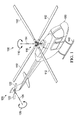
- FIG. 1 is a perspective view of a helicopter 100. Certain embodiments of the disclosure may be used with a rotary-wing aircraft such as helicopter 100. However, it should be understood that the helicopter example is given merely for illustration purposes only. Embodiments of the present disclosure are equally applicable to all airplanes, tilt-rotor aircraft, and the disclosure should not be limited to any particular setting or application.
- Helicopter 100 includes a main rotor assembly 110, a tail rotor assembly 120, a fuselage 130, and landing gear 140.
- Main rotor assembly 110 includes two or more blades 112 that are rotated about an axis of rotation 114 in either a clockwise direction or a counterclockwise direction as indicated by arrow 116.
- Main rotor assembly 110 generates a lift force that supports the weight of helicopter 100 and a thrust force that counteracts aerodynamic drag.
- Tail rotor assembly 120 includes two or more blades 122 that are rotated about an axis of rotation 124 in either a clockwise direction or a counterclockwise direction as indicated by arrow 126. Tail rotor assembly 120 counters the torque effect created by main rotor assembly 110 and allows a pilot to control the direction helicopter 100 is pointed.
- Fuselage 130 is the main body section of helicopter 100. Fuselage 130 optionally holds the crew, passengers, and/or cargo and houses the engine, transmission, gearboxes, drive shafts, control systems, etc. that are needed to establish an operable helicopter. Landing gear 140 is attached to fuselage 130, supports helicopter 100 on the ground, and allows it to take off and land.
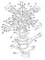
- FIG. 2 is a perspective view of a power train 200.
- Power train 200 can be used in a rotary-wing aircraft such as helicopter 100 shown in FIG. 1 .
- Power train 200 is not however limited to any particular setting.
- the particular example shown in FIG. 2 shows a soft-in plane rotor system having four blades 112.
- Embodiments of the disclosure are not limited to any particular configuration of rotor system and blades, and embodiments may include any type of rotor system (e.g., fully articulated, rigid, semi rigid, etc.) and may include any number of blades (e.g., 2, 3, 4, 5, 6, etc.).
- Power train 200 includes a transmission 202 that receives power from an engine (not shown) through a driveshaft 204.
- Transmission 202 drives accessories and controls the rotation 116 of mast 206 about an axis of rotation 114.
- Mast 206 transfers its rotational movement to blades 112 through a hub 208 that connects mast 206 to blades 112.
- Hub 208 optionally includes one or more flexible yokes 210 that enable blades 112 to flap up in the direction indicated by arrow 212 and flap down in the direction indicated by arrow 214.
- Hub 208 may also include a main rotor grip 216 for each blade 112 that is attached to hub 208.
- the main rotor grip 216 includes an outboard end that attaches to a blade 112, an inboard end that attaches to a pitch horn 218, and a spindle between the outboard end and the inboard end.
- the spindle is supported by a shear bearing 220 that holds the spindle in place and allows it to rotate.
- Shear bearing 220 is in turn held in place by a bridge plate 222 that attaches shear-bearing 220 to yoke 210.
- Each pitch horn 218 is connected to a pitch linkage 224.
- Each pitch linkage 224 is driven up and down (e.g., in the directions shown by arrows 212 and 214) by a swashplate assembly 226. Accordingly, as swashplate assembly 226 moves, it drives pitch linkage 224 which drives pitch horn 218 which rotates main rotor grip 216 about shear bearing 220. This allows the pitch of each of the blades 112 to be controlled. For instance, each blade 112 is able to rotate clockwise or counterclockwise as indicated by arrow 228 about an axis of rotation 230 that runs along the length of each blade 112.
- This disclosure provides for a yoke hub assembly comprising upper and lower portions contoured to accept a plurality of flexible yokes 210 with geometrically shaped buildups towards their inboard areas.
- a clamping force is created that may eliminate the need for these holes. Therefore, any potential failure from stresses around the bolt holes, such as interlaminar shear strain, may also be eliminated.
- Another potential benefit realized by this disclosure may be the geometrically shaped buildup areas of the composite yokes create a pivot point within the yoke hub assembly. This may in turn permit blade grip and blade to flap to a greater angle than the yoke. This kinematic effect may limit yoke strain while still providing a greater total flapping angle by the blade.
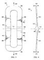
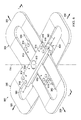
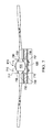
- FIGS. 3 and 4 illustrate an embodiment of a loop style 300 version of a flexible yoke 210 according to the disclosure.
- FIG. 3 depicts a top plan view of the loop style flexible yoke 300
- FIG. 4 depicts a side elevation view of the loop style flexible yoke 300.
- Loop style flexible yoke 300 provides a means of interconnecting a mast centered at an axis of rotation 114 to a plurality of blades extending in the direction of arrows 320 and 330 via a hub in a helicopter 100.
- loop style flexible yoke 300 is generally configured as an elongated loop or racetrack shape, although other shapes (rectangular, circular, oval, etc.) may be used.
- Loop style flexible yoke 300 comprises a pair of spaced apart longitudinal side portions 470 interconnected by a pair of rounded outboard portions 360 that form the elongated loop around an axis of rotation 114.
- Each longitudinal side portion 470 may comprise a central portion 340 located adjacent to the axis of rotation 114 connected to a plurality of flexure portions 350 each located outboard of the central portion 340.
- the flexure portions 350 permit a plurality of blades of a helicopter to flap in the direction of arrows 410 and 420.
- the central portion 340 of the longitudinal side portion 470 may further comprise a geometrically-shaped buildup portion 430 along a lateral axis 380 that is both orthogonal to and intersects the axis of rotation 114.
- This disclosure uses a loop style flexible yoke only as an example.
- the proposed yoke hub assembly 300 is not limited to a loop style rotor yoke, but may take the form of any flexible yoke.
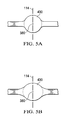
- FIG. 5A is a side view the central portion of a loop style flexible yoke 300, as seen from the line 5 - 5 in FIG. 3 .
- FIG. 5B provides an alternative embodiment to
- FIG. 5A using an oval geometrically shaped buildup portion 430 instead of a circular geometrically shaped buildup portion 430.
- Both of these views illustrate the geometrically shaped buildup portion 430 that provides a pivot point within the yoke hub assembly 500 along an orthogonal lateral axis that intersects with the axis of rotation 114. While any shape will work, there are advantages to having rounded shapes, such as ease of manufacturing and potentially increased flapping.
- FIGS. 6 and 7 illustrate an embodiment of a yoke hub assembly 600 according to the disclosure.
- FIG. 6 illustrates an isometric view of the yoke hub assembly 600
- FIG. 7 depicts a cross-section view of the yoke hub assembly 600 from the perspective of line 7 - 7 in FIG. 6 .
- Yoke hub assembly 600 comprises an upper clamping assembly 610, a lower clamping assembly 620, and a plurality of loop style flexible yokes 300.
- the upper clamping assembly 610 comprises an inboard section 612 and a plurality of arms 614 extending radially from the axis of rotation 114.
- the lower clamping assembly 620 also comprises an inboard section 612 and a plurality of arms 614 extending radially from the axis of rotation 114.
- the upper and lower clamping assembly inboard sections 612 each further comprise an aperture 613 or other attachment mechanisms that are configured to attach the yoke hub assembly 600 to the mast (not shown).
- Each of the upper clamping assembly arms 614 further comprises an outboard end 616, a top portion 717, and a bottom portion 718.
- each of the lower clamping assembly arms 614 also further comprise an outboard end 616, a top portion 717, and a bottom portion 718.
- Outboard ends 616 each have one or more apertures configured to accept nuts 710 and bolts 715 or other mechanisms to provide a clamping force between the upper and lower clamping assemblies 610 and 620.
- the bottom portions of the upper and lower clamping assemblies 718 are contoured to accept the geometrically shaped buildup portions 430 of a loop style flexible yoke 300. Additionally, to both protect and facilitate the pivoting action of the loop style flexible yoke 300, a cushioning material 730 may be included.
- the cushioning material 730 may be located between the bottom portions of the upper and lower clamping assemblies 718 and the adjacent geometrically shaped buildup areas 430 of the loop style flexible yoke 300.
- the cushioning material 730 may be any appropriate cushioning material, including elastomeric material, rubber, and polymers, such as urethane.
- the density of the cushioning material 730 may also be selected by taking into account the desired cushioning durability of the cushioning material 730.
- the cushioning material 730 may include a protective layer 740 to improve durability by mitigating frictional forces applied to the cushioning material 730 during operation.
- the protective layer 740 may comprise a cloth imbedded in the cushioning material 730.
- the protective layer 740 may comprise a fluorocarbon polymer fabric, such as Teflon cloth. The thickness of the cushioning material 730 may be selected by taking into account the desired cushioning characteristics.
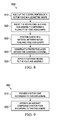
- the method 800 comprises, at block 810, building up the central portion of a rotor yoke in a geometric shape along a lateral axis that is both orthogonal to and intersects the axis of rotation.
- the built up area of the central portion of the rotor yoke provides a pivot point within the yoke assembly along the orthogonal lateral axis that intersects with the axis of rotation.
- the rotor yoke is inserted into a yoke hub assembly comprising a plurality of yoke hub clamps.
- the yoke hub clamps are contoured to fit the built up area of the center portion of the rotor yoke.
- the method 800 may optionally comprise positioning a cushioning material between the rotor yoke and the yoke hub clamps.
- the method 800 optionally comprises constructing a protective layer around the cushioning material.
- the yoke hub assembly is clamped around the rotor yoke by applying a fastening means to ensure the yoke hub assembly remains around the rotor yoke.
- FIG. 9 illustrates an exemplary method for coupling aircraft blades according to this disclosure.
- the method 900 optionally comprises, at block 910, providing a rotor yoke according to this disclosure.
- "providing” may be designing, manufacturing, or assembling the apparatus comprising a rotor yoke according to this disclosure.
- the method comprises operating an aircraft comprising a rotor yoke according to this disclosure.
- R R l + k * (R u -R l ), wherein k is a variable ranging from 1 percent to 100 percent with a 1 percent increment, e.g., k is 1 percent, 2 percent, 3 percent, 4 percent, 5 percent, ... 50 percent, 51 percent, 52 percent, ..., 95 percent, 96 percent, 97 percent, 98 percent, 99 percent, or 100 percent.
- any numerical range defined by two R numbers as defined in the above is also specifically disclosed.
Landscapes
- Engineering & Computer Science (AREA)
- Aviation & Aerospace Engineering (AREA)
- Mechanical Engineering (AREA)
- Connection Of Plates (AREA)
- Automatic Assembly (AREA)
- Structures Of Non-Positive Displacement Pumps (AREA)
- Clamps And Clips (AREA)
- Vibration Dampers (AREA)
Applications Claiming Priority (1)
| Application Number | Priority Date | Filing Date | Title |
|---|---|---|---|
| US13/797,334 US10336445B2 (en) | 2013-03-12 | 2013-03-12 | High flapping yoke hub assembly using a cylindrical elastomeric attachment to avoid holes |
Publications (3)
| Publication Number | Publication Date |
|---|---|
| EP2778055A2 true EP2778055A2 (de) | 2014-09-17 |
| EP2778055A3 EP2778055A3 (de) | 2015-04-08 |
| EP2778055B1 EP2778055B1 (de) | 2016-04-27 |
Family
ID=50000839
Family Applications (1)
| Application Number | Title | Priority Date | Filing Date |
|---|---|---|---|
| EP14152690.5A Active EP2778055B1 (de) | 2013-03-12 | 2014-01-27 | Hochschlagende Gabelnabenbaugruppe mit einer zylindrischen elastomeren Befestigung zur Vermeidung von Löchern |
Country Status (2)
| Country | Link |
|---|---|
| US (1) | US10336445B2 (de) |
| EP (1) | EP2778055B1 (de) |
Cited By (1)
| Publication number | Priority date | Publication date | Assignee | Title |
|---|---|---|---|---|
| US10086934B2 (en) | 2013-03-13 | 2018-10-02 | Bell Helicopter Textron Inc. | Composite rotor system using two race track style cantilevered yokes |
Families Citing this family (7)
| Publication number | Priority date | Publication date | Assignee | Title |
|---|---|---|---|---|
| US10577079B2 (en) | 2017-12-18 | 2020-03-03 | Bell Helicopter Textron Inc. | Dual blade fold bolts and inboard centrifugal bearing in a folding rotor blade assembly |
| US10703460B2 (en) | 2017-12-18 | 2020-07-07 | Bell Helicopter Textron Inc. | Folding spindle and bearing assembly in a folding rotor blade assembly |
| US10703469B2 (en) | 2017-12-18 | 2020-07-07 | Bell Helicopter Textron Inc. | Compact folding yoke with flexible yoke arms in a folding rotor blade assembly |
| US10640205B2 (en) | 2017-12-18 | 2020-05-05 | Bell Helicopter Textron Inc. | Outboard centrifugal force bearing with inboard blade fold axis in a folding rotor blade assembly |
| US10569869B2 (en) | 2017-12-18 | 2020-02-25 | Bell Helicopter Textron Inc. | Compact folding yoke in a folding rotor blade assembly |
| US10703461B2 (en) * | 2018-04-26 | 2020-07-07 | Bell Helicopter Textron Inc. | Blade fold method and apparatus for a tilt rotor hub |
| US10933986B2 (en) | 2018-06-22 | 2021-03-02 | Bell Helicopter Textron Inc. | Blade fold method and apparatus for a tilt rotor hub |
Family Cites Families (32)
| Publication number | Priority date | Publication date | Assignee | Title |
|---|---|---|---|---|
| US3874815A (en) | 1973-11-15 | 1975-04-01 | Boeing Co | Rotary head assembly for rotary wing aircraft |
| US4008980A (en) * | 1975-06-26 | 1977-02-22 | United Technologies Corporation | Composite helicopter spar and means to alleviate stress concentration |
| US4047839A (en) * | 1976-05-28 | 1977-09-13 | United Technologies Corporation | Torque reacting means for the hubs of cross beam rotors |
| FR2397325A1 (fr) | 1977-07-13 | 1979-02-09 | Aerospatiale | Moyeu de rotor, en particulier pour le rotor principal d'un helicoptere |
| US4227857A (en) * | 1977-08-19 | 1980-10-14 | Textron, Inc. | Composite flexural yoke for helicopters |
| US4293276A (en) | 1978-10-27 | 1981-10-06 | Textron Inc. | Laminated composite rotor yoke |
| US4430045A (en) | 1979-04-24 | 1984-02-07 | Bell Helicopter Textron, Inc. | Helicopter power train for distributing rotor blade flapping displacements through a plurality of drive train components |
| US4349316A (en) | 1979-04-24 | 1982-09-14 | Textron, Inc. | Twist control for helicopter tail rotor pitch change |
| DE2929906C3 (de) * | 1979-07-24 | 1982-01-21 | Messerschmitt-Bölkow-Blohm GmbH, 8000 München | Rotor für einen Hubschrauber mit zumindest einem Paar einander gegenüberliegender Rotorblätter |
| US4349317A (en) | 1979-11-02 | 1982-09-14 | The Boeing Company | Bearingless rotor for single and tandem helicopters |
| US4381902A (en) * | 1979-12-20 | 1983-05-03 | Hughes Helicopters, Inc. | Helicopter tail rotor of the elastomerically-mounted composite flexbeam type |
| US4427340A (en) | 1982-06-24 | 1984-01-24 | Bell Helicopter Textron Inc. | Soft inplane bearingless helicopter rotor |
| FR2542695B1 (fr) | 1983-03-18 | 1985-07-26 | Aerospatiale | Helice multipale a pas variable a pale s en materiaux composites demontables individuellement, procede de fabrication de telles pales et pales ainsi realisees |
| US4650401A (en) | 1983-04-07 | 1987-03-17 | Mcdonnell Douglas Helicopter Company | Flat strap cruciform flexure for helicopter rotor systems |
| US4676720A (en) | 1984-07-10 | 1987-06-30 | Kawasaki Jukogyo Kabushiki Kaisha | Bearingless hub structure for rotary-wing aircrafts |
| US4708591A (en) * | 1986-01-15 | 1987-11-24 | Stephan Roman | Bladed aircraft rotor with flexible blade mountings |
| US4746272A (en) * | 1986-07-23 | 1988-05-24 | United Technologies Corporation | Lobed composite flexbeam |
| US4898515A (en) | 1986-07-23 | 1990-02-06 | United Technologies Corporation | External wrap of composite flexbeam |
| JP2583259B2 (ja) | 1988-01-08 | 1997-02-19 | 富士重工業株式会社 | ヘリコプタ用フレックスビーム |
| US4923276A (en) | 1989-02-13 | 1990-05-08 | Teledyne Industries, Inc. | Tapered optical fiber telescope, tracking system apparatus and method incorporating tapered optical fiber telescopes |
| CA2042532C (en) | 1990-05-30 | 2002-03-12 | Francis E. Byrnes | Spar-to-hub joint for a flexbeam helicopter rotor |
| US5690474A (en) | 1996-07-18 | 1997-11-25 | Sikorsky Aircraft Corporation | Optimized composite flexbeam for helicopter tail rotors |
| FR2778165B1 (fr) * | 1998-04-29 | 2000-07-13 | Eurocopter France | Rotor sans articulation avec demi-paliers precomprimes d'appui des manchettes de pied de pale sur des lames torsibles d'emplanture des pales |
| ITMI991124A1 (it) | 1998-05-28 | 2000-11-21 | Eurocopter Deutschland | Pala per un rotore privo di supporto di un elicottero |
| US7665969B2 (en) * | 2005-01-24 | 2010-02-23 | Bell Helicopter Textron Inc. | Assembly for providing flexure to blade system |
| WO2007106064A2 (en) | 2006-02-24 | 2007-09-20 | Bell Helicopter Textron, Inc. | Helicopter rotor yoke and method of making same |
| EP2240366B1 (de) | 2008-02-12 | 2014-06-18 | Bell Helicopter Textron Inc. | Schwenkdämpfer für rotornaben |
| EP2387531B1 (de) | 2009-01-19 | 2015-11-04 | Bell Helicopter Textron Inc. | Konfiguration eines steifen rotors |
| US9073625B1 (en) * | 2010-02-11 | 2015-07-07 | Textron Innovations Inc. | Helicopter rotor yoke |
| EP2686239B1 (de) | 2011-06-29 | 2015-08-12 | Bell Helicopter Textron Inc. | Rotornabe für schaufeln mit hohem trägheitsmoment |
| US8926281B2 (en) | 2012-02-21 | 2015-01-06 | Textron Innovations Inc. | Compact rotorcraft dual-element spherical elastomeric centrifugal-force bearing assembly |
| US9505489B2 (en) | 2013-03-13 | 2016-11-29 | Bell Helicopter Textron Inc. | Flexing clevis arrangement bolted joint attachment for flexible rotor hub with high offset and high flapping |
-
2013
- 2013-03-12 US US13/797,334 patent/US10336445B2/en active Active
-
2014
- 2014-01-27 EP EP14152690.5A patent/EP2778055B1/de active Active
Non-Patent Citations (1)
| Title |
|---|
| None |
Cited By (2)
| Publication number | Priority date | Publication date | Assignee | Title |
|---|---|---|---|---|
| US10086934B2 (en) | 2013-03-13 | 2018-10-02 | Bell Helicopter Textron Inc. | Composite rotor system using two race track style cantilevered yokes |
| US10569867B2 (en) | 2013-03-13 | 2020-02-25 | Bell Helicopter Textron Inc. | Composite rotor system using two race track style cantilevered yokes |
Also Published As
| Publication number | Publication date |
|---|---|
| US10336445B2 (en) | 2019-07-02 |
| EP2778055A3 (de) | 2015-04-08 |
| EP2778055B1 (de) | 2016-04-27 |
| US20140271199A1 (en) | 2014-09-18 |
Similar Documents
| Publication | Publication Date | Title |
|---|---|---|
| US10336445B2 (en) | High flapping yoke hub assembly using a cylindrical elastomeric attachment to avoid holes | |
| US10384771B2 (en) | Gimbaled tail rotor hub with spherical elastomeric centrifugal force bearing for blade retention and pitch change articulation | |
| CA2802389C (en) | Method and apparatus for in-flight blade folding | |
| EP2832640B1 (de) | Flexur aus Verbundwerkstoff für Kipprotor-Rotorsystem | |
| EP2778051B1 (de) | Rotor Systerm weich in Rotorebene uns steif ausserhalb der Rotorebene | |
| EP3333074B1 (de) | Soft-in-plane proprotorsysteme | |
| EP2570346A1 (de) | Rotor mit Schaufeln mit Außenschaufelverkleidung und Innenstrukturelement | |
| US9476312B2 (en) | Swashplateless active blade pitch control with a mechanical delta-3 restraint having an instantaneous blade pitch-flap coupling response | |
| EP2657130B1 (de) | Flugzeugrotor mit diskreten Schlaggelenken | |
| US9657816B2 (en) | Drive link for tiltrotor rotor system | |
| CN108069030B (zh) | 用于倾转旋翼飞行器的推进旋翼系统 | |
| US10023294B2 (en) | Tail spar spring | |
| CA2845844C (en) | Low shear modulus transition shim for elastomeric bearing bonding in torsional applications | |
| US9701403B2 (en) | Broad goods composite yoke for rotor system | |
| EP2778053A1 (de) | Faserausrichtung zur Erméglichung einer automatisierten Lagenverlegung von Verbundstoff-Rotorjochen | |
| EP3575211A1 (de) | Rotoranordnung mit blättern mit hoher lockzahl | |
| EP3072814B1 (de) | Heckrotorblattanordung eines drehflueglers und ihr herstellungsverfahren | |
| EP3385161B1 (de) | Wippendes heckrotorjoch |
Legal Events
| Date | Code | Title | Description |
|---|---|---|---|
| PUAI | Public reference made under article 153(3) epc to a published international application that has entered the european phase |
Free format text: ORIGINAL CODE: 0009012 |
|
| 17P | Request for examination filed |
Effective date: 20140127 |
|
| AK | Designated contracting states |
Kind code of ref document: A2 Designated state(s): AL AT BE BG CH CY CZ DE DK EE ES FI FR GB GR HR HU IE IS IT LI LT LU LV MC MK MT NL NO PL PT RO RS SE SI SK SM TR |
|
| AX | Request for extension of the european patent |
Extension state: BA ME |
|
| RIC1 | Information provided on ipc code assigned before grant |
Ipc: B64C 27/33 20060101AFI20141002BHEP |
|
| PUAL | Search report despatched |
Free format text: ORIGINAL CODE: 0009013 |
|
| AK | Designated contracting states |
Kind code of ref document: A3 Designated state(s): AL AT BE BG CH CY CZ DE DK EE ES FI FR GB GR HR HU IE IS IT LI LT LU LV MC MK MT NL NO PL PT RO RS SE SI SK SM TR |
|
| AX | Request for extension of the european patent |
Extension state: BA ME |
|
| RIC1 | Information provided on ipc code assigned before grant |
Ipc: B64C 27/33 20060101AFI20150227BHEP |
|
| 17Q | First examination report despatched |
Effective date: 20150318 |
|
| GRAP | Despatch of communication of intention to grant a patent |
Free format text: ORIGINAL CODE: EPIDOSNIGR1 |
|
| INTG | Intention to grant announced |
Effective date: 20151117 |
|
| GRAS | Grant fee paid |
Free format text: ORIGINAL CODE: EPIDOSNIGR3 |
|
| GRAA | (expected) grant |
Free format text: ORIGINAL CODE: 0009210 |
|
| AK | Designated contracting states |
Kind code of ref document: B1 Designated state(s): AL AT BE BG CH CY CZ DE DK EE ES FI FR GB GR HR HU IE IS IT LI LT LU LV MC MK MT NL NO PL PT RO RS SE SI SK SM TR |
|
| REG | Reference to a national code |
Ref country code: GB Ref legal event code: FG4D |
|
| REG | Reference to a national code |
Ref country code: CH Ref legal event code: EP |
|
| REG | Reference to a national code |
Ref country code: AT Ref legal event code: REF Ref document number: 794465 Country of ref document: AT Kind code of ref document: T Effective date: 20160515 |
|
| REG | Reference to a national code |
Ref country code: IE Ref legal event code: FG4D |
|
| REG | Reference to a national code |
Ref country code: DE Ref legal event code: R096 Ref document number: 602014001606 Country of ref document: DE |
|
| REG | Reference to a national code |
Ref country code: LT Ref legal event code: MG4D |
|
| REG | Reference to a national code |
Ref country code: NL Ref legal event code: MP Effective date: 20160427 |
|
| REG | Reference to a national code |
Ref country code: AT Ref legal event code: MK05 Ref document number: 794465 Country of ref document: AT Kind code of ref document: T Effective date: 20160427 |
|
| PG25 | Lapsed in a contracting state [announced via postgrant information from national office to epo] |
Ref country code: NL Free format text: LAPSE BECAUSE OF FAILURE TO SUBMIT A TRANSLATION OF THE DESCRIPTION OR TO PAY THE FEE WITHIN THE PRESCRIBED TIME-LIMIT Effective date: 20160427 |
|
| PG25 | Lapsed in a contracting state [announced via postgrant information from national office to epo] |
Ref country code: LT Free format text: LAPSE BECAUSE OF FAILURE TO SUBMIT A TRANSLATION OF THE DESCRIPTION OR TO PAY THE FEE WITHIN THE PRESCRIBED TIME-LIMIT Effective date: 20160427 Ref country code: NO Free format text: LAPSE BECAUSE OF FAILURE TO SUBMIT A TRANSLATION OF THE DESCRIPTION OR TO PAY THE FEE WITHIN THE PRESCRIBED TIME-LIMIT Effective date: 20160727 Ref country code: PL Free format text: LAPSE BECAUSE OF FAILURE TO SUBMIT A TRANSLATION OF THE DESCRIPTION OR TO PAY THE FEE WITHIN THE PRESCRIBED TIME-LIMIT Effective date: 20160427 Ref country code: FI Free format text: LAPSE BECAUSE OF FAILURE TO SUBMIT A TRANSLATION OF THE DESCRIPTION OR TO PAY THE FEE WITHIN THE PRESCRIBED TIME-LIMIT Effective date: 20160427 |
|
| PG25 | Lapsed in a contracting state [announced via postgrant information from national office to epo] |
Ref country code: SE Free format text: LAPSE BECAUSE OF FAILURE TO SUBMIT A TRANSLATION OF THE DESCRIPTION OR TO PAY THE FEE WITHIN THE PRESCRIBED TIME-LIMIT Effective date: 20160427 Ref country code: PT Free format text: LAPSE BECAUSE OF FAILURE TO SUBMIT A TRANSLATION OF THE DESCRIPTION OR TO PAY THE FEE WITHIN THE PRESCRIBED TIME-LIMIT Effective date: 20160829 Ref country code: AT Free format text: LAPSE BECAUSE OF FAILURE TO SUBMIT A TRANSLATION OF THE DESCRIPTION OR TO PAY THE FEE WITHIN THE PRESCRIBED TIME-LIMIT Effective date: 20160427 Ref country code: GR Free format text: LAPSE BECAUSE OF FAILURE TO SUBMIT A TRANSLATION OF THE DESCRIPTION OR TO PAY THE FEE WITHIN THE PRESCRIBED TIME-LIMIT Effective date: 20160728 Ref country code: ES Free format text: LAPSE BECAUSE OF FAILURE TO SUBMIT A TRANSLATION OF THE DESCRIPTION OR TO PAY THE FEE WITHIN THE PRESCRIBED TIME-LIMIT Effective date: 20160427 Ref country code: HR Free format text: LAPSE BECAUSE OF FAILURE TO SUBMIT A TRANSLATION OF THE DESCRIPTION OR TO PAY THE FEE WITHIN THE PRESCRIBED TIME-LIMIT Effective date: 20160427 Ref country code: RS Free format text: LAPSE BECAUSE OF FAILURE TO SUBMIT A TRANSLATION OF THE DESCRIPTION OR TO PAY THE FEE WITHIN THE PRESCRIBED TIME-LIMIT Effective date: 20160427 Ref country code: LV Free format text: LAPSE BECAUSE OF FAILURE TO SUBMIT A TRANSLATION OF THE DESCRIPTION OR TO PAY THE FEE WITHIN THE PRESCRIBED TIME-LIMIT Effective date: 20160427 |
|
| PG25 | Lapsed in a contracting state [announced via postgrant information from national office to epo] |
Ref country code: BE Free format text: LAPSE BECAUSE OF FAILURE TO SUBMIT A TRANSLATION OF THE DESCRIPTION OR TO PAY THE FEE WITHIN THE PRESCRIBED TIME-LIMIT Effective date: 20160427 |
|
| REG | Reference to a national code |
Ref country code: FR Ref legal event code: PLFP Year of fee payment: 4 |
|
| REG | Reference to a national code |
Ref country code: DE Ref legal event code: R097 Ref document number: 602014001606 Country of ref document: DE |
|
| PG25 | Lapsed in a contracting state [announced via postgrant information from national office to epo] |
Ref country code: SK Free format text: LAPSE BECAUSE OF FAILURE TO SUBMIT A TRANSLATION OF THE DESCRIPTION OR TO PAY THE FEE WITHIN THE PRESCRIBED TIME-LIMIT Effective date: 20160427 Ref country code: EE Free format text: LAPSE BECAUSE OF FAILURE TO SUBMIT A TRANSLATION OF THE DESCRIPTION OR TO PAY THE FEE WITHIN THE PRESCRIBED TIME-LIMIT Effective date: 20160427 Ref country code: DK Free format text: LAPSE BECAUSE OF FAILURE TO SUBMIT A TRANSLATION OF THE DESCRIPTION OR TO PAY THE FEE WITHIN THE PRESCRIBED TIME-LIMIT Effective date: 20160427 Ref country code: RO Free format text: LAPSE BECAUSE OF FAILURE TO SUBMIT A TRANSLATION OF THE DESCRIPTION OR TO PAY THE FEE WITHIN THE PRESCRIBED TIME-LIMIT Effective date: 20160427 Ref country code: CZ Free format text: LAPSE BECAUSE OF FAILURE TO SUBMIT A TRANSLATION OF THE DESCRIPTION OR TO PAY THE FEE WITHIN THE PRESCRIBED TIME-LIMIT Effective date: 20160427 |
|
| PG25 | Lapsed in a contracting state [announced via postgrant information from national office to epo] |
Ref country code: SM Free format text: LAPSE BECAUSE OF FAILURE TO SUBMIT A TRANSLATION OF THE DESCRIPTION OR TO PAY THE FEE WITHIN THE PRESCRIBED TIME-LIMIT Effective date: 20160427 |
|
| PLBE | No opposition filed within time limit |
Free format text: ORIGINAL CODE: 0009261 |
|
| STAA | Information on the status of an ep patent application or granted ep patent |
Free format text: STATUS: NO OPPOSITION FILED WITHIN TIME LIMIT |
|
| 26N | No opposition filed |
Effective date: 20170130 |
|
| PG25 | Lapsed in a contracting state [announced via postgrant information from national office to epo] |
Ref country code: SI Free format text: LAPSE BECAUSE OF FAILURE TO SUBMIT A TRANSLATION OF THE DESCRIPTION OR TO PAY THE FEE WITHIN THE PRESCRIBED TIME-LIMIT Effective date: 20160427 |
|
| REG | Reference to a national code |
Ref country code: CH Ref legal event code: PL |
|
| PG25 | Lapsed in a contracting state [announced via postgrant information from national office to epo] |
Ref country code: MC Free format text: LAPSE BECAUSE OF FAILURE TO SUBMIT A TRANSLATION OF THE DESCRIPTION OR TO PAY THE FEE WITHIN THE PRESCRIBED TIME-LIMIT Effective date: 20160427 |
|
| PG25 | Lapsed in a contracting state [announced via postgrant information from national office to epo] |
Ref country code: LI Free format text: LAPSE BECAUSE OF NON-PAYMENT OF DUE FEES Effective date: 20170131 Ref country code: CH Free format text: LAPSE BECAUSE OF NON-PAYMENT OF DUE FEES Effective date: 20170131 |
|
| REG | Reference to a national code |
Ref country code: IE Ref legal event code: MM4A |
|
| PG25 | Lapsed in a contracting state [announced via postgrant information from national office to epo] |
Ref country code: LU Free format text: LAPSE BECAUSE OF NON-PAYMENT OF DUE FEES Effective date: 20170127 |
|
| REG | Reference to a national code |
Ref country code: FR Ref legal event code: PLFP Year of fee payment: 5 |
|
| PG25 | Lapsed in a contracting state [announced via postgrant information from national office to epo] |
Ref country code: IE Free format text: LAPSE BECAUSE OF NON-PAYMENT OF DUE FEES Effective date: 20170127 |
|
| PG25 | Lapsed in a contracting state [announced via postgrant information from national office to epo] |
Ref country code: MT Free format text: LAPSE BECAUSE OF NON-PAYMENT OF DUE FEES Effective date: 20170127 |
|
| PG25 | Lapsed in a contracting state [announced via postgrant information from national office to epo] |
Ref country code: AL Free format text: LAPSE BECAUSE OF FAILURE TO SUBMIT A TRANSLATION OF THE DESCRIPTION OR TO PAY THE FEE WITHIN THE PRESCRIBED TIME-LIMIT Effective date: 20160427 |
|
| PG25 | Lapsed in a contracting state [announced via postgrant information from national office to epo] |
Ref country code: HU Free format text: LAPSE BECAUSE OF FAILURE TO SUBMIT A TRANSLATION OF THE DESCRIPTION OR TO PAY THE FEE WITHIN THE PRESCRIBED TIME-LIMIT; INVALID AB INITIO Effective date: 20140127 |
|
| PG25 | Lapsed in a contracting state [announced via postgrant information from national office to epo] |
Ref country code: BG Free format text: LAPSE BECAUSE OF FAILURE TO SUBMIT A TRANSLATION OF THE DESCRIPTION OR TO PAY THE FEE WITHIN THE PRESCRIBED TIME-LIMIT Effective date: 20160427 |
|
| PG25 | Lapsed in a contracting state [announced via postgrant information from national office to epo] |
Ref country code: CY Free format text: LAPSE BECAUSE OF NON-PAYMENT OF DUE FEES Effective date: 20160427 |
|
| PG25 | Lapsed in a contracting state [announced via postgrant information from national office to epo] |
Ref country code: MK Free format text: LAPSE BECAUSE OF FAILURE TO SUBMIT A TRANSLATION OF THE DESCRIPTION OR TO PAY THE FEE WITHIN THE PRESCRIBED TIME-LIMIT Effective date: 20160427 |
|
| PG25 | Lapsed in a contracting state [announced via postgrant information from national office to epo] |
Ref country code: TR Free format text: LAPSE BECAUSE OF FAILURE TO SUBMIT A TRANSLATION OF THE DESCRIPTION OR TO PAY THE FEE WITHIN THE PRESCRIBED TIME-LIMIT Effective date: 20160427 |
|
| PG25 | Lapsed in a contracting state [announced via postgrant information from national office to epo] |
Ref country code: IS Free format text: LAPSE BECAUSE OF FAILURE TO SUBMIT A TRANSLATION OF THE DESCRIPTION OR TO PAY THE FEE WITHIN THE PRESCRIBED TIME-LIMIT Effective date: 20160827 |
|
| P01 | Opt-out of the competence of the unified patent court (upc) registered |
Effective date: 20230602 |
|
| PGFP | Annual fee paid to national office [announced via postgrant information from national office to epo] |
Ref country code: GB Payment date: 20260127 Year of fee payment: 13 |
|
| PGFP | Annual fee paid to national office [announced via postgrant information from national office to epo] |
Ref country code: DE Payment date: 20260128 Year of fee payment: 13 |
|
| PGFP | Annual fee paid to national office [announced via postgrant information from national office to epo] |
Ref country code: IT Payment date: 20260121 Year of fee payment: 13 |
|
| PGFP | Annual fee paid to national office [announced via postgrant information from national office to epo] |
Ref country code: FR Payment date: 20260126 Year of fee payment: 13 |