EP2778281B1 - Échangeur de chaleur pour condensation dans le séchage de vêtements et système de séchage de vêtements et dispositif de séchage de vêtements - Google Patents
Échangeur de chaleur pour condensation dans le séchage de vêtements et système de séchage de vêtements et dispositif de séchage de vêtements Download PDFInfo
- Publication number
- EP2778281B1 EP2778281B1 EP12847897.1A EP12847897A EP2778281B1 EP 2778281 B1 EP2778281 B1 EP 2778281B1 EP 12847897 A EP12847897 A EP 12847897A EP 2778281 B1 EP2778281 B1 EP 2778281B1
- Authority
- EP
- European Patent Office
- Prior art keywords
- air
- heat exchanger
- air channel
- heat recovery
- clothes
- Prior art date
- Legal status (The legal status is an assumption and is not a legal conclusion. Google has not performed a legal analysis and makes no representation as to the accuracy of the status listed.)
- Active
Links
Images


Classifications
-
- D—TEXTILES; PAPER
- D06—TREATMENT OF TEXTILES OR THE LIKE; LAUNDERING; FLEXIBLE MATERIALS NOT OTHERWISE PROVIDED FOR
- D06F—LAUNDERING, DRYING, IRONING, PRESSING OR FOLDING TEXTILE ARTICLES
- D06F58/00—Domestic laundry dryers
- D06F58/20—General details of domestic laundry dryers
- D06F58/22—Lint collecting arrangements
-
- D—TEXTILES; PAPER
- D06—TREATMENT OF TEXTILES OR THE LIKE; LAUNDERING; FLEXIBLE MATERIALS NOT OTHERWISE PROVIDED FOR
- D06F—LAUNDERING, DRYING, IRONING, PRESSING OR FOLDING TEXTILE ARTICLES
- D06F58/00—Domestic laundry dryers
- D06F58/20—General details of domestic laundry dryers
- D06F58/24—Condensing arrangements
-
- F—MECHANICAL ENGINEERING; LIGHTING; HEATING; WEAPONS; BLASTING
- F26—DRYING
- F26B—DRYING SOLID MATERIALS OR OBJECTS BY REMOVING LIQUID THEREFROM
- F26B21/00—Arrangements for supplying or controlling air or other gases for drying solid materials or objects
- F26B21/30—Controlling, e.g. regulating, parameters of gas supply
- F26B21/33—Humidity
- F26B21/333—Humidity by condensing the moisture in the drying medium, which may be recycled, e.g. using a heat pump cycle
-
- D—TEXTILES; PAPER
- D06—TREATMENT OF TEXTILES OR THE LIKE; LAUNDERING; FLEXIBLE MATERIALS NOT OTHERWISE PROVIDED FOR
- D06F—LAUNDERING, DRYING, IRONING, PRESSING OR FOLDING TEXTILE ARTICLES
- D06F58/00—Domestic laundry dryers
- D06F58/20—General details of domestic laundry dryers
- D06F58/206—Heat pump arrangements
Definitions
- the invention relates to a heat exchanger for condensation in clothes drying as defined by the preamble portion of claim 1. Further, the invention relates to a clothes dryer and clothes drying system including such a heat exchanger.
- the apparatus for producing hot air almost adopts the way of heating air by heater.
- the existing electro-thermal clothes dryer usually takes the heating strip/pipe as the heat source.
- This kind of product has high energy consumption, long drying time and poor security.
- heat pump clothes dryer which employs heat pump system, is developed. This kind of clothes dryer strengthens the cyclic utilization of heat, improves the utilization efficiency of heat and lowers the power consumption.
- the heat pump type clothes dryer apparatus are provided with the following air circulation channels: the air heated by the condenser in heat pump circulation system is sent into the drying chamber filling with clothes, and the air after absorbing moisture of clothes is then sent back to the evaporator for desiccation, after that, the air is again heated by the condenser and sent to the drying chamber.
- the energy consumption of the heat pump type clothes dryer has decreased, the drying speed is not improved, the time required for drying process is still long. It usually takes 2 to 3 hours to dry 7-8KG clothes.
- people have taken various ways to achieve this purpose.
- the way that the clothes dryer adopted is to elevate temperature, enhance the ventilation of surface, and increase the heat-exchange surface. Although these ways have been used, the energy consumption and drying time are still high in the drying process. And if it proceeds to drying clothes under the high temperature, the fabric can be damaged, and may be prone to wrinkle and shrink.
- Chinese patent document CN1936160B discloses a clothes drying apparatus in which the heat pump generating the drying air circulating between the drying chamber and the heat pump achieves stable operation.
- the air heated by the heater in heat pump is sent into the bucket which serves as drying chamber, and then the air emitted from the bucket returns back to the heat pump through the filter unit, and sent to the heater after being dehumidified by the heat absorber as a result of forming an air circulation channels.
- the filter unit is provided with a lint flushing filter and pipelines communicating with air outlet and air inlet.
- the drying circulatory system of the existing clothes dryer utilizes the condensing heat exchanger equipped with cold air as the cooling medium, which is applied to clothes dryer or integral washing-drying machine.
- the one is to utilize the outside cool air to convert the hot and humid air generated in drying process into hypothermal and low-humidity air and recycle it; the other one is to exchange the hot and humid air generated in drying process with the outside hypothermal and low-humidity air and exhaust it, and then send the preheated outside air after exchanging inside for recycling.
- These patterns have their disadvantages.
- As for the former one a large amount of outside cooling air is needed, and a relatively large quality of heat is taken away, thus the air reentering in the drying circulation needs to be heated with much energy.
- the moisture in the moist air cannot be condensed totally, and there's still plenty of moisture access to the environment and influence the comfort level of the environment.
- the drying fan drives the drying air to flow along with the drying route, heating strip/pipe starts to heat, the hot air enters into the washing tub/clothes drying tub, in which the temperature of the clothes and moisture rises.
- the moisture evaporates into water vapor and then enters into the condensing heat exchanger by lint flushing filter.
- the condensate fan drives the outside air to exchange heat with the internal air.
- the internal hot and humid air cools down, the water vapor condenses into liquid water, and the hot and humid air transforms into dry and hypothermal air which then is sent to heat strip/pipe by drying fan for being heated and drying circularly clothes.
- the aforesaid condensing heat exchanger is made of the sheet metals, which are formed the drying wind channels and interlaced condensing wind channels by welding procedure.
- Such processing technology of condenser is quite complicated and the condenser cannot be processed and manufactured according to washing machine structure arbitrarily, and it costs high.
- a heat exchanger for condensation in clothes drying according to the preamble portion of claim 1 is known from EP 2 169 107 A1 .
- a spraying device is arranged at an outlet of the heat exchanger for spraying water towards the heat exchanger to thereby flush lint.
- the invention aims at providing a simple-structured and low-cost heat exchanger for condensation in clothes drying.
- the invention provides a clothes drying system and clothes dryer with the heat exchanger.
- the condensed dry air is preheated by the residual heat of the hot and humid air exchanging heat with clothes, and then is heated, so as to raise the clothes drying efficiency, save electric energy and time.
- the heat exchanger and drying system of this invention may also be applied to an integral washing-drying machine.
- the heat exchanger may be made of plastic film, a non-metallic material, with a thickness of 0.05 ⁇ 1.5mm. Compared with metallic heat-exchanger, the exchanger of the invention has lower production cost while higher heat exchanger efficiency. Besides, plastic film, as the material of heat exchanger, is easier to be manufactured and assembled in accordance with the various dying power of clothes dryers or integral washing-drying machines. Moreover, clothes dryers or integral washing-drying machines with the heat exchanger are much lighter, which is more convenient and cost-saving for transportation.
- the drying system and clothes dryer of the invention comprise the heat exchanger, the water collection box and the residual heat recovery device which comprises two air channels, namely, the hot and humid air channel and the residual heat recovery air channel.
- the residual heat recovery air channel air condensed through the heat exchanger pre-cools the hot and humid air in the hot and humid air channel from the clothes tub of the clothes dryer. Meanwhile, it also get preheated while absorbing the heat, thus lowering the energy loss of heating the heater of the clothes dry to the drying temperature, enhancing the drying efficiency and saving power.
- precooling function of the residual heat recovery device can also reduce the flow of condensed air outside and the noise of condensate fan.
- the heat exchanger for condensation in clothes drying is installed in a clothes dryer or washing machine having the function of drying.
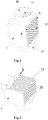
- the heat exchanger 1 made of plastic film, is an external air-cooled heat exchanger.
- the interior of the heat exchanger comprises two groups of air channels going towards different directions and not communicating with each other, which are respectively a condensing air channel 11 and an external air channel 12.
- Each group of air channel is composed of a plurality of air chambers.
- the air chambers of two groups of air channels are arranged alternately in turn.
- the space between neighboring air chambers of the same group of air channel is an air chamber of the other group of air channel, and all of them are made of interval plastic film walls.
- a condensate fan 15 (see Figures 5 and 6 ) is set on one end of the external air channel 12, and the other end directly leads to the outside.
- the hot and humid air is put in through one end of the condensing air channel 11, and the condensed air and water are exhausted through the other end.
- the condensing air channel 11 is composed of air chambers 13.
- the external air channel 12 is composed of air chambers 14.
- the space between neighboring air chambers 13 of the condensing air channel 11 is an air chamber 14 of the external air channel 12.
- the thickness L of the plastic film is in the range of 0.05mm to 1.5mm; preferably, the thickness of the plastic film is in the rang of 0.08mm to 0.8mm; more preferably, the thickness of the plastic film is in the rang of 0.1mm to 0.5mm.
- the embodiment adopts the plastic film with the thickness of 0.1mm.
- the shape of the cross-section of the air chamber is not limited to rectangular, circle or elliptic type. Various corrugated shape for the drop of condensate water can also be set on the wall of the air chamber, or combination of the aforesaid shapes.
- the plastic film of the present invention has heat resistance, for example, polyimide film, which is undistorted even at a temperature of 150°C.
- the plastic film in the embodiment is polyethylene film with a distortion temperature of 80-100°C.
- a mechanism for flushing lint is comprised.
- the mechanism for flushing lint is arranged at one end of a hot and humid air inlet 16 of the condensing air channel 11 of the heat exchanger 1.
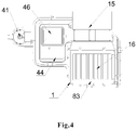
- the mechanism for flushing lint included a flushing valve connection 82 communicated with the exterior, a flushing passageway 83 communicating to the flushing valve connection and being set annularly along the air inlet for the hot and humid air of the heat exchanger, and a flushing mouth 81 set along the edge of the flushing passageway for flushing water towards the air channel for the hot and humid air in the inside of the heat exchanger.
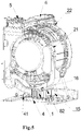
- the foregoing heat exchanger may be installed inside a integral washing-drying machine (see Figure 5 ) or a clothes dryer (see Figure 7 ), which comprises a clothes tub 2, an air outlet 21, a filter 3, a heat exchanger 1, a water collection box 4, a drying fan 5, a heating unit 6 and an air inlet 22.
- the air outlet 21 communicates with the heat exchanger 1 which communicates with the water collection box 4; and the water collection box 4 communicates with the air inlet 22.
- the filter 3 is arranged between the air outlet 22 and the heat exchanger 1, and the drying fan 5 and the heating unit 6 are arranged between the water collection box 4 and air inlet 22 in turn.
- the water collection box 4 communicates with the outside through a draining pump 41, and a water level inductive switch 42 for controlling to turn on the draining pump 41 is installed in the water collection box 4.
- the water collection box 4 comprises a water-holding box 43 and a top cover 44 (see Figures 3 and 4 ).
- An inlet 45 communicating with a hot and humid air outlet 17 of the condensing air channel of the heat exchanger and an outlet 46 communicating with the air inlet 22 of the clothes dryer are arranged on the top cover 44.
- the clothes tub 2, the air outlet 21, the filter 3, the drying fan 5, the heat unit 6 and the air inlet 22 all may adopt the designs in prior arts.
- the air inlet and the air outlet are both the air inlet and the air outlet of the clothes tub.
- the heating unit 6 is generally made of heating pipe or heater strip or heating plate.
- the filter 3 is composed of at least one layer of filter net, which is dismountable.
- the hot and humid air from the air outlet of the clothes tub 2 enters the condensing air channel 11 of the heat exchange 1 along the pipeline.
- the external air passed in through the external air channel 12 of the heat exchanger 1 exchanges heat with the hot and humid air in the condensing air channel 11.
- Temperature of the hot and humid air in condensing air channel 11 drops while its relative humidity rises.
- Partial air around the wall of the air chambers gets saturated, and vapors in the air precipitate and flow into the water collection box 4 along with the wall of the air chambers.
- the draining pump 41 is turned on, discharging the condensate water.
- the condensed low-heat and low-humidity air passes through the water collection box 4, and is sent to the heating unit 6 for heating by the drying fan 5, and then reflows into the clothes tub 2 through the air inlet.
- the drying system of this embodiment consists of the heat exchanger 1 of Embodiment 1 or 2 and a residual heat recovery device 7.
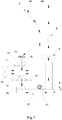
- the interior of the residual heat recovery device 7 comprises two groups of air channels, namely, a hot and humid air channel 71 and a residual heat recovery air channel 72.
- the two groups of air channels form a heat exchange structure.
- the hot and humid air channel 71 communicates with the condensing air channel 11, the water collection box 4 and the residual heat recovery air channel 72 in turn through ventilating ducts.
- the residual heat recovery device 7 comprises a shell 70, and a heat exchanger 73 arranged inside the shell.
- the hot and humid air channel 71 and the residual heat recovery air channel 72 are arranged in the heat exchanger 73 in the way of bidirectional cross convection.
- an air inlet 74 of the hot and humid air channel and an air outlet 75 of the residual heat recovery air channel are arranged on the upper of the shell 70, and an air outlet 76 of the hot and humid air channel and an air inlet 77 of the residual heat recovery air channel are arranged on the lower of the shell 70.
- the air inlet 74 and the outlet 76 of the hot air and humid air channel all are arranged on the cross.
- the air outlet 76 of the hot and humid air channel of the residual heat recovery device 7 communicates with the air inlet 16 of the hot and humid air channel of the condensing air channel 11 of the heat exchanger 1, and the air inlet 77 of the residual heat recovery air channel communicates with the outlet 46 of the water collection box 4.
- two groups of heat exchange fins form the hot and humid air channel and the residual heat recovery air channel.
- Each group of the heat exchange fins form a plurality of air channels along the same direction.
- the space between the neighboring air channels of the same group is an air channel of the other group.
- the air channels composed of two groups of heat exchange fins are set by interval, which forms the heat exchange structure with bidirectional cross convection.
- the interior of the heat exchanger 73 is composed of multiple parallel plates. Air channels 78 and 79 are arranged between two adjacent plates. Two group of isolated and crossed air channels are formed by blocking the air channels at intervals along the inlet direction and the outlet direction. Alternatively, in an integral structure, penetrating two groups of two-way crossed air channels 78 and 79. Or the heat exchanger 73 can also adopt the existing plate-interval recuperative heat exchanger.
- the difference from that of Embodiment 3 is that the clothes dryer or the washing-drying machine of the embodiment is arranged the residual heat recovery device 7 on the basis of Embodiment 4.
- the residual heat recovery device 7 is set between the filter 3 and the heat exchanger 1, also between the water collection box 4 and the drying fan 5.
- the hot and humid air channel 71 communicates with the filter 3 and the heat exchanger 1
- the residual heat recovery air channel 72 communicates with the water collection box 4 and the drying fan 5.
- the hot and humid air passes out from the air outlet of the clothes tub 2, and flows through the hot and humid air channel 71 of the residual heat recovery device 7, the heat exchanger 1 and the water collection box 4 successively, then flows through the residual heat recovery air channel 72 of the residual heat recovery device 7.
- it is completed to recover the residual heat.
- the hot and humid air from the air outlet of the clothes tub 2 goes in the hot and humid air channel 71 through the air inlet of the hot and humid air channel 74 of the residual heat recovery device, and is discharged from the air outlet 76 of the hot and humid air channel 76, and then enters the condensing air channel 11 of the heat exchanger 1.
- the external air passed in through the external air channel 12 of the heat exchanger 1 exchanges heat with the hot and humid air in the condensing air channel 11.
- Temperature of the hot and humid air in condensing air channel 11 drops, while its relative humidity rises.
- Partial air around the wall of the air chambers gets saturated, and vapors in the air precipitate and flow into the water collection box 4 along with the wall of the air chambers..
- the draining pump 41 is turned on, discharging the condensate water.
- the condensed low-heat and low-humidity air passes through the water collection box 4, and is sent to the air inlet 77 of the residual heat recovery air channel of the residual heat recovery device, and then goes in the residual heat recovery air channel 72.
- the temperature of the condensed air water decreases while water content decreases.
- the low temperature air getting back to the residual heat recovery device exchanges heat with the hot and humid air inside the hot and humid air channel 71 again.
- the hot and humid air is cool in advance.
- the dry air through the residual heat recovery device 7 heats up before being heated inside the heating unit 6, thus it becomes preheated. Therefore, energy consumption on reheating the air in the drying recycle system is reduced, and the noise generated by condensing air in high flow rate is reduced.
- the filter 3 comprises at least two layers of filter net. And the layer next to the outlet is dismountable and convenient for flushing.
- the heat exchanger made of plastic film is adopted to air-cool the external air, which is efficient and easy to be processed, meanwhile, it is easier to be assembled and installed in accordance with the drying power of the clothes dryer or integral washing-drying machine. Besides, clothes dryer or integral washing-drying machine arranged with such heat exchanger is lighter, more convenient and cost-saving in transportation.
Landscapes
- Engineering & Computer Science (AREA)
- Textile Engineering (AREA)
- Mechanical Engineering (AREA)
- General Engineering & Computer Science (AREA)
- Detail Structures Of Washing Machines And Dryers (AREA)
Claims (13)
- Échangeur thermique (1) pour la condensation en séchant des vêtements, l'échangeur thermique étant un échangeur thermique externe de type à refroidissement par air comprenant deux groupes de canaux d'air avec différentes directions et qui ne communiquent pas l'un avec l'autre, lesdits groupes de canaux d'air définissant chacun un canal d'air condensant (11) et un canal d'air extérieur (12),
cependant que chaque groupe de canaux d'air comprend une pluralité de chambres à air (13, 14), les chambres d'air (13, 14) des deux groupes de canaux d'air étant arrangées en alternance et l'espace entre chaque deux chambres d'air voisines (13, 14) du même groupe de canaux d'air est une chambre d'air (14, 13) de l'autre groupe de canaux d'air,
cependant qu'une extrémité du canal d'air condensant (11) est une entrée d'air chaud et humide (16) et l'autre extrémité est une sortie d'air chaud et humide (17) pour air condensé,
un ventilateur de condensat (15) est fixé à une extrémité du canal d'air extérieur (12) et l'autre extrémité du canal d'air extérieur (12) communique avec l'extérieur et cependant qu'il existe un mécanisme de limite de purge,
caractérisé en ce que
le mécanisme de limite de purge est arrangé à une extrémité de l'entrée d'air chaud et humide (16) du canal d'air condensant (11) de l'échangeur thermique et comprend :un raccord de vanne de drainage (82) qui communique avec l'extérieur,un passage de drainage (83) qui communique avec le raccord de vanne de drainage (82) et qui est fixé de manière annulaire le long de l'entrée d'air chaud et humide (16) etune embouchure de drainage (81) fixée le long du bord intérieur du passage de drainage (83) pour évacuer de l'eau vers les chambres d'eau (13) du canal d'air condensant (11). - Échangeur thermique (1) pour la condensation en séchant des vêtements selon la revendication 1, l'échangeur thermique étant composé de film plastique d'une épaisseur de 0,05 mm à 1,5 mm et deux chambres d'air voisines (13, 14) étant espacées par la paroi de film plastique.
- Échangeur thermique (1) pour la condensation en séchant des vêtements selon la revendication 2, l'épaisseur du film plastique étant de l'ordre de 0,08 mm à 0,8 mm.
- Échangeur thermique (1) pour la condensation en séchant des vêtements selon la revendication 1, chaque chambre d'air (13, 14) de l'échangeur thermique ayant une tolérance de ventilation d' 1 mm à 20 mm.
- Sécheuse ou machine à laver/sécher intégrale comprenant un échangeur thermique (1) selon l'une quelconque des revendications 1 à 4, une cuve à vêtements (2) avec une sortie d'air (21) et une entrée d'air (22), un filtre (3), un caisson de collecte d'eau (4), un ventilateur de séchage (5) et une unité de chauffage (6),
cependant que la sortie d'air (21) communique avec l'échangeur thermique (1),
l'échangeur thermique (1) communique avec le caisson de collecte d'eau (4),
le caisson de collecte d'eau (4) communique avec l'entrée d'air (22),
le filtre (3) est placé entre la sortie d'air (21) et l'échangeur thermique (1) et
le ventilateur de séchage (5) et l'unité de chauffage (6) sont arrangés entre le caisson de collecte d'eau (4) et l'entrée d'air (22) en alternance. - Sécheuse ou machine à laver/sécher intégrale selon la revendication 5,
cependant que le caisson de collecte d'eau (4) communique avec l'extérieur par l'intermédiaire d'une pompe de drainage (41) et
qu'un commutateur inductif de niveau d'eau (42) pour commande pour mettre en marche ou arrêter la pompe de drainage (4) est installé dans le caisson de collecte d'eau (4). - Sécheuse ou machine à laver/sécher intégrale selon la revendication 5 ou 6, cependant que le filtre (3) est composé d'au moins une couche d'élément filtrant en acier et au moins une couche d'élément filtrant en acier est démontable.
- Système de séchage de vêtements comprenant un échangeur thermique (1) selon l'une quelconque des revendications 1 à 4, un caisson de collecte d'eau (4) et un dispositif de récupération de chaleur résiduelle (7),
cependant que deux groupes de canaux d'air qui définissent chacun un canal d'air chaud et humide (71) et un canal d'air de récupération de chaleur individuelle (72) sont arrangés dans le dispositif de récupération de chaleur résiduelle (7) et
le canal d'air chaud et humide (71) communique, par l'intermédiaire du canal d'air condensant (11) de l'échangeur thermique (1) et du caisson de collecte d'eau (4), avec le canal d'air de récupération de chaleur individuelle (72) à travers des conduits de ventilation. - Système de séchage de vêtements selon la revendication 8,
cependant que le caisson de collecte d'eau (4) comprend un corps de caisson et un couvercle de dessus (44),
le couvercle de dessus (44) est prévu respectivement avec une entrée (45) qui communique avec le canal d'air condensant (11) de l'échangeur thermique (1) et une sortie (46) qui communique avec le canal d'air de récupération de chaleur individuelle (72) du dispositif de récupération de chaleur résiduelle (7),
une pompe de drainage (4) est installée dans le caisson de collecte d'eau (4),
un commutateur inductif du niveau d'eau (42) pour commander pour mettre en marche et arrêter la pompe de drainage (41) est installée dans le caisson de collecte d'eau (4). - Système de séchage de vêtements selon la revendication 8 ou 9,
cependant que le dispositif de récupération de chaleur résiduelle (7) comprend une enveloppe (70) et un échangeur thermique (73) arrangé à l'intérieur de l'enveloppe,
le canal d'air chaud et humide (71) et le canal d'air de récupération de chaleur individuelle (72) sont arrangés dans l'échangeur thermique (73) du dispositif de récupération de chaleur résiduelle (7) par convection croisée bidirectionnelle et,
de manière correspondante aux deux groupes de canaux d'air du dispositif de récupération de chaleur résiduelle (7), une entrée (74) du canal d'air chaud et humide (71) et une sortie (75) du canal d'air de récupération de chaleur individuelle (72) sont arrangées respectivement sur un côté supérieur de l'enveloppe (70) et une sortie (76) du canal d'air chaud et humide (71) et une entrée (77) du canal d'air de récupération de chaleur individuelle (72) sont arrangées sur un côté inférieur de l'enveloppe (70). - Système de séchage de vêtements selon la revendication 10,
cependant que l'échangeur thermique (73) est composé de deux groupes d'ailettes d'échangeur thermique,
chaque groupe d'ailettes d'échangeur thermique forme une pluralité de canaux d'air le long de la même direction,
l'espace entre les canaux d'air voisins du même groupe est un canal d'air de l'autre groupe,
les canaux d'air composés de deux groupes d'ailettes d'échangeur thermique sont fixés par intervalle qui forme la structure d'échange thermique avec convection croisée bidirectionnelle. - Machine à laver et sécher intégrale sécheuse de vêtements comprenant un système de séchage de vêtements selon l'une quelconque des revendications 8 à 11, une cuve à vêtements (2) avec une entrée d'air (22) et une sortie d'air (21) et une unité de chauffage (6),
cependant que la sortie d'air (21) communique avec le canal d'air chaud et humide (71) du dispositif de récupération de chaleur résiduelle (7),
l'entrée d'air (22) communique avec le canal d'air de récupération de chaleur individuelle (72) du dispositif de récupération de chaleur résiduelle (7) et
l'unité de chauffage (6) est arrangée entre le canal d'air de récupération de chaleur individuelle (72) du dispositif de récupération de chaleur résiduelle (7) et l'entrée d'air (22). - Sécheuse de vêtements selon la revendication 12,
cependant qu'un filtre est fixé entre la sortie d'air (21) et le canal d'air chaud et humide (71) du dispositif de récupération de chaleur résiduelle (7),
le filtre (3) est composé d'au moins une couche d'élément filtrant en acier et
un ventilateur de séchage (5) est fixé entre le canal d'air de récupération de chaleur individuelle (72) du dispositif de récupération de chaleur résiduelle (7) et l'entrée d'air (22).
Applications Claiming Priority (4)
| Application Number | Priority Date | Filing Date | Title |
|---|---|---|---|
| CN201110350840.7A CN102505437B (zh) | 2011-11-08 | 2011-11-08 | 一种干衣冷凝用热交换器及干衣机 |
| CN201110349942.7A CN102517857B (zh) | 2011-11-08 | 2011-11-08 | 一种具有余热回收功能的干衣冷凝用热交换系统及干衣机 |
| CN201110427039.8A CN102517860B (zh) | 2011-12-19 | 2011-12-19 | 干衣系统及干衣系统的线屑清理方式 |
| PCT/CN2012/080441 WO2013067837A1 (fr) | 2011-11-08 | 2012-08-22 | Échangeur de chaleur pour condensation dans le séchage de vêtements et système de séchage de vêtements et dispositif de séchage de vêtements et leur procédé de séchage |
Publications (3)
| Publication Number | Publication Date |
|---|---|
| EP2778281A1 EP2778281A1 (fr) | 2014-09-17 |
| EP2778281A4 EP2778281A4 (fr) | 2015-07-08 |
| EP2778281B1 true EP2778281B1 (fr) | 2021-04-07 |
Family
ID=48288507
Family Applications (1)
| Application Number | Title | Priority Date | Filing Date |
|---|---|---|---|
| EP12847897.1A Active EP2778281B1 (fr) | 2011-11-08 | 2012-08-22 | Échangeur de chaleur pour condensation dans le séchage de vêtements et système de séchage de vêtements et dispositif de séchage de vêtements |
Country Status (4)
| Country | Link |
|---|---|
| US (1) | US9869052B2 (fr) |
| EP (1) | EP2778281B1 (fr) |
| JP (1) | JP6069797B2 (fr) |
| WO (1) | WO2013067837A1 (fr) |
Families Citing this family (17)
| Publication number | Priority date | Publication date | Assignee | Title |
|---|---|---|---|---|
| KR102057859B1 (ko) * | 2013-01-25 | 2019-12-20 | 엘지전자 주식회사 | 의류처리장치 |
| CN105358758B (zh) | 2013-07-16 | 2017-12-15 | Lg电子株式会社 | 干衣机 |
| CN104911878B (zh) * | 2014-03-14 | 2018-12-25 | 青岛海尔滚筒洗衣机有限公司 | 一种叠加式热交换器 |
| CN104674499A (zh) * | 2015-02-28 | 2015-06-03 | 珠海格力电器股份有限公司 | 洗干一体机 |
| CN106192322A (zh) * | 2015-04-29 | 2016-12-07 | 青岛海尔洗衣机有限公司 | 一种冷凝干衣机及冷凝干衣方法 |
| CN205223685U (zh) * | 2015-12-30 | 2016-05-11 | Tcl家用电器(合肥)有限公司 | 洗烘一体机 |
| CN106049008A (zh) * | 2016-07-28 | 2016-10-26 | 广东格兰仕集团有限公司 | 柜式干衣机及其干衣方法 |
| KR102378474B1 (ko) * | 2017-08-09 | 2022-03-25 | 엘지전자 주식회사 | 의류처리장치 |
| CN107462064A (zh) * | 2017-09-15 | 2017-12-12 | 广东纽恩泰新能源科技发展有限公司 | 一种加热和除湿一体化的热泵烘干机 |
| CN112626816A (zh) * | 2019-10-08 | 2021-04-09 | 青岛海尔滚筒洗衣机有限公司 | 一种干衣机冷凝器及干衣机 |
| US11851807B2 (en) | 2019-11-07 | 2023-12-26 | Whirlpool Corporation | Method of removing heat from a clothes tumbling system on the outside of the cabinet |
| EP4238474B1 (fr) | 2021-04-22 | 2025-06-25 | Samsung Electronics Co., Ltd. | Appareil de gestion de chaussure et son procédé de commande |
| CN117265847A (zh) * | 2022-06-14 | 2023-12-22 | 无锡小天鹅电器有限公司 | 除湿装置及其衣物处理设备 |
| USD1006360S1 (en) | 2022-11-29 | 2023-11-28 | WALTON.K.K International Business Group, Inc. | Lint catching device |
| USD1007794S1 (en) | 2022-11-29 | 2023-12-12 | WALTON.K.K International Business Group, Inc. | Lint catching device |
| CN115948888B (zh) * | 2022-12-29 | 2026-01-23 | 珠海格力电器股份有限公司 | 一种洗烘设备及洗烘设备的烘干控制方法 |
| CN117322663B (zh) * | 2023-11-09 | 2025-08-05 | 中国农业科学院烟草研究所(中国烟草总公司青州烟草研究所) | 一种智能调节温湿度的烘烤装置 |
Family Cites Families (25)
| Publication number | Priority date | Publication date | Assignee | Title |
|---|---|---|---|---|
| JPS55110200U (fr) | 1979-01-26 | 1980-08-02 | ||
| JPS58195595A (ja) | 1982-05-08 | 1983-11-14 | 株式会社日立製作所 | 衣類乾燥機 |
| DE3404569A1 (de) * | 1984-02-09 | 1985-08-14 | Peter Dipl.-Ing. Kinast | Einrichtung zur automatisierbaren reinigung der waermeleitflaechen von heizungsanlagen |
| DE3738031C2 (de) * | 1987-11-09 | 1995-10-12 | Bosch Siemens Hausgeraete | Verfahren und Vorrichtung zum Entfernen von Flusen aus einem als Wärmetauscher ausgebildeten Kondenswasser-Abscheider |
| JPH0425683U (fr) * | 1990-06-22 | 1992-02-28 | ||
| JP2657130B2 (ja) | 1991-06-28 | 1997-09-24 | 三洋電機株式会社 | 衣類乾燥機 |
| DE4212965A1 (de) * | 1992-04-18 | 1993-10-21 | Bauknecht Hausgeraete | Kondenswäschetrockner |
| DE4306215A1 (de) | 1993-02-27 | 1994-09-01 | Licentia Gmbh | Programmgesteuerter Wäschetrockner mit einem Wärmepumpenkreis |
| EP0982427B1 (fr) * | 1998-08-25 | 2003-03-05 | Joma-Polytec Kunststofftechnik GmbH | Echangeur de chaleur à courants croisés pour sèche-linge avec condenseur |
| US6648067B1 (en) * | 1999-11-17 | 2003-11-18 | Joma-Polytec Kunststofftechnik Gmbh | Heat exchanger for condensation laundry dryer |
| GB0108549D0 (en) * | 2001-04-05 | 2001-05-23 | D B K Technitherm Ltd | Improvements relating to drier devices |
| CN2532098Y (zh) * | 2002-03-31 | 2003-01-22 | 牛献中 | 一种能回收热能的干洗机及水洗烘干机的烘干装置 |
| KR100459143B1 (ko) | 2002-11-27 | 2004-12-03 | 엘지전자 주식회사 | 응축식 의류 건조기용 응축기 냉각팬의 토출 유로 |
| US7055262B2 (en) * | 2003-09-29 | 2006-06-06 | Self Propelled Research And Development Specialists, Llc | Heat pump clothes dryer |
| KR101235193B1 (ko) | 2005-06-13 | 2013-02-20 | 삼성전자주식회사 | 세탁기 및 그 제어방법 |
| JP4676291B2 (ja) | 2005-09-22 | 2011-04-27 | パナソニック株式会社 | 衣類乾燥装置 |
| DE102006061211A1 (de) * | 2006-12-22 | 2008-06-26 | BSH Bosch und Siemens Hausgeräte GmbH | Verfahren zum Entfernen von Flusen aus einem Wärmetauscher eines Hausgeräts, sowie entsprechendes Hausgerät |
| US7458171B1 (en) * | 2007-01-29 | 2008-12-02 | Lentz Luke E | Dehumidifier clothes dryer apparatus |
| ES2639179T3 (es) * | 2007-09-04 | 2017-10-25 | Lg Electronics Inc. | Aparato deshumidificador para secador |
| DE102007049060A1 (de) * | 2007-10-12 | 2009-04-16 | BSH Bosch und Siemens Hausgeräte GmbH | Verfahren zum Betreiben einer Spülflüssigkeitseinrichtung in einem Hausgerät zur Pflege von Wäschestücken und Spülflüssigkeitseinrichtung |
| DE102008006347A1 (de) | 2008-01-28 | 2009-07-30 | BSH Bosch und Siemens Hausgeräte GmbH | Kondensationstrockner sowie Verfahren zu seinem Betrieb |
| CN101684610B (zh) | 2008-09-26 | 2011-11-09 | 博西华电器(江苏)有限公司 | 衣物烘干设备 |
| CN102517860B (zh) * | 2011-12-19 | 2016-08-31 | 青岛海尔滚筒洗衣机有限公司 | 干衣系统及干衣系统的线屑清理方式 |
| CN102517857B (zh) | 2011-11-08 | 2016-08-31 | 青岛海尔滚筒洗衣机有限公司 | 一种具有余热回收功能的干衣冷凝用热交换系统及干衣机 |
| CN102505437B (zh) | 2011-11-08 | 2016-11-23 | 青岛海尔滚筒洗衣机有限公司 | 一种干衣冷凝用热交换器及干衣机 |
-
2012
- 2012-08-22 JP JP2014540296A patent/JP6069797B2/ja not_active Expired - Fee Related
- 2012-08-22 US US14/355,607 patent/US9869052B2/en active Active
- 2012-08-22 EP EP12847897.1A patent/EP2778281B1/fr active Active
- 2012-08-22 WO PCT/CN2012/080441 patent/WO2013067837A1/fr not_active Ceased
Non-Patent Citations (1)
| Title |
|---|
| None * |
Also Published As
| Publication number | Publication date |
|---|---|
| EP2778281A1 (fr) | 2014-09-17 |
| US20140298674A1 (en) | 2014-10-09 |
| JP2014534035A (ja) | 2014-12-18 |
| JP6069797B2 (ja) | 2017-02-01 |
| EP2778281A4 (fr) | 2015-07-08 |
| US9869052B2 (en) | 2018-01-16 |
| WO2013067837A1 (fr) | 2013-05-16 |
Similar Documents
| Publication | Publication Date | Title |
|---|---|---|
| EP2778281B1 (fr) | Échangeur de chaleur pour condensation dans le séchage de vêtements et système de séchage de vêtements et dispositif de séchage de vêtements | |
| CN102505437B (zh) | 一种干衣冷凝用热交换器及干衣机 | |
| CN102517857B (zh) | 一种具有余热回收功能的干衣冷凝用热交换系统及干衣机 | |
| CN102517861B (zh) | 干衣温度检测控制方法及干衣机 | |
| US8590172B2 (en) | Dehumidifying apparatus for dryer | |
| EP2702199B1 (fr) | Seche linge a pompe thermique | |
| CN106884297B (zh) | 一种干衣设备及干衣方法 | |
| CN109237910A (zh) | 一种节能型闭式热泵污泥烘干除湿系统与工艺 | |
| CN104605804A (zh) | 洗碗机和洗碗机的干燥系统 | |
| CN104233737A (zh) | 一种水冷凝器及洗干一体机及干衣方法 | |
| CN102505439B (zh) | 一种干衣方法及干衣机 | |
| CN102011295B (zh) | 干燥机 | |
| EP2452009B1 (fr) | Sèche-linge | |
| CN201648804U (zh) | 一种空气冷凝式干衣机用的换热器 | |
| CN101564200B (zh) | 烟叶片复烤节能工艺及其复烤机的节能装置 | |
| KR20060007470A (ko) | 세탁기 | |
| CN208566926U (zh) | 一种半导体制冷除湿机 | |
| KR20130024715A (ko) | 에너지 절약형 김 건조기 | |
| CN202989623U (zh) | 冷凝水循环型节能烘干机 | |
| KR20090011183U (ko) | 제습식 식품 건조기 | |
| CN201598493U (zh) | 一种干衣机用的冷凝换热器 | |
| CN212504547U (zh) | 一种水源热泵污泥干化装置 | |
| CN219531597U (zh) | 一种滚筒干燥机用排气装置 | |
| CN105157369B (zh) | 一体式余热回收烘干装置 | |
| CN223909958U (zh) | 一种面料烘干装置 |
Legal Events
| Date | Code | Title | Description |
|---|---|---|---|
| PUAI | Public reference made under article 153(3) epc to a published international application that has entered the european phase |
Free format text: ORIGINAL CODE: 0009012 |
|
| 17P | Request for examination filed |
Effective date: 20140602 |
|
| AK | Designated contracting states |
Kind code of ref document: A1 Designated state(s): AL AT BE BG CH CY CZ DE DK EE ES FI FR GB GR HR HU IE IS IT LI LT LU LV MC MK MT NL NO PL PT RO RS SE SI SK SM TR |
|
| DAX | Request for extension of the european patent (deleted) | ||
| RA4 | Supplementary search report drawn up and despatched (corrected) |
Effective date: 20150608 |
|
| RIC1 | Information provided on ipc code assigned before grant |
Ipc: D06F 58/24 20060101AFI20150601BHEP Ipc: D06F 58/20 20060101ALI20150601BHEP Ipc: D06F 58/22 20060101ALI20150601BHEP |
|
| GRAP | Despatch of communication of intention to grant a patent |
Free format text: ORIGINAL CODE: EPIDOSNIGR1 |
|
| STAA | Information on the status of an ep patent application or granted ep patent |
Free format text: STATUS: GRANT OF PATENT IS INTENDED |
|
| INTG | Intention to grant announced |
Effective date: 20201127 |
|
| RAP1 | Party data changed (applicant data changed or rights of an application transferred) |
Owner name: HAIER GROUP CORPORATION Owner name: QINGDAO HAIER DRUM WASHING MACHINE CO., LTD. |
|
| GRAS | Grant fee paid |
Free format text: ORIGINAL CODE: EPIDOSNIGR3 |
|
| GRAA | (expected) grant |
Free format text: ORIGINAL CODE: 0009210 |
|
| STAA | Information on the status of an ep patent application or granted ep patent |
Free format text: STATUS: THE PATENT HAS BEEN GRANTED |
|
| AK | Designated contracting states |
Kind code of ref document: B1 Designated state(s): AL AT BE BG CH CY CZ DE DK EE ES FI FR GB GR HR HU IE IS IT LI LT LU LV MC MK MT NL NO PL PT RO RS SE SI SK SM TR |
|
| REG | Reference to a national code |
Ref country code: GB Ref legal event code: FG4D |
|
| REG | Reference to a national code |
Ref country code: AT Ref legal event code: REF Ref document number: 1379827 Country of ref document: AT Kind code of ref document: T Effective date: 20210415 Ref country code: CH Ref legal event code: EP |
|
| REG | Reference to a national code |
Ref country code: DE Ref legal event code: R096 Ref document number: 602012075152 Country of ref document: DE |
|
| REG | Reference to a national code |
Ref country code: IE Ref legal event code: FG4D |
|
| REG | Reference to a national code |
Ref country code: LT Ref legal event code: MG9D |
|
| REG | Reference to a national code |
Ref country code: NL Ref legal event code: MP Effective date: 20210407 Ref country code: AT Ref legal event code: MK05 Ref document number: 1379827 Country of ref document: AT Kind code of ref document: T Effective date: 20210407 |
|
| PG25 | Lapsed in a contracting state [announced via postgrant information from national office to epo] |
Ref country code: HR Free format text: LAPSE BECAUSE OF FAILURE TO SUBMIT A TRANSLATION OF THE DESCRIPTION OR TO PAY THE FEE WITHIN THE PRESCRIBED TIME-LIMIT Effective date: 20210407 Ref country code: AT Free format text: LAPSE BECAUSE OF FAILURE TO SUBMIT A TRANSLATION OF THE DESCRIPTION OR TO PAY THE FEE WITHIN THE PRESCRIBED TIME-LIMIT Effective date: 20210407 Ref country code: BG Free format text: LAPSE BECAUSE OF FAILURE TO SUBMIT A TRANSLATION OF THE DESCRIPTION OR TO PAY THE FEE WITHIN THE PRESCRIBED TIME-LIMIT Effective date: 20210707 Ref country code: LT Free format text: LAPSE BECAUSE OF FAILURE TO SUBMIT A TRANSLATION OF THE DESCRIPTION OR TO PAY THE FEE WITHIN THE PRESCRIBED TIME-LIMIT Effective date: 20210407 Ref country code: NL Free format text: LAPSE BECAUSE OF FAILURE TO SUBMIT A TRANSLATION OF THE DESCRIPTION OR TO PAY THE FEE WITHIN THE PRESCRIBED TIME-LIMIT Effective date: 20210407 Ref country code: FI Free format text: LAPSE BECAUSE OF FAILURE TO SUBMIT A TRANSLATION OF THE DESCRIPTION OR TO PAY THE FEE WITHIN THE PRESCRIBED TIME-LIMIT Effective date: 20210407 |
|
| PG25 | Lapsed in a contracting state [announced via postgrant information from national office to epo] |
Ref country code: NO Free format text: LAPSE BECAUSE OF FAILURE TO SUBMIT A TRANSLATION OF THE DESCRIPTION OR TO PAY THE FEE WITHIN THE PRESCRIBED TIME-LIMIT Effective date: 20210707 Ref country code: PT Free format text: LAPSE BECAUSE OF FAILURE TO SUBMIT A TRANSLATION OF THE DESCRIPTION OR TO PAY THE FEE WITHIN THE PRESCRIBED TIME-LIMIT Effective date: 20210809 Ref country code: PL Free format text: LAPSE BECAUSE OF FAILURE TO SUBMIT A TRANSLATION OF THE DESCRIPTION OR TO PAY THE FEE WITHIN THE PRESCRIBED TIME-LIMIT Effective date: 20210407 Ref country code: ES Free format text: LAPSE BECAUSE OF FAILURE TO SUBMIT A TRANSLATION OF THE DESCRIPTION OR TO PAY THE FEE WITHIN THE PRESCRIBED TIME-LIMIT Effective date: 20210407 Ref country code: IS Free format text: LAPSE BECAUSE OF FAILURE TO SUBMIT A TRANSLATION OF THE DESCRIPTION OR TO PAY THE FEE WITHIN THE PRESCRIBED TIME-LIMIT Effective date: 20210807 Ref country code: LV Free format text: LAPSE BECAUSE OF FAILURE TO SUBMIT A TRANSLATION OF THE DESCRIPTION OR TO PAY THE FEE WITHIN THE PRESCRIBED TIME-LIMIT Effective date: 20210407 Ref country code: GR Free format text: LAPSE BECAUSE OF FAILURE TO SUBMIT A TRANSLATION OF THE DESCRIPTION OR TO PAY THE FEE WITHIN THE PRESCRIBED TIME-LIMIT Effective date: 20210708 Ref country code: SE Free format text: LAPSE BECAUSE OF FAILURE TO SUBMIT A TRANSLATION OF THE DESCRIPTION OR TO PAY THE FEE WITHIN THE PRESCRIBED TIME-LIMIT Effective date: 20210407 Ref country code: RS Free format text: LAPSE BECAUSE OF FAILURE TO SUBMIT A TRANSLATION OF THE DESCRIPTION OR TO PAY THE FEE WITHIN THE PRESCRIBED TIME-LIMIT Effective date: 20210407 |
|
| REG | Reference to a national code |
Ref country code: DE Ref legal event code: R097 Ref document number: 602012075152 Country of ref document: DE |
|
| PG25 | Lapsed in a contracting state [announced via postgrant information from national office to epo] |
Ref country code: RO Free format text: LAPSE BECAUSE OF FAILURE TO SUBMIT A TRANSLATION OF THE DESCRIPTION OR TO PAY THE FEE WITHIN THE PRESCRIBED TIME-LIMIT Effective date: 20210407 Ref country code: EE Free format text: LAPSE BECAUSE OF FAILURE TO SUBMIT A TRANSLATION OF THE DESCRIPTION OR TO PAY THE FEE WITHIN THE PRESCRIBED TIME-LIMIT Effective date: 20210407 Ref country code: DK Free format text: LAPSE BECAUSE OF FAILURE TO SUBMIT A TRANSLATION OF THE DESCRIPTION OR TO PAY THE FEE WITHIN THE PRESCRIBED TIME-LIMIT Effective date: 20210407 Ref country code: CZ Free format text: LAPSE BECAUSE OF FAILURE TO SUBMIT A TRANSLATION OF THE DESCRIPTION OR TO PAY THE FEE WITHIN THE PRESCRIBED TIME-LIMIT Effective date: 20210407 Ref country code: SM Free format text: LAPSE BECAUSE OF FAILURE TO SUBMIT A TRANSLATION OF THE DESCRIPTION OR TO PAY THE FEE WITHIN THE PRESCRIBED TIME-LIMIT Effective date: 20210407 Ref country code: SK Free format text: LAPSE BECAUSE OF FAILURE TO SUBMIT A TRANSLATION OF THE DESCRIPTION OR TO PAY THE FEE WITHIN THE PRESCRIBED TIME-LIMIT Effective date: 20210407 |
|
| PLBE | No opposition filed within time limit |
Free format text: ORIGINAL CODE: 0009261 |
|
| STAA | Information on the status of an ep patent application or granted ep patent |
Free format text: STATUS: NO OPPOSITION FILED WITHIN TIME LIMIT |
|
| 26N | No opposition filed |
Effective date: 20220110 |
|
| REG | Reference to a national code |
Ref country code: CH Ref legal event code: PL |
|
| PG25 | Lapsed in a contracting state [announced via postgrant information from national office to epo] |
Ref country code: MC Free format text: LAPSE BECAUSE OF FAILURE TO SUBMIT A TRANSLATION OF THE DESCRIPTION OR TO PAY THE FEE WITHIN THE PRESCRIBED TIME-LIMIT Effective date: 20210407 |
|
| REG | Reference to a national code |
Ref country code: BE Ref legal event code: MM Effective date: 20210831 |
|
| PG25 | Lapsed in a contracting state [announced via postgrant information from national office to epo] |
Ref country code: LI Free format text: LAPSE BECAUSE OF NON-PAYMENT OF DUE FEES Effective date: 20210831 Ref country code: CH Free format text: LAPSE BECAUSE OF NON-PAYMENT OF DUE FEES Effective date: 20210831 |
|
| PG25 | Lapsed in a contracting state [announced via postgrant information from national office to epo] |
Ref country code: IS Free format text: LAPSE BECAUSE OF FAILURE TO SUBMIT A TRANSLATION OF THE DESCRIPTION OR TO PAY THE FEE WITHIN THE PRESCRIBED TIME-LIMIT Effective date: 20210807 Ref country code: LU Free format text: LAPSE BECAUSE OF NON-PAYMENT OF DUE FEES Effective date: 20210822 Ref country code: AL Free format text: LAPSE BECAUSE OF FAILURE TO SUBMIT A TRANSLATION OF THE DESCRIPTION OR TO PAY THE FEE WITHIN THE PRESCRIBED TIME-LIMIT Effective date: 20210407 |
|
| PG25 | Lapsed in a contracting state [announced via postgrant information from national office to epo] |
Ref country code: IE Free format text: LAPSE BECAUSE OF NON-PAYMENT OF DUE FEES Effective date: 20210822 Ref country code: BE Free format text: LAPSE BECAUSE OF NON-PAYMENT OF DUE FEES Effective date: 20210831 |
|
| PGFP | Annual fee paid to national office [announced via postgrant information from national office to epo] |
Ref country code: IT Payment date: 20220831 Year of fee payment: 11 Ref country code: GB Payment date: 20220824 Year of fee payment: 11 Ref country code: DE Payment date: 20220831 Year of fee payment: 11 |
|
| PGFP | Annual fee paid to national office [announced via postgrant information from national office to epo] |
Ref country code: FR Payment date: 20220822 Year of fee payment: 11 |
|
| PG25 | Lapsed in a contracting state [announced via postgrant information from national office to epo] |
Ref country code: HU Free format text: LAPSE BECAUSE OF FAILURE TO SUBMIT A TRANSLATION OF THE DESCRIPTION OR TO PAY THE FEE WITHIN THE PRESCRIBED TIME-LIMIT; INVALID AB INITIO Effective date: 20120822 Ref country code: CY Free format text: LAPSE BECAUSE OF FAILURE TO SUBMIT A TRANSLATION OF THE DESCRIPTION OR TO PAY THE FEE WITHIN THE PRESCRIBED TIME-LIMIT Effective date: 20210407 |
|
| REG | Reference to a national code |
Ref country code: DE Ref legal event code: R119 Ref document number: 602012075152 Country of ref document: DE |
|
| GBPC | Gb: european patent ceased through non-payment of renewal fee |
Effective date: 20230822 |
|
| PG25 | Lapsed in a contracting state [announced via postgrant information from national office to epo] |
Ref country code: MK Free format text: LAPSE BECAUSE OF FAILURE TO SUBMIT A TRANSLATION OF THE DESCRIPTION OR TO PAY THE FEE WITHIN THE PRESCRIBED TIME-LIMIT Effective date: 20210407 |
|
| PG25 | Lapsed in a contracting state [announced via postgrant information from national office to epo] |
Ref country code: GB Free format text: LAPSE BECAUSE OF NON-PAYMENT OF DUE FEES Effective date: 20230822 |
|
| PG25 | Lapsed in a contracting state [announced via postgrant information from national office to epo] |
Ref country code: IT Free format text: LAPSE BECAUSE OF NON-PAYMENT OF DUE FEES Effective date: 20230822 Ref country code: GB Free format text: LAPSE BECAUSE OF NON-PAYMENT OF DUE FEES Effective date: 20230822 Ref country code: FR Free format text: LAPSE BECAUSE OF NON-PAYMENT OF DUE FEES Effective date: 20230831 Ref country code: DE Free format text: LAPSE BECAUSE OF NON-PAYMENT OF DUE FEES Effective date: 20240301 |
|
| PG25 | Lapsed in a contracting state [announced via postgrant information from national office to epo] |
Ref country code: MT Free format text: LAPSE BECAUSE OF FAILURE TO SUBMIT A TRANSLATION OF THE DESCRIPTION OR TO PAY THE FEE WITHIN THE PRESCRIBED TIME-LIMIT Effective date: 20210407 |
|
| PG25 | Lapsed in a contracting state [announced via postgrant information from national office to epo] |
Ref country code: TR Free format text: LAPSE BECAUSE OF FAILURE TO SUBMIT A TRANSLATION OF THE DESCRIPTION OR TO PAY THE FEE WITHIN THE PRESCRIBED TIME-LIMIT Effective date: 20210407 |