EP2778338A2 - Ensemble trépan - Google Patents
Ensemble trépan Download PDFInfo
- Publication number
- EP2778338A2 EP2778338A2 EP14158835.0A EP14158835A EP2778338A2 EP 2778338 A2 EP2778338 A2 EP 2778338A2 EP 14158835 A EP14158835 A EP 14158835A EP 2778338 A2 EP2778338 A2 EP 2778338A2
- Authority
- EP
- European Patent Office
- Prior art keywords
- bit
- drill
- assembly
- thrust
- male
- Prior art date
- Legal status (The legal status is an assumption and is not a legal conclusion. Google has not performed a legal analysis and makes no representation as to the accuracy of the status listed.)
- Withdrawn
Links
- 239000012530 fluid Substances 0.000 claims abstract description 24
- 238000000034 method Methods 0.000 claims abstract description 15
- 239000002131 composite material Substances 0.000 claims abstract description 6
- 238000005553 drilling Methods 0.000 claims description 38
- 230000008878 coupling Effects 0.000 claims description 30
- 238000010168 coupling process Methods 0.000 claims description 30
- 238000005859 coupling reaction Methods 0.000 claims description 30
- 238000004891 communication Methods 0.000 claims description 10
- 238000004519 manufacturing process Methods 0.000 claims 1
- 230000002787 reinforcement Effects 0.000 abstract 1
- 239000000463 material Substances 0.000 description 10
- 230000005540 biological transmission Effects 0.000 description 5
- 239000002689 soil Substances 0.000 description 5
- 239000000314 lubricant Substances 0.000 description 2
- 239000011435 rock Substances 0.000 description 2
- OKTJSMMVPCPJKN-UHFFFAOYSA-N Carbon Chemical compound [C] OKTJSMMVPCPJKN-UHFFFAOYSA-N 0.000 description 1
- 229910000831 Steel Inorganic materials 0.000 description 1
- 229910001315 Tool steel Inorganic materials 0.000 description 1
- 239000000853 adhesive Substances 0.000 description 1
- 230000001070 adhesive effect Effects 0.000 description 1
- 229910052799 carbon Inorganic materials 0.000 description 1
- 239000004568 cement Substances 0.000 description 1
- 238000000576 coating method Methods 0.000 description 1
- 230000003247 decreasing effect Effects 0.000 description 1
- 229910003460 diamond Inorganic materials 0.000 description 1
- 239000010432 diamond Substances 0.000 description 1
- 229910002804 graphite Inorganic materials 0.000 description 1
- 239000010439 graphite Substances 0.000 description 1
- 238000003754 machining Methods 0.000 description 1
- 229910052961 molybdenite Inorganic materials 0.000 description 1
- CWQXQMHSOZUFJS-UHFFFAOYSA-N molybdenum disulfide Chemical compound S=[Mo]=S CWQXQMHSOZUFJS-UHFFFAOYSA-N 0.000 description 1
- 229910052982 molybdenum disulfide Inorganic materials 0.000 description 1
- 150000004767 nitrides Chemical class 0.000 description 1
- 238000005086 pumping Methods 0.000 description 1
- 238000007789 sealing Methods 0.000 description 1
- 239000007787 solid Substances 0.000 description 1
- 239000010959 steel Substances 0.000 description 1
- XLYOFNOQVPJJNP-UHFFFAOYSA-N water Substances O XLYOFNOQVPJJNP-UHFFFAOYSA-N 0.000 description 1
Images



Classifications
-
- E—FIXED CONSTRUCTIONS
- E21—EARTH OR ROCK DRILLING; MINING
- E21B—EARTH OR ROCK DRILLING; OBTAINING OIL, GAS, WATER, SOLUBLE OR MELTABLE MATERIALS OR A SLURRY OF MINERALS FROM WELLS
- E21B7/00—Special methods or apparatus for drilling
- E21B7/20—Driving or forcing casings or pipes into boreholes, e.g. sinking; Simultaneously drilling and casing boreholes
-
- E—FIXED CONSTRUCTIONS
- E21—EARTH OR ROCK DRILLING; MINING
- E21B—EARTH OR ROCK DRILLING; OBTAINING OIL, GAS, WATER, SOLUBLE OR MELTABLE MATERIALS OR A SLURRY OF MINERALS FROM WELLS
- E21B17/00—Drilling rods or pipes; Flexible drill strings; Kellies; Drill collars; Sucker rods; Cables; Casings; Tubings
- E21B17/02—Couplings; joints
- E21B17/04—Couplings; joints between rod or the like and bit or between rod and rod or the like
- E21B17/046—Couplings; joints between rod or the like and bit or between rod and rod or the like with ribs, pins, or jaws, and complementary grooves or the like, e.g. bayonet catches
-
- E—FIXED CONSTRUCTIONS
- E21—EARTH OR ROCK DRILLING; MINING
- E21B—EARTH OR ROCK DRILLING; OBTAINING OIL, GAS, WATER, SOLUBLE OR MELTABLE MATERIALS OR A SLURRY OF MINERALS FROM WELLS
- E21B10/00—Drill bits
- E21B10/64—Drill bits characterised by the whole or part thereof being insertable into or removable from the borehole without withdrawing the drilling pipe
Definitions
- the present invention relates generally to applying torque and thrust to a shaft, and more specifically to drilling a hole having a varying diameter.
- Various arts require a hole having different diameters at different depths.
- One portion of a hole may have a diameter larger than that of another portion.
- drilling such a hole requires the use of multiple drill bits and sequential steps.
- a first portion is drilled with a first bit having a first diameter, and then the next portion is drilled with a second bit having the second diameter.
- Such a multi-step process may add cost, particularly when the boundary between the two portions is very deep relative to the diameter of the hole (e.g., as in an oil or gas well in the earth). Maintaining concentricity and tolerances using long, narrow tools designed for such holes may be challenging.
- a hole may have a first depth (e.g., through soft soil) having a width that is wide enough to accept a casing (e.g. to hinder soft soil from entering into the drill hole).
- a deeper (and possibly smaller diameter) hole may be drilled through bedrock below the soil. Maintaining concentricity of such a sequentially drilled hole having coaxial and different diameters may be challenging and time consuming.
- a drill bit assembly may be configured for use with a drive tube and optionally a casing.
- the drill bit assembly may include an inner bit and an outer bit.
- the inner bit may be sized to be bonded to the drive tube, which applies torque and thrust to the inner bit, and thrust applied from a top hammer arrangement.
- the inner and outer bits may be removably coupled with a drill coupling.
- the drill coupling may be configured to transmit torque and thrust from the inner bit to the outer bit, to enable drilling with both inner and outer bits.
- the drill coupling may be configured to disengage the inner bit from the outer bit, such that torque and thrust may be applied to the inner bit alone, thereby allowing subsequent continued drilling without the need to engage new equipment or to restart the drilling operation from the ground level.
- the outer bit may be coupled to a casing ring.
- the outer bit and casing ring may be coupled using a thrust ring that provides for the transmission of thrust between the outer bit and the casing ring.
- the thrust ring is configured to allow rotation of the outer bit while the casing ring does not rotate.
- the casing ring may be bonded to a casing, and drilling using the inner and outer bits may include rotating the bits while the casing ring and casing do not rotate. In some implementations the casing ring may rotate.
- a method may comprise drilling a hole having different diameters at different depths.
- a first portion may be drilled using both an inner and outer bit of a drill bit assembly.
- the bits may be pulled in reverse a small amount, after which a frictional force on the casing, casing ring, and/or outer bit may hold the outer bit as the inner bit is counter rotated.
- the inner bit may then be disengaged from the outer bit by counter rotating it a small amount, then the inner bit may be pushed forward to clear the outer bit. Subsequent drilling may use only the inner bit, yielding a deeper portion having a smaller diameter than the first portion.
- a drill bit assembly which may include at least two drill bits.
- An inner bit may be coaxial with and removably coupled to an outer bit having a larger diameter than that of the inner bit.
- the outer bit may be coaxial with and coupled to a casing ring.
- the casing ring may attach the drill bit assembly to a casing.
- a drive tube (hollow or solid) may apply angular and thrust forces to the inner bit, which may, in an engaged configuration, apply similar forces to the outer bit.
- the outer bit may apply thrust forces to the casing ring, and in some embodiments, the outer bit does not apply substantial torque to (e.g., enough torque to cause rotation of) the casing ring.
- the inner bit may rotate and/or move forward or backward independently of the outer bit.
- Various apparatus and methods may be used to drill a hole having two or more different diameters.
- the inner and outer bits are first driven together, to drill a hole having the diameter of the outer bit.
- the inner bit may then be disengaged from the outer bit, and be driven by the drive tube to drill a second, deeper portion, having a smaller diameter than that portion drilled by the outer bit.
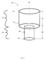
- FIG. 1 illustrates a cylindrical hole having two different diameters at different depths, according to some embodiments.
- a cylindrical hole 100 may have an upper portion 110 having a first diameter 112 that descends to a first depth 114, and a lower portion 120 having a second diameter 122 ( e.g., 1-90%, including 5-80%, including 10-80%, including 20-70% smaller than first diameter 112) that descends a second depth 124.
- Hole 100 may be defined by a central axis 130, and upper portion 110 and lower portion 120 may be coaxial.
- "Coaxial" may be a relatively local term (e.g., as in a hole that gradually curves over a distance through the earth).
- Some holes incorporate a casing (e.g., to prevent collapse when the hole is drilled through soft earth).
- a first casing 116 encases upper portion 110.
- a second casing 126 may encase lower portion 120.
- Some holes may include only one casing; some holes may include multiple casings. Some holes may not have a casing.
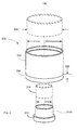
- FIG. 2 illustrates exemplary components of a drill bit assembly, according to some embodiments.
- Drill bit assembly 200 may include an inner bit 210, coupled to an outer bit 220, which is coupled to a casing ring 230.
- Drill bit assembly 200 may be designed to work with various other drilling apparatus, such as casings, drive shafts, impact hammers, collars, drill rigs, and the like.
- inner bit 210 may have a diameter (e.g., inner diameter 212) sized to attach or bond to a hollow drive tube 214.
- a drive tube 214 is threaded onto inner bit 210 at a drilling site, and then subsequent drive tubes are sequentially connected, by use of connectors 214A, as the hole is drilled further and further down with the drill bit 210.
- a drive tube may also be used as a casing.
- Casing ring 230 may have a diameter (e.g., an inner diameter 232) sized to bond or attach to a casing 234.
- casing 234 is welded to casing ring 234 at a drilling site, and additional casings may be added sequentially as drilling proceeds.
- Outer bit 220 may have an outer diameter (not shown) that is substantially the same as that (e.g., within 5%, 1 %, or even 0.1%) of casing ring 230. In some cases, outer bit 220 may have a slightly larger diameter (e.g., 0.1%, 0.5%, 1 %, or even 5% larger) than casing ring 230, which may provide for a "wide open" hole through which casing ring 230 passes.
- Outer bit 220 may be slightly smaller (e.g., 0.1%, 0.5%, 1 %, or even 5% smaller) than casing ring 230, which may provide for a "tightly fitting" hole for casing ring 230 (e.g., in soft or sandy earth).
- Outer bit 220 may include a contact height 222, that combines with the outer diameter of outer bit 220 to define a circumferential contact area between outer bit 220 and a material through which outer bit 220 drills.
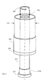
- FIG. 3 illustrates a setup for operating a drill bit assembly, according to some embodiments.
- Drilling may be described as a combination of thrust force 310 and torque 320 applied to a drill bit.
- a forward thrust force applied to inner bit 210 via drive tube 214 may push inner bit 210 in a "downward” direction, and a reverse thrust force may pull inner bit 210 in an "upward” direction.
- a torque may spin drive tube 214 and inner bit 210 about axis 130 (e.g., clockwise or counterclockwise, per the design of the drill bit assembly).
- the thrust 310 and torque is preferably applied by means of a top hammer assembly 99 (known per se, see FIG. 8A ).
- Inner bit 210 and outer bit 220 may be removably coupled.
- a torque applied to inner bit 210 may be transmitted to outer bit 220, and a thrust force applied to inner bit 210 may be transmitted to outer bit 220.
- inner bit 210 When disengaged from outer bit 220, inner bit 210 may rotate, move forward, or move in reverse independently of outer bit 220.
- Outer bit 220 and casing ring 230 may be coupled in a manner that transmits certain forces while minimizing the transmission of other forces.
- Outer bit 220 and casing ring 230 may be coupled by a thrust bearing (e.g., a journal bearing), such that outer bit 220 does not apply torque (or only applies a small amount of torque) to casing ring 230.
- a thrust force applied by inner bit 210 to outer bit 220 is transmitted to casing ring 230 by outer bit 220, which may result in outer bit 220 "pulling" a casing 234 down the hole (and/or outer bit 220 may be "pushed" downward by an apparatus, e.g. top hammer assembly, pushing on casing 234 at the surface).
- a torque may be minimally transmitted between outer bit 220 and casing ring 230, such that friction between the casing 234 and the ground does not impede the rotation of the drill bits.
- outer bit 220 may rotate while casing ring 230 (and casing 234, if bonded to casing ring 230) does not rotate, and casing ring 230 and outer bit 220 move together in forward and reverse.
- a lubricant e.g., graphite, MoS 2
- outer bit 220 may be bonded to casing ring 230.
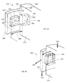
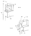
- FIGS. 4A and 4B illustrate a portion of an exemplary drill coupling, according to some embodiments.
- a drill coupling may removably couple an inner bit to an outer bit.
- drill coupling 400 may removably couple inner bit 210 to outer bit 220 via one or more male teeth on one bit (in this case, the outer bit) that engage with corresponding female teeth on the other bit (in this case, the inner bit).
- FIG. 4A illustrates drill coupling 400 in a disengaged configuration, in which inner bit 210 may move vertically independent of outer bit 220.
- FIG. 4B illustrates drill coupling 400 in an engaged configuration, in which thrust and a torque (in this case, counterclockwise as viewed from above) may be transmitted from inner bit 210 to outer bit 220.
- thrust and a torque in this case, counterclockwise as viewed from above
- drilling forces may be transmitted from a drive tube to outer bit 210 via inner bit 210, causing both inner bit 210 and outer bit 220 to rotate and drill downward.
- forward, reverse, and counterclockwise rotation forces may be transmitted from inner bit 210 to outer bit 220.
- a drill coupling may include one or more male teeth 410 and a corresponding number of female teeth 422.
- a drill coupling may include 1, 2, 3, 4, 6, 8, 10, or even more pairs of teeth.
- a drill coupling includes at least 3 pairs of teeth and at most 12, including 8, and preferably 6 pairs of teeth.
- Male teeth 410 may be sized to fit within corresponding cavities 420 in female teeth 422.
- Male teeth 410 and female teeth 422 may be disposed periodically around the facing circumferences of outer bit 220 and inner bit 210.
- a first pair of male and female teeth is sized differently than another pair (e.g., the other pairs) to control of rotational alignment between the inner and outer bits.
- the pairs of male and female teeth are interchangeable.
- An inner bit may include male teeth that engage with the corresponding female teeth of an outer bit.
- An inner bit may include female teeth that engage with the corresponding male teeth of an outer bit.
- male teeth 410 extend radially inward from an inside circumference of outer bit 220, and inner bit 210 includes corresponding female teeth 422 extending radially outward.
- Each cavity 420 and its corresponding male tooth 410 is sized such that the male tooth 410 may move into or out of its corresponding cavity 420 as inner bit 210 rotates with respect to outer bit 220.
- a tooth need not be explicitly defined.
- a male tooth may move into a cavity within a corresponding bit in which the cavity is not disposed in a female "tooth" per se.
- Male tooth 410 may have a male tooth width 412 (e.g., an angular width) that is smaller than a gap 460 between adjacent female teeth 422 (of which only one is shown in FIGS. 4A and 4B ).
- a female tooth 422 may have a female tooth width 424 that is smaller than the gap between two adjacent male teeth 410 (only one of which is shown).
- inner bit 210 may be rotated with respect to outer bit 220 (or vice versa) to a point at which male teeth 410 exit the cavities 420 of female teeth 422, allowing inner bit 210 to move forward or reverse (e.g., up or down) with respect to outer bit 220 (e.g., as in FIG. 4A ).
- inner bit 410 may be moved forward or reverse, to a distance at which male teeth 410 and female teeth 422 do not engage with each other, and inner bit 210 may rotate independently of outer bit 220.
- FIG. 4B illustrates drill coupling 400 configured to engage inner bit 210 with outer bit 220, and to transmit thrust and torque between inner bit 210 and outer bit 220.
- Torque may be transmitted from inner bit 210 to outer bit 220 via an application of angular force from torque face 450 (of cavity 420 in female tooth 422, FIG. 4A ) to corresponding torque face 452 of male tooth 410 ( FIG. 4A ).
- an overlap between the matching torque faces may define a torque area 454, through which inner bit 210 (when rotated counterclockwise as viewed from above) may apply a torque to outer bit 220.
- forces may be transmitted between inner bit 210 and outer bit 220 (via engaged teeth) using substantially (e.g., greater than 95%, 99%, or even 99.9%) normal forces across matching faces, without appreciable shear forces across these faces.
- a vector that defines a thrust face may be within 5%, 1 % or even 0.1 % of an expected drilling direction (e.g., downward).
- a torque face may be within 5%, 1 % or even 0.1% of coplanar with the expected drilling direction.
- a vector that defines a torque face may be orthogonal to an axis 130 that defines an expected drilling direction. Shear forces may be additionally reduced using a lubricant.
- inner bit 210 By transmitting force from inner bit 210 to outer bit 220 using normal forces, residual deformations that tend to attach the bits to each other (when unloaded) may be minimized. As a result, large forces may be applied during drilling, yet the inner and outer bits do not "wedge together," and removal of these forces may yield easy disengagement of the inner and outer bits.
- the engagement of inner bit 210 and outer bit 220 by normal forces results in an engagement that is easily loosened (e.g., inner bit 210 may be angularly reversed while outer bit 220 remains stationary) even when frictional forces holding outer bit 220 are small.
- a lifting force is applied to the inner bit 210, which may transmit the lifting force to the casing 234 via casing ring 230 to create a counter acting frictional force, facilitating loosening of the inner bit 210.
- a contact height 222 of outer bit 220 may be chosen according to an expected friction between the outside surface of outer bit 220 and the material through which outer bit 220 drills. For lower friction or a weak material (e.g., soil), and/or if a short casing is expected, contact height 222 may be increased enough to ensure that friction between the material and outer bit 220 is sufficient to hold outer bit 220 as inner bit 210 is rotated to disengage from outer bit 220.
- outer bit 220 may be operated to drill a short distance into the stronger material. Drilling outer bit 220 into the rock may make it easier to disengage inner bit 210 from outer bit 220, and may improve sealing between a casing and the weak material.
- a weak material e.g., soil
- a stronger (or more tightly gripping) material e.g., rock
- a hole having a diameter defined by the diameter of outer bit 220 may be drilled using both inner bit 210 and outer bit 220. By disengaging inner bit 210 from outer bit 220, the hole may be extended deeper to create a lower portion having a diameter defined by the diameter of inner bit 210.
- Engaged bits may be disengaged via a series of steps. Having drilled a hole to a first depth with both (engaged) bits, a reverse thrust may be applied to the engaged inner and outer bits (e.g., disposed as in FIG. 4B ). The drill bit assembly (incorporating drill coupling 400 and casing 234) may then be moved in reverse ( e.g ., pulled upward) to a distance that is greater than the sum of height 470 of female bit 422 above forward face 432 ( FIG. 4A ) and height 414 of male tooth 410.
- inner bit 210 may be rotated in reverse, an angular distance greater than the depth to which male teeth 410 engage with cavities 420, and less than a distance 460 at which male teeth 410 would contact adjacent female teeth 422 ( e.g ., until male teeth 410 exit their corresponding cavities 420). Rotation may then be stopped, and inner bit 210 may be thrust forward (while outer bit 220 remains stationary) a distance greater than the sum of height 414 of male tooth 410 and height 470 of female tooth 422, so that the female teeth 422 are "below” or "past” male teeth 410. Inner bit 210 may then be rotated independently of outer bit 220, and drilling may continue using inner bit 210. In some embodiments the casing 234 (with the casing ring 230 and outer bit 220) may be subsequently pushed downward (from an apparatus above) to abut and seal against the bottom of the outer hole.
- FIGS. 5A and 5B illustrate a portion of a drill coupling, according to some embodiments.
- Drill coupling 500 illustrates an example in which male teeth 510 extend radially outward from an outer circumference of inner bit 210 (not shown).
- Male teeth 510 removably disengage with corresponding cavities 520 in female teeth 522, that may extend radially inward from outer bit 220.
- Inner bit 210 may be rotated to cause engagement between male teeth 510 and female teeth 520 (clockwise from above as shown in FIG. 5A ).
- Inner bit 210 may be rotated to disengage male teeth 510 from female teeth 520 (as shown in FIG. 5B ), allowing for upward or downward motion of inner bit 210 with respect to outer bit 220.
- When engaged (as in FIG.
- drill coupling 500 may transmit thrust and (in this case, clockwise) torque from inner bit 210 to outer bit 220.
- inner bit 210 may be rotated counterclockwise to disengage male teeth 510 from cavities 520 ( e.g ., as in FIG. 5B ).
- Inner bit 210 and teeth 510 may then be thrust forward without rotation, until male teeth 510 clear female teeth 522 (e.g., by moving inner bit 510 forward a distance greater than the sum of a lower height 570 of female tooth 522 and the height 572 of male tooth 510). Rotation of inner bit 210 may then resume without causing rotation of outer bit 220.
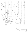
- FIGS. 6A and 6B are cross section illustrations of engaged and disengaged configurations, according to some embodiments.
- drill bit assembly 600 may have drill coupling 400 configured to engage inner bit 210 and outer bit 220.
- drill bit assembly 600 may have drill coupling 400 configured to disengage inner bit 210 from outer bit 220 ( e.g ., to allow inner bit 210 to move downward independent of outer bit 220).
- Outer bit 220 may be coupled to casing ring 230 via a thrust ring 610.
- Thrust ring 610 may include a ring extending radially from one of outer bit 220 and casing ring 230, sized to fit within an annular groove in the other of outer bit 220 and casing ring 230.
- an outer surface of inner bit 210 and an inner surface of outer bit 220 may have facing grooves, and a thrust ring may be disposed within the grooves to transmit thrust between the bits (e.g., as a piston ring is disposed within a piston).
- Thrust ring 610 may provide for the transmission of a forward and/or reverse thrust force between outer bit 220 and casing ring 230. Thrust ring 610 may be shaped to minimized the transmission of torque from outer bit 220 to casing ring 230, such that outer bit 220 may rotate while casing ring 230 does not rotate.
- a thrust ring may include a "male" feature (e.g., a ring extending from a surface) and a corresponding "female” feature (e.g., a race within which the ring slides).
- a thrust ring and/or casing ring may be cut or split longitudinally and stretched to fit around outer bit 220; it may then be welded along the cut.
- casing ring 230 may be connected to a casing 234 via a bond 620.
- Drive tube 214 may be connected to inner bit 210 via a bond 622, wherein preferably the inner bit 210 is arranged with an upwardly protruding annular collar 210A having an inner diameter adapted to fit the outer diameter of the front end 214A of the drive tube 214, to enable overlapping introduction of the front end 214A of the drive tube 214 within the annular collar 210A of the inner bit 210.
- a bond may include a weld, one or more bolts, an adhesive, a threaded fitting, a rivet, and the like.
- a bond may provide for the transmission of angular (e.g., torque), shear and thrust forces between bound objects.
- drive tube 214 may be threaded into inner bit 210, and casing ring 230 may be welded to casing 234.
- FIG. 6A illustrates fittings 630, that may be sized to receive cutting tool inserts 632.
- An exemplary cutting tool insert may include a tool steel, a carbide, a nitride, a cemented carbide or carbonitride, a diamond or diamond-like-carbon composite, or coatings thereof.
- FIG. 6A illustrates a drilling fluid passage 640 in inner bit 210.
- Passage 640 may provide for fluid communication between an interior volume (e.g., of inner bit 210 and drive tube 214) and an exterior side (e.g., the drilling face) of inner bit 210.
- an exterior passage 650 provides for fluid communication between the exterior side and a volume between drive tube 214 and casing 234, whereby preferably said exterior passages 650 include outlet openings 650A arranged at the outside of the collar portion 210A of the inner bit 210.
- FIG. 6A The engaged configuration shown in FIG. 6A may be operated to rotate both inner bit 210 and outer bit 220 while casing ring 230 and casing 234 do not rotate ( e.g. , if they are held by friction with the earth).
- FIG. 6B illustrates a disengaged configuration of drill bit assembly 600, in which inner bit 210 has been disengaged from outer bit 220. Inner bit 210 may continue to drill while outer bit 220 remains stationary. A difference in diameter between that of inner bit 210 and that of outer bit 220 may yield a corresponding difference in hole diameter as inner bit 210 descends past outer bit 220.
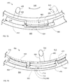
- FIGS. 7A and 7B illustrate plan views (from above) of a coupling in engaged and disengaged configurations (respectively), according to some embodiments.
- Female teeth 422 (of which only one is shown) have cavities 420 shaped to engage with male teeth 410.
- a total thrust area may describe the sum of the thrust areas 434 between the thrust surfaces of corresponding male and female teeth.
- a total torque area may describe the sum of the torque areas between the torque faces of corresponding male and female teeth (not shown).
- Increasing the number of teeth (at constant height) may increase the torque area. Decreasing the number of teeth (and increasing tooth width) may increase the thrust area.
- the relative ratio of thrust area to torque area may be chosen according to the requirements of the site to be drilled.
- a configuration having more teeth may have higher torque area and lower thrust area.
- a configuration having fewer teeth may have lower torque area and higher thrust area. Tooth and cavity height may be increased to increase torque area.
- female teeth 422 are disengaged from male teeth 410, and inner bit 210 may move forward or reverse (in/out of the page) with respect to outer bit 220.
- male teeth 410 are disposed within cavities 420 of female teeth 422, and thrust and (in this case, clockwise) torque may be transmitted from inner bit 210 to outer bit 220.
- An outer passage 650 may provide for fluid communication between inner passage 640 and a gap 710 between adjacent pairs of engaged teeth. Gap 710 may be defined by a distance 712 between a side of a female tooth 422 and the facing side of an adjacent male tooth 410 when the drill coupling is engaged, and a distance between the outside of inner bit 210 and inside of outer bit 220.
- Passage 640 may be in fluid communication with a volume within drive tube 214 ( FIG. 3 ), and passage 650 may provide fluid communication from passage 640 to gap 710.
- Gap 710 may be in fluid communication with the volume between drive tube 214 and casing 234 ( FIG. 6 ) which may extend to the surface of the material being drilled. Gap 710 may form at least a portion of a passage (e.g., passage 650).
- a drilling fluid e.g., air, water, mud, and the like
- Fluid may be pumped in the opposite direction.
- various passages may be filled ( e.g ., with cement, concrete, and the like) by pumping a settable fluid.
- concrete 730 may be pumped down drive tube 214 as air escapes up through the volume between drive tube 214 and casing 234.
- Concrete may possibly also be pumped down through the volume between drive tube 214 and casing 234 as air escapes up through drive tube 214 (or vice versa ).
- Concrete 730 may be pumped until it fills both the interior of drive tube 214 and the volume between drive tube 214 and casing 234.
- the concrete may set, to form a composite pillar having concrete reinforced by ( e.g ., steel) drive tube 214 and casing 234.
- a surface e.g., an exterior of a drive tube and/or an interior of a casing
- a pattern or texture e.g., ridges, grooves, knobs, and the like
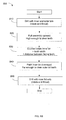
- FIG. 8A describes a method for drilling a hole having multiple diameters, according to some embodiments, e.g. to make a composite pillar as shown in FIG. 8A .
- Method 800 includes steps 810, 820, 830, 840, and 850.
- a hole 100 is drilled with a drill bit assembly 201, 230 configured to drill with both inner and outer bits.
- the drill bit assembly is pulled upward (reverse) a distance large enough that the male teeth on one bit will clear the female teeth on the other bit.
- the inner bit is counter-rotated a short distance (e.g., less than gap 460) to disengage the male teeth from their corresponding female teeth.
- step 840 the inner bit is thrust downward (forward) a distance large enough that the male and female teeth clear each other.
- drilling continues with only the inner bit to form a hole 120 of a smaller diameter.
- a drilling fluid e.g ., air
- concrete 730 may be pumped ( e.g ., down the drive tube) to fill a casing bonded to the casing coupling of the drill bit assembly and/or the drive tube driving the inner bit.
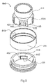
- FIG. 9 illustrates a perspective illustration of an exemplary drill bit assembly, according to some embodiments.
- Drill bit assembly 900 includes an inner bit 210, an outer bit 220, and a casing ring 230.
- outer bit 220 includes four pairs of male teeth 410 that engage with cavities 420 in corresponding and female teeth 422.
- FIG. 9 illustrates drill bit assembly 900 as viewed from above, with the various components "expanded" for clarity.
- a drill bit assembly may be assembled by cutting a casing ring (e.g., longitudinally) and fitting the casing ring around the outer bit (e.g., as a piston ring is fit into a corresponding race in a piston).
- a casing ring may be subsequently welded or otherwise bonded across the cut, typically in a manner that does not impede the performance of thrust ring 610.
- FIG. 10 illustrates another view of a drill bit assembly, according to some embodiments.
- FIG. 10 illustrates a view of drill bit assembly 900 as viewed from below, expanded for clarity.
- a face of a tooth may include a divot 1010.
- Divot 1010 may be a machining feature that (inter alia) removes portions of a torque face that would be non-parallel with corresponding portions on a facing tooth or cavity. Divots 1010 may minimize the creation of shear forces between male and female teeth, which may reduce undesired binding or wedging during use.
- FIG. 10 also illustrates corresponding male and female features of thrust ring 610.
- FIGS. 11A, 11B, and 11C illustrate various views of a drill bit assembly, according to some embodiments.
- FIG. 11A illustrates drill bit assembly 900 in an "assembled" configuration.
- a drive tube may be attached to inner bit 210, and optionally a casing may be attached to casing ring 230.
- FIG. 11B illustrates a plan view (from below, facing opposite the drilling direction) of drill bit assembly 900.
- FIG. 11B provides additional illustration for an exemplary embodiment in which passages 640 and 650 provide for fluid communication between the volume within a drive tube and the volume between the drive tube and a casing (see FIG. 3 ).
- FIG. 11C illustrates an assembled drill bit assembly 900 as viewed in cross section, according to the section "A" shown in FIG. 11B .
Landscapes
- Engineering & Computer Science (AREA)
- Life Sciences & Earth Sciences (AREA)
- Geology (AREA)
- Mining & Mineral Resources (AREA)
- Physics & Mathematics (AREA)
- Environmental & Geological Engineering (AREA)
- Fluid Mechanics (AREA)
- General Life Sciences & Earth Sciences (AREA)
- Geochemistry & Mineralogy (AREA)
- Mechanical Engineering (AREA)
- Earth Drilling (AREA)
- Processing Of Stones Or Stones Resemblance Materials (AREA)
Applications Claiming Priority (1)
| Application Number | Priority Date | Filing Date | Title |
|---|---|---|---|
| SE1350289 | 2013-03-11 |
Publications (2)
| Publication Number | Publication Date |
|---|---|
| EP2778338A2 true EP2778338A2 (fr) | 2014-09-17 |
| EP2778338A3 EP2778338A3 (fr) | 2016-07-20 |
Family
ID=50289379
Family Applications (1)
| Application Number | Title | Priority Date | Filing Date |
|---|---|---|---|
| EP14158835.0A Withdrawn EP2778338A3 (fr) | 2013-03-11 | 2014-03-11 | Ensemble trépan |
Country Status (1)
| Country | Link |
|---|---|
| EP (1) | EP2778338A3 (fr) |
Cited By (1)
| Publication number | Priority date | Publication date | Assignee | Title |
|---|---|---|---|---|
| WO2018116140A1 (fr) * | 2016-12-19 | 2018-06-28 | Flexidrill Limited | Trépan hybride |
Citations (2)
| Publication number | Priority date | Publication date | Assignee | Title |
|---|---|---|---|---|
| WO1996018798A1 (fr) | 1994-12-13 | 1996-06-20 | Ilomaeki Valto | Procede de forage et ensemble trepan pour la realisation de ce procede |
| WO1997000371A1 (fr) | 1995-06-15 | 1997-01-03 | Ian Graeme Rear | Ensemble marteau de fond de puits |
Family Cites Families (4)
| Publication number | Priority date | Publication date | Assignee | Title |
|---|---|---|---|---|
| US5839519A (en) * | 1996-11-08 | 1998-11-24 | Sandvik Ab | Methods and apparatus for attaching a casing to a drill bit in overburden drilling equipment |
| FI109143B (fi) * | 2001-04-04 | 2002-05-31 | Oy Atlas Copco Rotex Ab | Menetelmä poraukseen ja porauslaitteisto |
| US7607496B2 (en) * | 2007-03-05 | 2009-10-27 | Robert Charles Southard | Drilling apparatus and system for drilling wells |
| SE533272C2 (sv) * | 2008-12-18 | 2010-08-03 | Sandvik Intellectual Property | Borrverktyg för slående bergborrning samt förbrukningskit, ringborrkrona och slagsko härför |
-
2014
- 2014-03-11 EP EP14158835.0A patent/EP2778338A3/fr not_active Withdrawn
Patent Citations (2)
| Publication number | Priority date | Publication date | Assignee | Title |
|---|---|---|---|---|
| WO1996018798A1 (fr) | 1994-12-13 | 1996-06-20 | Ilomaeki Valto | Procede de forage et ensemble trepan pour la realisation de ce procede |
| WO1997000371A1 (fr) | 1995-06-15 | 1997-01-03 | Ian Graeme Rear | Ensemble marteau de fond de puits |
Cited By (1)
| Publication number | Priority date | Publication date | Assignee | Title |
|---|---|---|---|---|
| WO2018116140A1 (fr) * | 2016-12-19 | 2018-06-28 | Flexidrill Limited | Trépan hybride |
Also Published As
| Publication number | Publication date |
|---|---|
| EP2778338A3 (fr) | 2016-07-20 |
Similar Documents
| Publication | Publication Date | Title |
|---|---|---|
| RU2594032C2 (ru) | Системы и способы для использования прохода сквозь подземные пласты | |
| CN104695865B (zh) | 微型隧道掘进系统和设备 | |
| US6182776B1 (en) | Overburden drilling apparatus having a down-the-hole hammer separatable from an outer casing/drill bit unit | |
| US7243737B2 (en) | Interchangeable reamer | |
| EP2395154B1 (fr) | Procédée et dispositif de stabilisation d'un sol. | |
| CN101027456B (zh) | 底部钻具组合 | |
| US9611695B2 (en) | Dual pipe drilling head with improved bearing retention structure | |
| US20130233624A1 (en) | Drilling apparatus having head | |
| NO332540B1 (no) | Utvidbart roroppheng med tilpasset kilesystem. | |
| EP2673450B1 (fr) | Perforateur de fond de trou à annulaire | |
| US12286843B2 (en) | Dual pipe drill head quick interchange joint | |
| US20240116114A1 (en) | Integrated drilling injection and extraction device and method | |
| US7182156B2 (en) | System for overburden drilling | |
| EP2778338A2 (fr) | Ensemble trépan | |
| EP4413228A1 (fr) | Dispositif de forage à expansion | |
| CN112942477B (zh) | 一种钢管桩遇到孤石快速的破碎工具及施工方法 | |
| US9290993B2 (en) | Method and system for installation of in-ground conduit | |
| JP5853032B2 (ja) | ダウンザホール工法による掘削時に、ドリルストリングの空隙と周囲の素材との間に連通を形成するための方法及び装置 | |
| US20150308196A1 (en) | Casing drilling under reamer apparatus and method | |
| US12448845B1 (en) | Apparatus with fluid powered drive assemblies and method of fabrication | |
| AU2020347939B2 (en) | Drill assembly and method of using same | |
| CN105568966A (zh) | 楔形插扣t形桩钻搅机 | |
| JPH05231085A (ja) | 掘削工法及び装置 | |
| CN113513261A (zh) | 一种辅助冲击回转式凿岩机完成开槽作业的钻杆导向装置 | |
| JPH08144679A (ja) | 掘削工具 |
Legal Events
| Date | Code | Title | Description |
|---|---|---|---|
| 17P | Request for examination filed |
Effective date: 20140311 |
|
| AK | Designated contracting states |
Kind code of ref document: A2 Designated state(s): AL AT BE BG CH CY CZ DE DK EE ES FI FR GB GR HR HU IE IS IT LI LT LU LV MC MK MT NL NO PL PT RO RS SE SI SK SM TR |
|
| AX | Request for extension of the european patent |
Extension state: BA ME |
|
| PUAI | Public reference made under article 153(3) epc to a published international application that has entered the european phase |
Free format text: ORIGINAL CODE: 0009012 |
|
| PUAL | Search report despatched |
Free format text: ORIGINAL CODE: 0009013 |
|
| AK | Designated contracting states |
Kind code of ref document: A3 Designated state(s): AL AT BE BG CH CY CZ DE DK EE ES FI FR GB GR HR HU IE IS IT LI LT LU LV MC MK MT NL NO PL PT RO RS SE SI SK SM TR |
|
| AX | Request for extension of the european patent |
Extension state: BA ME |
|
| RIC1 | Information provided on ipc code assigned before grant |
Ipc: E21B 10/00 20060101AFI20160615BHEP |
|
| R17P | Request for examination filed (corrected) |
Effective date: 20170111 |
|
| RBV | Designated contracting states (corrected) |
Designated state(s): AL AT BE BG CH CY CZ DE DK EE ES FI FR GB GR HR HU IE IS IT LI LT LU LV MC MK MT NL NO PL PT RO RS SE SI SK SM TR |
|
| STAA | Information on the status of an ep patent application or granted ep patent |
Free format text: STATUS: THE APPLICATION IS DEEMED TO BE WITHDRAWN |
|
| 18D | Application deemed to be withdrawn |
Effective date: 20181002 |