EP2778525A1 - Traversée de toit avec embout de cheminée - Google Patents
Traversée de toit avec embout de cheminée Download PDFInfo
- Publication number
- EP2778525A1 EP2778525A1 EP13158582.0A EP13158582A EP2778525A1 EP 2778525 A1 EP2778525 A1 EP 2778525A1 EP 13158582 A EP13158582 A EP 13158582A EP 2778525 A1 EP2778525 A1 EP 2778525A1
- Authority
- EP
- European Patent Office
- Prior art keywords
- head part
- passage openings
- exhaust
- roof duct
- wind
- Prior art date
- Legal status (The legal status is an assumption and is not a legal conclusion. Google has not performed a legal analysis and makes no representation as to the accuracy of the status listed.)
- Withdrawn
Links
- 238000007373 indentation Methods 0.000 claims description 16
- 238000004891 communication Methods 0.000 claims description 8
- 230000007423 decrease Effects 0.000 claims description 4
- 238000010438 heat treatment Methods 0.000 description 8
- 230000000694 effects Effects 0.000 description 5
- 230000035515 penetration Effects 0.000 description 4
- 230000015572 biosynthetic process Effects 0.000 description 3
- 238000013461 design Methods 0.000 description 3
- 238000006073 displacement reaction Methods 0.000 description 3
- 239000012530 fluid Substances 0.000 description 3
- 239000011324 bead Substances 0.000 description 2
- 238000002485 combustion reaction Methods 0.000 description 2
- 230000003111 delayed effect Effects 0.000 description 2
- 210000001015 abdomen Anatomy 0.000 description 1
- 238000009833 condensation Methods 0.000 description 1
- 230000005494 condensation Effects 0.000 description 1
- 230000001419 dependent effect Effects 0.000 description 1
- 238000011161 development Methods 0.000 description 1
- 230000018109 developmental process Effects 0.000 description 1
- 238000002955 isolation Methods 0.000 description 1
- 230000000116 mitigating effect Effects 0.000 description 1
- 238000012986 modification Methods 0.000 description 1
- 230000004048 modification Effects 0.000 description 1
Images




Classifications
-
- F—MECHANICAL ENGINEERING; LIGHTING; HEATING; WEAPONS; BLASTING
- F23—COMBUSTION APPARATUS; COMBUSTION PROCESSES
- F23L—SUPPLYING AIR OR NON-COMBUSTIBLE LIQUIDS OR GASES TO COMBUSTION APPARATUS IN GENERAL ; VALVES OR DAMPERS SPECIALLY ADAPTED FOR CONTROLLING AIR SUPPLY OR DRAUGHT IN COMBUSTION APPARATUS; INDUCING DRAUGHT IN COMBUSTION APPARATUS; TOPS FOR CHIMNEYS OR VENTILATING SHAFTS; TERMINALS FOR FLUES
- F23L17/00—Inducing draught; Tops for chimneys or ventilating shafts; Terminals for flues
- F23L17/02—Tops for chimneys or ventilating shafts; Terminals for flues
- F23L17/12—Devices for fastening the top or terminal to chimney, shaft, or flue
-
- F—MECHANICAL ENGINEERING; LIGHTING; HEATING; WEAPONS; BLASTING
- F23—COMBUSTION APPARATUS; COMBUSTION PROCESSES
- F23L—SUPPLYING AIR OR NON-COMBUSTIBLE LIQUIDS OR GASES TO COMBUSTION APPARATUS IN GENERAL ; VALVES OR DAMPERS SPECIALLY ADAPTED FOR CONTROLLING AIR SUPPLY OR DRAUGHT IN COMBUSTION APPARATUS; INDUCING DRAUGHT IN COMBUSTION APPARATUS; TOPS FOR CHIMNEYS OR VENTILATING SHAFTS; TERMINALS FOR FLUES
- F23L17/00—Inducing draught; Tops for chimneys or ventilating shafts; Terminals for flues
- F23L17/02—Tops for chimneys or ventilating shafts; Terminals for flues
- F23L17/04—Balanced-flue arrangements, i.e. devices which combine air inlet to combustion unit with smoke outlet
-
- F—MECHANICAL ENGINEERING; LIGHTING; HEATING; WEAPONS; BLASTING
- F23—COMBUSTION APPARATUS; COMBUSTION PROCESSES
- F23J—REMOVAL OR TREATMENT OF COMBUSTION PRODUCTS OR COMBUSTION RESIDUES; FLUES
- F23J2213/00—Chimneys or flues
- F23J2213/50—Top cover
-
- F—MECHANICAL ENGINEERING; LIGHTING; HEATING; WEAPONS; BLASTING
- F23—COMBUSTION APPARATUS; COMBUSTION PROCESSES
- F23J—REMOVAL OR TREATMENT OF COMBUSTION PRODUCTS OR COMBUSTION RESIDUES; FLUES
- F23J2900/00—Special arrangements for conducting or purifying combustion fumes; Treatment of fumes or ashes
- F23J2900/13005—Protections for chimneys or flue tops against external factors, e.g. birds
Definitions
- the invention is directed to a roof duct for a chimney, which has an exhaust pipe, which is provided with a wind deflector device.
- a roof duct is used for the removal of exhaust gas from a heating system and is suitable in today's time, especially for the room air independent operation of condensing boilers.
- the exhaust gas is led outside via an exhaust pipe to the outside.
- the exhaust pipe is concentrically surrounded by a Zu Kunststoffrohr, wherein in the annular gap between the inlet pipe and the exhaust pipe, the supply air, which is needed for the combustion process of the heating system, is sucked.
- the invention has for its object to provide a solution that provides a structurally simple way and cost an improved roof penetration, which is suitable to mitigate wind and rain without simultaneous risk of icing due to condensation formation. At the same time a roof penetration is to be created, which is suitable to compensate for linear expansion of the exhaust pipe in a clever and efficient way.
- the roof duct according to the invention for a chimney has an exhaust pipe, which is provided with a wind deflector device.
- the wind deflector device comprises a basic body which extends substantially in the direction of the longitudinal axis of the exhaust pipe and which has in its hollow interior a receptacle which serves for fluid-tight connection to the exhaust pipe, and a dome-shaped head part.
- the receptacle extends in the interior of the hollow interior up to an exhaust gas opening which is formed in a cover wall closing a longitudinal end of the main body.
- the substantially hollow head part is detachably attached to the outer side of the base body at the longitudinal end having the cover wall and covers the exhaust gas opening.
- the head part has on the inside columnar wind deflection elements, which extend in imaginary extension of the receptacle and which are supported on the exhaust gas opening or in the region of the exhaust gas opening on the cover wall.
- the head part has, via the wind deflecting elements, passage openings which are in fluid communication with the exhaust gas opening and which are formed in the area of its lateral surface lying outside of the wind deflecting elements and outside the exhaust gas opening.
- a roof penetration is provided in a structurally simple manner, which is characterized by an improved wind deflection.
- the inventive design of the wind deflector prevents direct wind into the exhaust port and thus into the exhaust pipe. This is possible because the head part in the region of its apex has no openings at all, in which winds could fall from above into the exhaust pipe. Although formed in the outer region of the head part through openings through which exits the exhaust gas in the open air during normal operation, although allow wind into the interior of the head part. However, arranged in the interior of the head part Windablenkieri divert incoming winds such that their flow rate is reduced so much that the incoming wind can not produce under pressure and overpressure in the exhaust pipe and also the outlet of the exhaust gas is not blocked.
- the inventive combination and arrangement of wind deflectors and passages beyond a direct insight into the exhaust port and the exhaust pipe from the outside is not possible from the outside, so that incident winds can not get into the exhaust pipe and affect the exhaust flow.
- the invention provides in an embodiment that the exhaust pipe is attached to the base body and the main body has guide ribs extending in the longitudinal direction of the exhaust pipe and on which a the exhaust pipe concentrically surrounding and along the guide ribs movable supply air pipe is applied.
- the Zubuchrohr is movable in this manner relative to the exhaust pipe along the guide ribs to compensate for linear expansion of the exhaust pipe.
- the guide ribs advantageously form a gap through which supply air from the annular gap between the base body and the supply air pipe can enter an annular gap leading to the heating system between the supply air pipe and the exhaust pipe.
- no specially prepared through holes must be formed in the supply air pipe, so that supply air can get into the annular gap between the supply air pipe and the exhaust pipe.
- the body is provided on its outer side with a plurality of wells extending in the longitudinal direction of the body and uniformly are spaced.
- the wind can also be derived and broken at the head part, it is advantageous if the head part is provided with indentations, which are formed on the outside of the head part and extending from the pole of the head part in the direction of its base at least between the passage openings ,
- the invention provides in a further embodiment that the passage openings are formed in a circular arc and arranged in groups, preferably in groups, each having four passage openings, along meridian lines. According to this group-wise arrangement, several, for example four, passage openings are always superimposed on the outside of the head part, i. starting from the base in the direction of the pole of the head part, arranged.
- the head part has according to the number of groups of passage openings on respective wind deflecting elements, which are arranged in extension of the groups in the interior of the head part and shield the exhaust port from direct windfall.
- the invention provides in a further embodiment that a respective wind deflector element in the Is formed substantially U-shaped, wherein the two legs of the respective U-shaped Windablenkelements extend substantially along the radii of the arc formed by a respective group of passages from the edge of the exhaust port in the direction of the corresponding group of through holes, and wherein the two legs connecting web extends substantially along an arc of the edge of the exhaust port.
- the two legs of a respective wind deflector extend in the direction of the group of through openings, so that directly incident wind catches in the belly of the U-shaped wind deflector and is thereby kept away from the exhaust opening.
- the U-shaped wind deflector thus shields the exhaust port from wind.
- the center angle of a circular arc between adjacent groups of passages is at least 20 °, but at most 35 °. In the lateral surface of the head portion of this circular arc portion, the indentations extend.
- the invention providing that the midpoint angle of a circular arc formed by a respective group of passage openings is at least 10 ° but at most 25 ° ° is. This angle describes the size of the opening of the group of passage openings, wherein eight groups of passage openings are provided for this embodiment.
- the wind deflector extends perpendicularly from the base of the head part in the direction of the lateral surface and shields the exhaust port inwardly from.
- the exhaust gas from the exhaust port through the passages can reach the outside, is provided in a further embodiment that between the free ends of the two legs of the respective Windablenkiata and the lateral surface of the head portion serving for the passage of exhaust gas from the exhaust port gap is trained. Through this gap, the exhaust gas can then reach the passage openings, from where it flows into the open air.
- the passage openings are formed in a circular arc and arranged in groups, preferably in groups, each with three passage openings, inclined at an angle between 25 ° and 35 ° with respect to a meridian lines.
- the arrangement of the passages, which is inclined in the circumferential direction, is intended to reduce the influence of incident winds on a group of passage openings, because the inclination affects the incident wind in each of the passage openings of the group considered.
- the center angle of a circular arc between adjacent groups of passage openings is at least 10 °, but at most 25 °. Due to the inclined arrangement of the group of passages, the indentations present in this section also run inclined to a meridian line serving as a reference.
- the center angle of a circular arc formed by a respective group of passage openings is at least 12 °, but at most 25 °.
- a total of twelve groups are provided, so that the proportion of the passage openings compared to the running between them from the base to the pole of the head part shell sections tends to be small.
- the alternative head part gives the impression that the surface of the head part has more passage openings than closed surfaces.
- this impression is reinforced in a further embodiment of the alternative head part, characterized in that the portion of the lateral surface of the head part between adjacent groups of passage openings has at least one intermediate passage opening.
- this intermediate passage opening is formed very close to the base of the head part and next to the lowermost passage opening.
- a respective wind deflection element is formed by two guide walls which, starting from the lateral surface, extend from the end points of a circular arc formed by a respective group of passage openings in the direction of the center of the head part according to the inclination of the arrangement of the group.
- At least one of the two baffles extends to the exhaust gas opening and the free end is provided with deflecting lugs pointing in opposite circumferential directions.
- the incident wind is initially delayed due to friction due to the guide wall, wherein the deflection is designed such that the sunken wind is deflected towards itself and thereby brakes itself.
- This is possible by the Umlenkan accounts, wherein the effect of "self-braking" occurs in conjunction with an adjacent Windablenkelement.
- the invention provides in a further embodiment, that the gap between a guide wall of a wind deflector and a guide wall of an adjacent Windablenkelements V-shaped, wherein the cross-section decreases to the center of the head part. As a result of the cross-section decrease the gap acts as a brake for incident through the intermediate passage openings winds.
- FIG. 1 is a perspective view of a roof duct 1 according to the invention for a fireplace or for a room air independent operation of a condensing boiler, not shown, or a heating system shown
- FIG. 2 an itemized view of in FIG. 1 illustrated roof duct 1 shows.
- the roof duct 1 comprises an internal exhaust pipe 2, which is surrounded concentrically by a supply air pipe 3.
- the exhaust pipe 2 and the supply air pipe 3 are in fluid communication with a wind deflector device 4, as will be described in more detail below.
- a roof duct 1 may also have only the exhaust pipe 2 and no supply air pipe, wherein the exhaust pipe is still with the wind deflector device. 4 is provided.
- the wind deflector device 4 has a main body 5 and a head part 6.
- the head part 6 is dome-shaped and formed approximately hemispherical, whereas the base body 5 is formed substantially hollow cylindrical and extending in the direction of the longitudinal axis 7 of the exhaust pipe.
- a longitudinal end 21 of the main body 5 (see, for example FIG. 2 ) is closed with a cover wall 8, wherein in the middle of the cover wall 8, an exhaust port 9 is formed.
- a plurality of depressions 11 are formed in the outer side 10 of the main body 5, which extend in the direction of the longitudinal axis 12 of the main body 5 and are uniformly spaced from each other.
- the hollow cylindrical base body 5 has in its hollow interior 13 a receptacle 14 for the exhaust pipe 2, which extends in the interior of the hollow interior 13 to the cover wall 8 and is fluidically connected to the exhaust port 9.
- a receptacle 14 for the exhaust pipe 2, which extends in the interior of the hollow interior 13 to the cover wall 8 and is fluidically connected to the exhaust port 9.
- the receptacle 14 is the exhaust port 9 with the exhaust pipe 2 in flow communication.
- the receptacle 14 serves for fluid-tight connection of the base body 5 with the exhaust pipe 2, wherein the exhaust gas exiting the exhaust port 9 and is passed through the head part 6 to the outside.
- the receptacle 14 is formed like a sleeve for fluid-tight connection with the exhaust pipe 2.
- the main body 5 thus has in its hollow interior 13 serving for fluid-tight connection with the exhaust pipe 2 and sleeve-like receptacle 14 for the exhaust pipe 2, wherein the receptacle 14 extends concentrically inside the hollow interior 13 up to the exhaust opening 9 formed in the cover wall 8.
- the main body 5 a collar 18 which protrudes from the top wall 9 and serves for the return and / or for holding accumulating condensate.
- the top wall 8 drops to the exhaust port 9 out, so that accumulating condensate can be returned to the exhaust port 9 and thus the risk of ice formation can be reduced.
- a plurality of guide ribs 23 are formed on the inner periphery of the main body 5, which extend in the direction of the longitudinal axis 12 of the main body 2 and the longitudinal axis 7 of the exhaust pipe 2.
- the exhaust pipe 2 concentrically surrounding and along the guide ribs 23 movable Zu Kunststoffrohr 3 at.
- the Zu povertyrohr 3 is movable relative to the exhaust pipe along the guide ribs 23 with the aid of the guide ribs 23 to compensate for linear expansion of the exhaust pipe 2.
- FIG. 3 are further arranged inside the head part 6 arranged and columnar wind deflectors 19 which extend in an imaginary extension of the receptacle 14 and the exhaust port 9 is substantially perpendicular with respect to the top wall 8 within the head part 6.
- the wind deflection elements 19 are based on the edge 20 of the exhaust port 9 evenly spaced, wherein the columnar Windablenkieri 19 substantially rest on the cover wall 8.
- the wind deflection elements 19 will be discussed in detail below.
- the substantially hollow head part 6 is at the longitudinal end 21 of the base body 5, on which the cover wall 8 is arranged, externally attached to the base body 5 releasably and covers in the attached state, the exhaust port 9.
- the head part 6 is detachable with the main body 5 in positive engagement can be brought, what can serve a latching connection, a screw or a bayonet connection.
- the collar 18 on the inside formed latching lugs 31 which integrally formed with the head part 6 locking elements 32 (see, for example Figures 5 or 7 ) cooperate and realize a detachable and positive connection between the head part 6 and base 5.
- the head part 6 on the base body 5 in the manner of a rotary closure releasably or removably attachable by the head part 6 is attached and then, preferably by about 20 ° -30 °, rotated.
- the head part 6 must necessarily be removable, since in some countries or regions an open mouth of the exhaust pipe 2 is allowed and thus the head part 6 is not needed. In countries or regions in which the head part 6 is required and even mandatory, the head part 6 must be dismantled, for example, by a chimney sweep so that it can take the view into the exhaust pipe 2.
- FIG. 4 the main body 5 is shown, wherein in this illustration the main body 5 is connected both to the exhaust pipe 2 and to the supply air pipe 3.
- the exhaust gas flows through the inner exhaust pipe 2 in the direction of the exhaust port 9 (see arrow 24 for the exhaust gas flow), while the heating system supplied supply air flows in the annular gap 25 between the exhaust pipe 2 and supply air pipe 3 down (see arrows 26 for the supply air flow).
- the supply air is sucked in via an annular gap formed between the Zuluftrohr 3 and the main body 5 27 from below, so that the supply air initially flows upward within the annular gap 27 and then deflected into the annular gap 25 becomes.
- the guide ribs 23 advantageously form a gap 29, through which the supply air from the annular gap 27 between main body 5 and supply air pipe 3 can reach into the annular gap 25 leading to the heating system between supply air pipe 3 and exhaust pipe 2.
- the guide ribs 23 advantageously form a gap 29, through which the supply air from the annular gap 27 between main body 5 and supply air pipe 3 can reach into the annular gap 25 leading to the heating system between supply air pipe 3 and exhaust pipe 2.
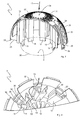
- FIGS. 5 to 8 different views of a first embodiment of a head part 6 are shown already in the FIGS. 1 to 3 was seen and generally described.
- the head part 6 has in the vicinity of its base 33 peripherally formed locking elements 32, which serve for releasable connection to the base body 5.
- Above the individual latching elements 32 extend from the base 33 in the direction of the pole 34 of the head part 6 three mutually parallel indentations 35.
- These indentations 35 are formed on the outer side 39 of the head part 6 and extend along or parallel to a meridian line 36 (see FIG. 5 ), ie a semicircle passing through the pole 34, which is perpendicular to the base 33.
- the indentations 35 terminate in front of the pole 34.
- the head part 6 is provided with indentations 35, which are formed on the outer side 39 of the head part 6 and extending from the pole 34 of the head part 6 in the direction of its base 33 at least between passage openings 38 of the head part. 6 extend.
- indentations 35 and the pole 35 further recesses 37 are provided which extend in the entire upper sector of the approximately hemispherical head part 6 from the pole 34 in the direction of the base 33.
- the recesses 37 have different depths, and it is also conceivable that Form recesses 37 with identical depths.
- the indentations 35 and recesses 37 are intended to divert and / or break the wind entering the roof duct 1.
- the head part 6 in addition to the three parallel to each other from the pole 34 of the head part 6 to the base 33 extending indentations 35 more passage openings 38 which are formed in the lateral surface 40 of the head part 6.
- the passage openings 38 are arranged in pairs to form groups 41, wherein a respective group 41 according to the first embodiment of the head part 6 are each assigned four passage openings 38.
- the paired indentations 35 which are formed on the outer side 39 of the head part 6 and extending from the pole 34 of the head part 6 in the direction of its base 33 at least between the passage openings 38, and the groups 41 of the passage openings 38 are alternately provided and determine the shape of the head part 6.
- the passage openings 38 of the head part 6 are formed in a circular arc and in the groups 41 along meridian lines (a meridian line 36 is exemplified in FIG FIG. 5 shown).
- the passage openings 38 are in flow communication with the exhaust opening 9, so that the exhaust gas can be discharged into the open, as by the arrows 42 representing the exhaust gas flow in the FIGS. 6 and 8th is shown.
- the wind deflection elements 19 represent a resistance to the exhaust gas flow, which must be flowed around by the exhaust gas.
- the wind deflectors 19 are primarily used to prevent undesirable effects due to incident winds, such as undesirable pressure changes of the exhaust gas flow, which may have a retroactive effect on the combustion process of the heating system, as well as an undesirable backflow of the exhaust gas.
- the Windablenketti 19 shield the exhaust port 9 in sections, especially in the area which is exposed to direct wind, as indicated by the arrows 43 for incident winds in FIG. 6 is indicated.
- the wind deflection elements 19 are thus seen in two dimensions circular segment-shaped segments which shield the exhaust port 9 at its edge 20 in sections.
- the passage openings 38 are in the area 44 (see FIG. 6 ) formed between the wind deflecting elements 19 and the outer edge 45 of the base 33, wherein the wind deflecting elements 19 shield the ball cutout or arc to the exhaust port 9, which is exposed from the passage openings 38 to the outside.
- the passage openings 38 are thus formed in the outside of the wind deflecting elements 19 and outside the exhaust port 9 lying region 44 of the lateral surface 41 of the head portion 6.
- a respective wind deflector 19 of the head portion 6 is formed substantially U-shaped.
- the two legs 48 and 49 of the respective U-shaped wind deflector 19 extend substantially along the radii 50, 51 (see FIG. 6 ) of the circular arc 52 formed by a respective group 41 of passage openings 38 from the edge 20 of the exhaust opening 9 in the direction of the corresponding group 41 of passage openings 38.
- a web 53 connecting the two legs 48 and 49 extends essentially in sections along the edge 20 of the exhaust opening 9 .
- FIG. 7 is the Edge 20 of the exhaust port 9 indicated by the dashed line. Again FIG.
- wind deflecting elements 19 are provided in the head part 6 of the first embodiment. As in FIG. 8 is shown in this number of wind deflecting elements 19, the center angle ⁇ of the arc formed by a respective group 41 of openings 38 arc 52 in about 15 °, the center angle ⁇ should be at least 10 °, but at most 25 °. Accordingly, for the intermediate sections between adjacent groups 41 of passage openings 38 there remains a circular arc 54 with a center angle ⁇ of approximately 30 °, wherein this center angle ⁇ should be at least 20 °, but at most 35 °.
- FIGS. 9 to 12 show different views of a second embodiment of a head portion 6 '.
- the head part 6 'of the second embodiment has on its base 33 circumferentially formed locking elements 32, so that the head part 6' releasably connected to the main body 5 is connectable. It is therefore a universally applicable base body 5, to which various embodiments of head parts 6 or 6 'are detachably attachable. Matches between the two head parts 6 or 6 'will not be discussed further - reference is made to the detailed description of the head part 6 of the first embodiment for matching features.
- the head part 6 'of the second embodiment has wind deflecting elements 19', but in comparison to the head part 6 of the first embodiment, another embodiment exhibit.
- the wind deflection elements 19 'of the second embodiment are also of columnar design and extend in an imaginary extension of the receptacle 14, wherein they are supported in the region of the exhaust opening 9 on the cover wall 8.
- the head part 6 'through openings 38 which are connected via the wind deflector 19' with the exhaust port 9 in flow communication.
- passage openings 38 are formed in the region 44 of the lateral surface 40 of the head part 6 'lying outside of the wind deflecting elements 19' and outside the exhaust gas opening 9, so that falling winds, ie winds meeting perpendicular to the head part 6 ', do not enter the exhaust gas opening 9 can, because the exhaust port 9 is covered by the head part 6 'in this area.
- indentations 35 arranged parallel to one another also extend in the direction of the pole 34 of the head part 6 'from the base surface 33 in the second embodiment.
- the course of these indentations 35 on the outer side 39 of the head part 6 ' is not oriented to the meridian line 36. Rather, the indentations 35 run inclined to the meridian line 36, such as, for example Figures 9 and 11 can be seen, whereby the incident on the roof duct 1 wind should be dissipated and / or broken.
- some of the indentations 35 extend between the formed in the outer surface 40 of the head part 6 'through openings 38th
- FIGS. 7 and 8 are the passage openings 38 of the head portion 6 'circular arc-shaped.
- the passage openings 38 are arranged as groups 41 between the recesses 35, wherein three passage openings 38 form a group 41.
- the passage openings 38 of a group 41 are arranged inclined at an angle ⁇ of 30 ° with respect to a corresponding meridian line 36 (see FIG FIG. 10 ).
- another angle ⁇ can be selected, wherein the angle ⁇ should be in a range between 25 ° and 35 °.
- the center angle ⁇ of the circular arc 54 between adjacent groups 41 of passage openings 38 is approximately 12 ° (see FIG FIG. 10 Alternatively, the center angle ⁇ may be at least 10 ° but not more than 25 °. How further FIG. 10 it can be seen, the center angle ⁇ of the circular arc 52 formed by a respective group 41 of passage openings 38 is approximately 18 °, alternatively at least 12 °, but at most 25 °.
- a respective wind deflector 19 'of two baffles 58 and 59 is formed.
- the guide walls 58 and 59 extend from the lateral surface 40 of the head part 6 'in the direction of the exhaust opening 9. More specifically, the guide walls 58 and 59 extend from the respective end points 61 and 62 of the circular arc 52 formed by a respective group 41 of passage openings 38 in the direction of the center 60 of the head part 6 ', wherein the guide walls 58 and 59 are formed inclined at the corresponding angle ⁇ the inclination of the passage openings 38 to the center 60.
- the section of the lateral surface 40 of the head part 6 'between adjacent groups 41 of passage openings 38 has an intermediate passage opening 63, wherein at least one such opening 63 must be provided, as will be explained below.
- the guide wall 59 of a respective wind deflector element 19 'extends almost to the exhaust gas opening 9.
- the arranged in the region of the exhaust port 9 end of the guide wall 59 is provided with pointing in opposite circumferential directions Umlenkan accountsn 64 and 65 in order to deflect incidental winds of the exhaust port 9.
- the gap 66 between the respective baffles 58 and the respective baffles 59 ie the respective gap 66 between a baffle 58 of a first baffle element 19 'and a baffle 59 of the first adjacent baffle element 19' is V-shaped in plan view, wherein the Cross-section to the center 60 of the head part 6 'decreases towards.
- the passage openings 38 and the intermediate passage openings 63 are in fluid communication with the exhaust opening 9, so that the exhaust gas can be discharged into the open, as indicated by the arrows 42 in FIG FIG. 10 is shown.
- the special design of the head part 6 'prevents incoming winds can reach the exhaust port 9. As in FIG. 10 indicated by the arrows 43 for incident winds, these winds are deflected by the Umlenkan accountsn 64 and 65 such that the winds brake themselves, since they are directed by the Umlenkan accounts 64 and 65 to each other.
- a roof duct 1 which has an exhaust pipe 2, which is provided with a wind deflector device 4.
- the wind deflector device 4 comprises a hollow cylindrical main body 5 and a dome-shaped head part 6, 6 'with several passage openings in its lateral surface 40.
- the main body 5 is closed at one of its two longitudinal ends 21 by means of a cover wall 8, wherein in the cover wall 8 an exhaust port 9 is formed, which is in flow communication with the exhaust pipe 2, so that exhaust gas from the exhaust pipe 2 via the exhaust port 9 can enter the free as soon as it has flowed through the wind deflector device 4. Because the dome-shaped head part 6, 6 'is detachably attached to the cover wall 8 and covers the exhaust port 9.
- columnar Windablenkieri 19, 19 extend 'from the dome-shaped lateral surface 40 of the head part 6, 6 'in the direction of the cover wall 8, when the head part 6, 6' is mounted on the base body 5.
- the columnar wind deflection elements 19, 19 ' are supported on the cover wall 8 and shield the exhaust gas opening 9 in such a way that a direct wind incidence through the passage openings 38 into the exhaust gas opening 9 is not possible.
- the columnar wind deflection elements 19, 19 ' redirect incident winds and decelerate or brake them in such a way that they do not flow to the exhaust gas opening 9.
Landscapes
- Engineering & Computer Science (AREA)
- Chemical & Material Sciences (AREA)
- Combustion & Propulsion (AREA)
- Mechanical Engineering (AREA)
- General Engineering & Computer Science (AREA)
- Duct Arrangements (AREA)
Priority Applications (1)
| Application Number | Priority Date | Filing Date | Title |
|---|---|---|---|
| EP13158582.0A EP2778525A1 (fr) | 2013-03-11 | 2013-03-11 | Traversée de toit avec embout de cheminée |
Applications Claiming Priority (1)
| Application Number | Priority Date | Filing Date | Title |
|---|---|---|---|
| EP13158582.0A EP2778525A1 (fr) | 2013-03-11 | 2013-03-11 | Traversée de toit avec embout de cheminée |
Publications (1)
| Publication Number | Publication Date |
|---|---|
| EP2778525A1 true EP2778525A1 (fr) | 2014-09-17 |
Family
ID=47900712
Family Applications (1)
| Application Number | Title | Priority Date | Filing Date |
|---|---|---|---|
| EP13158582.0A Withdrawn EP2778525A1 (fr) | 2013-03-11 | 2013-03-11 | Traversée de toit avec embout de cheminée |
Country Status (1)
| Country | Link |
|---|---|
| EP (1) | EP2778525A1 (fr) |
Citations (3)
| Publication number | Priority date | Publication date | Assignee | Title |
|---|---|---|---|---|
| GB455626A (en) * | 1935-04-23 | 1936-10-23 | Ernest Leonard Ford | Improvements in chimney and/or ventilating cowls |
| GB766872A (en) * | 1952-08-06 | 1957-01-30 | Gustav Victor Lachmann | Improvements in or relating to cowls for flues and ventilating ducts |
| US4399743A (en) * | 1981-10-15 | 1983-08-23 | Plastic Oddities, Inc. | Vent pipe cap |
-
2013
- 2013-03-11 EP EP13158582.0A patent/EP2778525A1/fr not_active Withdrawn
Patent Citations (3)
| Publication number | Priority date | Publication date | Assignee | Title |
|---|---|---|---|---|
| GB455626A (en) * | 1935-04-23 | 1936-10-23 | Ernest Leonard Ford | Improvements in chimney and/or ventilating cowls |
| GB766872A (en) * | 1952-08-06 | 1957-01-30 | Gustav Victor Lachmann | Improvements in or relating to cowls for flues and ventilating ducts |
| US4399743A (en) * | 1981-10-15 | 1983-08-23 | Plastic Oddities, Inc. | Vent pipe cap |
Similar Documents
| Publication | Publication Date | Title |
|---|---|---|
| DE69401553T2 (de) | Statische, dynamische Gasabfuhreinrichtung | |
| DE102004058776B3 (de) | Vorrichtung zur Belüftung einer Rotornabe einer Windenergieanlage | |
| EP2582963A2 (fr) | Turbine pelton comprenant un système d'évacuation d'eau | |
| EP2365248B1 (fr) | Cheminée de fumées pour installations de chauffage et tuyau de cheminée pour une telle cheminée | |
| EP2508686B1 (fr) | Installation de retenue pour l'eau de précipitation et les eaux usées | |
| AT507922A1 (de) | Wasserrad | |
| DE3515441A1 (de) | Ventilatorkuehler | |
| DE4243834C3 (de) | Abgaserfassungshaube mit stabilisierter Drallströmung | |
| EP2141429B1 (fr) | Tour de refroidissement hybride | |
| EP1923652B1 (fr) | Échangeur de chaleur à faisceau de tubes avec un support de tube doté d'un dispositif de nettoyage intégré | |
| EP2778525A1 (fr) | Traversée de toit avec embout de cheminée | |
| DE202007006228U1 (de) | Ofen für feste Brennstoffe | |
| AT513437B1 (de) | Schornsteinelement | |
| EP2613096A1 (fr) | Cheminée de ventilation domestique avec plaques de filtre parallèles | |
| DE69616599T2 (de) | Kernbrennstabbündel mit einem übergangsstück,das einen niedrigen strämungswiderstand aufweisst | |
| DE102009053652B4 (de) | Dach-Durchführung für eine Rohrleitung | |
| DE3025441A1 (de) | Aussenwandkasten fuer die verbrennungsluft- und abgaskanaele eines mit einem brennersystem arbeitenden geraetes | |
| AT523245B1 (de) | Heizgerät, insbesondere Gasbrennwertgerät | |
| DE102013101646B3 (de) | Rechteckige Deflektorhaube | |
| DE102019110247A1 (de) | Rohrabschnitt eines Ansaugrohrs für einen Luftansaugtrakt einer Brennkraftmaschine | |
| AT510208B1 (de) | Windkraftanlage | |
| DE1679539B2 (de) | Verteilkanal für übersättigte Luft für eine Lüftungs- oder Klimaanlage | |
| DE3222387C2 (fr) | ||
| EP2933558B1 (fr) | Système de déflecteur d'air | |
| EP0999417A2 (fr) | Système de ventilation pour toiture |
Legal Events
| Date | Code | Title | Description |
|---|---|---|---|
| PUAI | Public reference made under article 153(3) epc to a published international application that has entered the european phase |
Free format text: ORIGINAL CODE: 0009012 |
|
| 17P | Request for examination filed |
Effective date: 20130311 |
|
| AK | Designated contracting states |
Kind code of ref document: A1 Designated state(s): AL AT BE BG CH CY CZ DE DK EE ES FI FR GB GR HR HU IE IS IT LI LT LU LV MC MK MT NL NO PL PT RO RS SE SI SK SM TR |
|
| AX | Request for extension of the european patent |
Extension state: BA ME |
|
| STAA | Information on the status of an ep patent application or granted ep patent |
Free format text: STATUS: THE APPLICATION IS DEEMED TO BE WITHDRAWN |
|
| 18D | Application deemed to be withdrawn |
Effective date: 20150318 |