EP2778532A1 - Chemise de chambre de combustion - Google Patents
Chemise de chambre de combustion Download PDFInfo
- Publication number
- EP2778532A1 EP2778532A1 EP12846946.7A EP12846946A EP2778532A1 EP 2778532 A1 EP2778532 A1 EP 2778532A1 EP 12846946 A EP12846946 A EP 12846946A EP 2778532 A1 EP2778532 A1 EP 2778532A1
- Authority
- EP
- European Patent Office
- Prior art keywords
- plate
- wall section
- shaped member
- shaped
- combustor liner
- Prior art date
- Legal status (The legal status is an assumption and is not a legal conclusion. Google has not performed a legal analysis and makes no representation as to the accuracy of the status listed.)
- Granted
Links
Images




Classifications
-
- F—MECHANICAL ENGINEERING; LIGHTING; HEATING; WEAPONS; BLASTING
- F23—COMBUSTION APPARATUS; COMBUSTION PROCESSES
- F23R—GENERATING COMBUSTION PRODUCTS OF HIGH PRESSURE OR HIGH VELOCITY, e.g. GAS-TURBINE COMBUSTION CHAMBERS
- F23R3/00—Continuous combustion chambers using liquid or gaseous fuel
- F23R3/002—Wall structures
-
- F—MECHANICAL ENGINEERING; LIGHTING; HEATING; WEAPONS; BLASTING
- F23—COMBUSTION APPARATUS; COMBUSTION PROCESSES
- F23R—GENERATING COMBUSTION PRODUCTS OF HIGH PRESSURE OR HIGH VELOCITY, e.g. GAS-TURBINE COMBUSTION CHAMBERS
- F23R3/00—Continuous combustion chambers using liquid or gaseous fuel
- F23R3/005—Combined with pressure or heat exchangers
-
- F—MECHANICAL ENGINEERING; LIGHTING; HEATING; WEAPONS; BLASTING
- F23—COMBUSTION APPARATUS; COMBUSTION PROCESSES
- F23R—GENERATING COMBUSTION PRODUCTS OF HIGH PRESSURE OR HIGH VELOCITY, e.g. GAS-TURBINE COMBUSTION CHAMBERS
- F23R3/00—Continuous combustion chambers using liquid or gaseous fuel
- F23R3/007—Continuous combustion chambers using liquid or gaseous fuel constructed mainly of ceramic components
-
- F—MECHANICAL ENGINEERING; LIGHTING; HEATING; WEAPONS; BLASTING
- F23—COMBUSTION APPARATUS; COMBUSTION PROCESSES
- F23R—GENERATING COMBUSTION PRODUCTS OF HIGH PRESSURE OR HIGH VELOCITY, e.g. GAS-TURBINE COMBUSTION CHAMBERS
- F23R3/00—Continuous combustion chambers using liquid or gaseous fuel
- F23R3/02—Continuous combustion chambers using liquid or gaseous fuel characterised by the air-flow or gas-flow configuration
- F23R3/04—Air inlet arrangements
- F23R3/06—Arrangement of apertures along the flame tube
-
- F—MECHANICAL ENGINEERING; LIGHTING; HEATING; WEAPONS; BLASTING
- F23—COMBUSTION APPARATUS; COMBUSTION PROCESSES
- F23R—GENERATING COMBUSTION PRODUCTS OF HIGH PRESSURE OR HIGH VELOCITY, e.g. GAS-TURBINE COMBUSTION CHAMBERS
- F23R3/00—Continuous combustion chambers using liquid or gaseous fuel
- F23R3/42—Continuous combustion chambers using liquid or gaseous fuel characterised by the arrangement or form of the flame tubes or combustion chambers
- F23R3/60—Support structures; Attaching or mounting means
-
- F—MECHANICAL ENGINEERING; LIGHTING; HEATING; WEAPONS; BLASTING
- F05—INDEXING SCHEMES RELATING TO ENGINES OR PUMPS IN VARIOUS SUBCLASSES OF CLASSES F01-F04
- F05D—INDEXING SCHEME FOR ASPECTS RELATING TO NON-POSITIVE-DISPLACEMENT MACHINES OR ENGINES, GAS-TURBINES OR JET-PROPULSION PLANTS
- F05D2260/00—Function
- F05D2260/20—Heat transfer, e.g. cooling
- F05D2260/221—Improvement of heat transfer
- F05D2260/2214—Improvement of heat transfer by increasing the heat transfer surface
- F05D2260/22141—Improvement of heat transfer by increasing the heat transfer surface using fins or ribs
-
- F—MECHANICAL ENGINEERING; LIGHTING; HEATING; WEAPONS; BLASTING
- F23—COMBUSTION APPARATUS; COMBUSTION PROCESSES
- F23R—GENERATING COMBUSTION PRODUCTS OF HIGH PRESSURE OR HIGH VELOCITY, e.g. GAS-TURBINE COMBUSTION CHAMBERS
- F23R2900/00—Special features of, or arrangements for continuous combustion chambers; Combustion processes therefor
- F23R2900/00005—Preventing fatigue failures or reducing mechanical stress in gas turbine components
-
- F—MECHANICAL ENGINEERING; LIGHTING; HEATING; WEAPONS; BLASTING
- F23—COMBUSTION APPARATUS; COMBUSTION PROCESSES
- F23R—GENERATING COMBUSTION PRODUCTS OF HIGH PRESSURE OR HIGH VELOCITY, e.g. GAS-TURBINE COMBUSTION CHAMBERS
- F23R2900/00—Special features of, or arrangements for continuous combustion chambers; Combustion processes therefor
- F23R2900/00017—Assembling combustion chamber liners or subparts
-
- F—MECHANICAL ENGINEERING; LIGHTING; HEATING; WEAPONS; BLASTING
- F23—COMBUSTION APPARATUS; COMBUSTION PROCESSES
- F23R—GENERATING COMBUSTION PRODUCTS OF HIGH PRESSURE OR HIGH VELOCITY, e.g. GAS-TURBINE COMBUSTION CHAMBERS
- F23R2900/00—Special features of, or arrangements for continuous combustion chambers; Combustion processes therefor
- F23R2900/03041—Effusion cooled combustion chamber walls or domes
-
- F—MECHANICAL ENGINEERING; LIGHTING; HEATING; WEAPONS; BLASTING
- F23—COMBUSTION APPARATUS; COMBUSTION PROCESSES
- F23R—GENERATING COMBUSTION PRODUCTS OF HIGH PRESSURE OR HIGH VELOCITY, e.g. GAS-TURBINE COMBUSTION CHAMBERS
- F23R2900/00—Special features of, or arrangements for continuous combustion chambers; Combustion processes therefor
- F23R2900/03044—Impingement cooled combustion chamber walls or subassemblies
-
- Y—GENERAL TAGGING OF NEW TECHNOLOGICAL DEVELOPMENTS; GENERAL TAGGING OF CROSS-SECTIONAL TECHNOLOGIES SPANNING OVER SEVERAL SECTIONS OF THE IPC; TECHNICAL SUBJECTS COVERED BY FORMER USPC CROSS-REFERENCE ART COLLECTIONS [XRACs] AND DIGESTS
- Y02—TECHNOLOGIES OR APPLICATIONS FOR MITIGATION OR ADAPTATION AGAINST CLIMATE CHANGE
- Y02T—CLIMATE CHANGE MITIGATION TECHNOLOGIES RELATED TO TRANSPORTATION
- Y02T50/00—Aeronautics or air transport
- Y02T50/60—Efficient propulsion technologies, e.g. for aircraft
Definitions
- the present invention relates to a combustor liner.
- Priority is claimed on Japanese Patent Application No. 2011-246602, filed November 10, 2011 , the content of which is incorporated herein by reference.
- a liner surrounding a combustion region should be cooled.
- an impingement cooling type is provided.
- a liner wall is provided as a dual wall structure of an inner wall section and an outer wall section, and a plurality of impingement cooling holes are formed at the outer wall section. Accordingly, using a differential pressure between the inside and the outside of the combustor, a cooling gas is injected toward and collides with the inner wall section from the impingement cooling holes. As a result, the inner wall section exposed to the combusted gas having the high temperature can be cooled.
- an effusion cooling type is provided as the means for cooling the combustor liner.
- a plurality of effusion cooling holes are formed in an inner wall section. Accordingly, in addition to convection cooling by a cooling gas passing through a dual wall, the cooling gas is discharged to a combustion region from the effusion cooling hole. As a result, a gas film is formed at a surface of the inner wall section exposed to the combusted gas having the high temperature, and the inner wall section can be cooled.
- a combustor liner having a dual wall cooling structure in which the impingement cooling type and the effusion cooling type are combined is disclosed.
- the combustor liner is characterized in that a cooling gas is discharged to a combustion region in a honeycomb shape, and includes an inner wall section constituted by a plurality of inner wall forming members having regular hexagonal shapes, and an outer wall forming member joined with the inner wall forming members via a joining member having a predetermined shape and configured to support the inner wall forming members. Joining of the joining member to the inner wall forming members and the outer wall forming member is performed by diffusion welding.
- Patent Document 1 Japanese Unexamined Patent Application, First Publication No. H08-254317
- thermal durability is decreased. That is, when a dual wall cooling structure is employed, in the inner wall section exposed to the combusted gas having the high temperature and the outer wall section through which a cooling gas having a low temperature flows, a thermal expansion difference is large. As a result, the above-mentioned joining interferes with free thermal expansion of the inner wall forming member, and excessive thermal stress is generated to easily generate the cracks.
- an object of the present invention is to provide a combustor liner having good maintainability and thermal durability.
- a first aspect of the present invention is a combustor liner of a dual wall cooling structure including an inner wall section configured to surround a combustion region and in which a plurality of effusion cooling holes are formed, and an outer wall section formed to be spaced apart from the inner wall section and in which a plurality of impingement cooling holes are formed.
- the inner wall section is constituted by a plurality of plate-shaped members, and a support guide member is provided which is configured to guide the plurality of plate-shaped members to enable free insertion and extraction, and support the plurality of plate-shaped members at intervals such that deformation by thermal expansion is able to be absorbed.
- the plurality of plate-shaped members that form the inner wall section are guided by the support guide member to enable free insertion and extraction. For this reason, the plate-shaped member to be repaired can be easily selectively removed.
- the support guide member supports the plurality of plate-shaped members at intervals such that deformation by the thermal expansion can be absorbed. For this reason, the plate-shaped members can freely thermally expand, and generation of excessive thermal stress can be suppressed.
- the support guide member has a rail member configured to guide both sides of the plate-shaped member.
- both sides of the plate-shaped member are guided by the rail member, and the plate-shaped member is freely inserted and extracted in a direction in which a rail extends.
- the combustor liner of the first or second aspect has a positioning member configured to position the plate-shaped member supported by the support guide member with respect to the outer wall section.
- the plate-shaped member is positioned with respect to the outer wall section, and clearance of a dual wall is constantly defined. For this reason, design of a shape or the like of the plate-shaped member in consideration of cooling efficiency becomes easy.
- the positioning member has a movable member configured to hold a distance between the plate-shaped member and the outer wall section and movable with respect to the outer wall section in a thermal expansion direction of the plate-shaped member.
- the movable member is movable with respect to the outer wall section according to the thermal expansion. For this reason, thermal expansion of the plate-shaped member is not inhibited by such positioning.
- the positioning member includes the movable member; and a fixing member configured to hold a distance between the plate-shaped member and the outer wall section and fixed with respect to the outer wall section.
- the movable member is movable with respect to the outer wall section according to the thermal expansion. For this reason, thermal expansion of the plate-shaped member is not inhibited by such positioning.
- the fixing member is disposed at a central position of the plate-shaped member, and the movable members are disposed around the central position of the plate-shaped member.
- a plurality of fuel supply nozzles configured to supply fuel to the combustion region have an annular shape disposed in a circumferential direction at intervals, and the plurality of plate-shaped members supported by the support guide member are disposed at positions corresponding to the plurality of fuel supply nozzles disposed in the circumferential direction.
- the plate-shaped members are disposed according to disposition of the fuel supply nozzles, and thermal expansion of the plate-shaped members can be substantially uniformized without a bias. In the circumferential direction of the annular type liner, this is based on combustion generated at the position at which the fuel supply nozzle is disposed, and generation of temperature distribution.
- a plurality of heat radiation pins protruding toward the outer wall section are formed at the plate-shaped member.
- heat of the plate-shaped member exposed to a high temperature is guided of the dual wall through heat transfer and a heat-releasing area of the dual wall is increased. Accordingly, cooling efficiency by the cooling gas flowing through the dual walls can be increased.
- a combustor liner having good maintainability and thermal durability can be obtained.
- FIG. 1 is a configuration view of a gas turbine 1 having a combustor liner according to a first embodiment of the present invention.
- the gas turbine 1 has a compressor 2, a combustor 3, and a turbine 4.
- the compressor 2 compresses external air suctioned from a suction port 5 between a compressor blade 7 rotated with a turbine shaft 6 and a compressor vane 9 fixed to a housing 8 to increase a pressure thereof.
- the compressed air having increased pressure is supplied to a compressed air chamber 10 at which the combustor 3 is disposed.
- the combustor 3 mixes a fuel gas supplied via a fuel supply nozzle 11 with compressed air supplied from the compressor 2, combusts the mixed gas at a combustion region 13 formed by a liner 12, and supplies the combusted gas to the turbine 4.
- the turbine 4 includes a turbine moving blade 14 rotated with the turbine shaft 6 and a turbine stationary vane 15 fixed to the housing 8, and obtains rotating kinetic energy from the combusted gas supplied from the combustor 3.
- the combusted gas which has passed through the turbine blade is exhausted to the outside via an exhaust port 16.
- the combustor 3 is installed in the compressed air chamber 10.
- the compressed air chamber 10 is an annular space having an outline constituted by the housing 8 and formed around the turbine shaft 6.
- the combustor 3 has the liner (the combustor liner) 12 formed along the annular space of the compressed air chamber 10.
- the liner 12 of the embodiment employs an annular type liner including a ring shape (an annular shape) around the turbine shaft 6. Further, a can type liner having a cylindrical shape may be employed as the liner 12.
- FIG. 2 is a configuration view of the combustor 3 according to the first embodiment of the present invention.
- the liner 12 is provided with the fuel supply nozzle 11 connected to a side (a base end side, a left side of the drawing) at which the compressed air is supplied from the compressor 2 to the liner 12.
- the plurality of fuel supply nozzles 11 are connected to the annular liner 12 at predetermined intervals.
- a swirler 18 is installed around the fuel supply nozzle 11. The swirler 18 introduces the compressed air supplied from the compressor 2 to the combustion region 13 from the vicinity of the fuel supply nozzle 11 and provides a rotational flow to mix the compressed air and the fuel gas, generating a mixed gas.
- the liner 12 has a dual wall cooling structure including an outer wall section 20 and an inner wall section 30.
- the inner wall section 30 faces the combustion region 13 and surrounds the combustion region 13.
- the outer wall section 20 is formed to be spaced apart from the inner wall section 30. That is, a region represented by reference character S (hereinafter referred to as a gap S) is formed between the inner wall section 30 and the outer wall section 20.
- a plurality of impingement cooling holes 21 are formed at the outer wall section 20.
- the impingement cooling hole 21 introduces the compressed air (a cooling gas) into the gap S from the compressed air chamber 10 to inject the compressed air toward the inner wall section 30 to collide therewith. Accordingly, the inner wall section 30 disposed to face the combustion region 13 is cooled.
- FIG. 3 is a perspective view of a plate-shaped member 40 forming the inner wall section 30 according to the first embodiment of the present invention.
- the inner wall section 30 is constituted by a plurality of plate-shaped members 40. That is, in the embodiment, the plurality of plate-shaped members 40 are gathered, and one inner wall section 30 is formed.
- the plate-shaped member 40 has a substantially rectangular shape when seen from a plan view.
- a plurality of effusion cooling holes 31 and a plurality of pins (heat radiation pins) 32 are formed at the plate-shaped member 40.
- the effusion cooling hole 31 is formed to be inclined with respect to a surface of the plate-shaped member 40 parallel to the outer wall section 20, and, as shown in FIG. 2 , brings the gap S in communication with the combustion region 13.
- the compressed air introduced into the gap S from the impingement cooling hole 21 flows through the effusion cooling hole 31 by a pressure difference between the gap S and the combustion region 13, takes heat from the inner wall section 30, and is discharged to the combustion region 13.
- the compressed air discharged to the combustion region 13 flows along an inner surface (a surface opposite to an opposite surface of the outer wall section 20) 30a of the inner wall section 30 to form an air film, and reduces heat input transmitted from the combustion region 13 to the inner wall section 30.
- the pin 32 is formed in the gap S to protrude toward the outer wall section 20.
- the pin 32 is integrally formed with the plate-shaped member 40, or formed as a separate part to be welded or fitted to the plate-shaped member 40.
- the pin 32 guides the heat introduced from the inner surface 30a exposed to a high temperature into the gap S through heat transfer.
- the pin 32 increases a heat-releasing area of the plate-shaped member 40 in the gap S, and increases cooling efficiency by the compressed air flowing through the gap S.
- FIG. 4 is a cross-sectional configuration view of the liner 12 taken along line A-A shown in FIG. 1 .
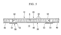
- FIG. 5 is an enlarged view of a major portion of a support guide means 50 according to the first embodiment of the present invention. Further, in FIG. 4 , an inner shell of the liner 12 is not shown, and only an outer shell of the liner 12 is shown as a cross-sectional configuration view. In FIGs. 4 and 5 , in order to improve visibility, the effusion cooling hole 31, the pin 32 and the like are not shown.
- the support guide member 50 configured to support and guide the plate-shaped member 40 having the above-mentioned configuration are installed at the outer wall section 20.
- the support guide member 50 guide the plurality of plate-shaped members 40 to enable insertion and extraction thereof, and support the plurality of plate-shaped members 40 at intervals that can absorb deformation thereof due to thermal expansion.
- the support guide member 50 has a rail member 51 configured to guide both end sections of the plate-shaped member 40 in the circumferential direction of the liner 12.
- the rail member 51 of the embodiment extends in a lengthwise direction of the liner 12 (in FIGs. 4 and 5 , a vertical direction with respect to the drawings).
- the plurality of rail members 51 of the embodiment are installed in the circumferential direction of the liner 12 at intervals.
- the support guide member 50 includes a plurality of slots configured to accommodate the plate-shaped members 40 formed by the plurality of rail members 51 in the circumferential direction of the liner 12.
- the plate-shaped member 40 has both end sections guided by the rail member 51 in the circumferential direction of the liner 12, and is able to be freely inserted and extracted in the lengthwise direction of the liner 12 in which the rail member 51 extends.
- the rail member 51 has a guide section 52 configured to guide a side surface of the plate-shaped member 40, and a support section 53 configured to support a bottom surface of the plate-shaped member 40.
- the guide section 52 is joined with the outer wall section 20 through welding or the like, and stood up inward in the radial direction from the outer wall section 20.
- the support section 53 is integrally formed with the guide section 52, and has a hook shape protruding from the guide section 52 in a direction perpendicular to a standing direction of the guide section 52.
- a distance between the support sections 53 opposite to the neighboring rail members 51 is smaller than a width of the plate-shaped member 40.
- the plate-shaped member 40 and the support section 53 come in contact with each other by a pressure difference between the region (the gap) S between the inner wall section 30 and the outer wall section 20, and the combustion region 13.
- the pressure difference is generated by the pressure of the compressed air supplied to the compressed air chamber 10 from the compressor 2.
- a distance between the opposite guide sections 52 of the neighboring rail members 51 is larger than the width of the plate-shaped member 40.
- a distance between the opposite guide sections 52 of the neighboring rail members 51 is set to a distance assumed as the width of the plate-shaped member 40 that thermally expands upon an operation of the combustor 3. The distance is derived based on a temperature to which the plate-shaped member 40 is exposed upon the operation of the combustor 3, a coefficient of line expansion of a material of the plate-shaped member 40, a shape of the plate-shaped member 40, and so on.
- the plate-shaped member 40 is formed of a heat resistant metal material, and specifically, formed of a nickel-based or cobalt-based metal material.
- the plurality of plate-shaped members 40 supported by the support guide member 50 are disposed at positions corresponding to the plurality of fuel supply nozzles 11 disposed in the circumferential direction of the liner 12.
- the plurality of (in the embodiment, 12) fuel supply nozzles 11 are disposed in the circumferential direction of the liner 12 at predetermined intervals.
- the inner wall section 30 is constituted by the plate-shaped members 40 having the same number (in the embodiment, 12) as the fuel supply nozzles 11. That is, the fuel supply nozzles 11 and the plate-shaped members 40 of the embodiment are disposed to correspond to each other one on one.
- the compressed air flowing outside the outer wall section 20 is introduced into the impingement cooling hole 21 by the differential pressure between the inside and the outside of the combustor 3.
- the compressed air introduced into the impingement cooling hole 21 collides with the inner wall section 30 and cools the inner wall section 30 disposed at the combustion region 13.
- the compressed air that collides with the inner wall section 30 flows between the standing pins 32.
- the pins 32 guide the heat input from the inner surface 30a exposed to the high temperature into the gap S through heat transfer.
- the pins 32 increase the heat-releasing area of the inner wall section 30 in the gap S and increase the cooling efficiency by the compressed air flowing through the gap S.
- Some of the compressed air flowing between the pins 32 is introduced into the effusion cooling hole 31 by the pressure difference between the gap S and the combustion region 13.
- the compressed air introduced into the effusion cooling hole 31 takes the heat of the inner wall section 30 to be discharged to the combustion region 13 in a process of passing a long path inclined with respect to the lengthwise direction of the liner 12. Then, the compressed air discharged to the combustion region 13 flows along the inner surface 30a of the inner wall section 30 to form an inflated structure, and reduces heat input transferred to the inner wall section 30 from the combustion region 13.
- the inner wall section 30 of the embodiment has a split structure, and thus maintainability is superior.
- each of the plurality of plate-shaped members 40 that form the inner wall section 30 is supported by the support guide member 50 installed at the outer wall section 20.
- the support guide member 50 has the rail member 51 configured to guide both end sections of the plate-shaped member 40 in the circumferential direction of the liner 12, and the plate-shaped member 40 can be inserted or extracted in a direction in which the rail member 51 extends.
- the rail member 51 of the embodiment can easily extract the plate-shaped member 40 in the lengthwise direction of the liner 12, except for a retainer 19 extending in the lengthwise direction of the liner 12 and serving as a holder. Accordingly, when the specific plate-shaped member 40 is damaged due to generation of cracks or the like, only the damaged plate-shaped member 40 can be selectively extracted to perform exchange, maintenance or the like.
- the support guide member 50 supports the plurality of plate-shaped members 40 at intervals such that deformation of the plate-shaped members 40 by the thermal expansion can be absorbed.
- the plate-shaped member 40 is not joined with the rail member 51, and the guide sections 52 are disposed at intervals in consideration of the width of the plate-shaped member 40 that thermally expands upon the operation of the combustor 3. For this reason, deformation of the plate-shaped member 40 caused along with the thermal expansion is not physically inhibited, and excessive thermal stress is not generated.
- the inner wall section 30 of the embodiment has superior thermal durability.
- the plurality of fuel supply nozzles 11 configured to supply the fuel to the combustion region 13 are disposed in the circumferential direction of the liner 12 at intervals, and the plurality of plate-shaped members 40 supported by the support guide member 50 are disposed at positions corresponding to the plurality of fuel supply nozzles 11 disposed in the circumferential direction of the liner 12.
- combustion occurs according to the position at which the fuel supply nozzle 11 is disposed, and thus temperature distribution is achieved in the circumferential direction of the liner 12.
- thermal expansion of the plate-shaped members 40 can be substantially uniformized without a bias.
- the inner wall section 30 is constituted by the plurality of plate-shaped members 40, and has the support guide member 50 configured to guide each of the plurality of plate-shaped members 40 to enable free insertion and extraction and configured to support the plurality of plate-shaped members 40 at intervals such that deformation by the thermal expansion can be absorbed.
- the support guide member 50 supports the plurality of plate-shaped members 40 at intervals such that deformation of the plate-shaped members 40 by the thermal expansion can be absorbed. Accordingly, each of the plate-shaped members 40 can easily thermally expand, and generation of excessive thermal stress can be suppressed.
- the liner 12 of the combustor 3 having high maintainability and thermal durability can be obtained.
- FIG. 6 is a configuration of a combustor 3 according to the second embodiment of the present invention.
- the second embodiment is distinguished from the above-mentioned first embodiment in that the rail member 51 of the support guide member 50 extends in the circumferential direction of the liner 12. That is, in the second embodiment, the plate-shaped member 40 is guided in the circumferential direction of the liner 12 to enable free insertion and extraction.
- the configuration of the liner 12 is distinguished in that the base end side of the liner 12 to which the fuel supply nozzle 11 is connected and the distal end side of the liner 12 opposite thereto.
- a positioning member 60 is installed at the distal end side of the liner 12.
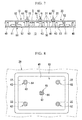
- FIG. 7 is a configuration view of the positioning member 60 according to the second embodiment of the present invention.
- the positioning member 60 positions the plate-shaped member 40 supported by the support guide member 50 with respect to the outer wall section 20.
- the plate-shaped member 40 is pushed to the support section 53 by the pressure difference between the gap S and the combustion region 13, and the clearance between the two walls of the inner wall section 30 and the outer wall section 20 is maintained.
- a size, a shape, or the like, of the plate-shaped member 40 should be designed to prevent the above-mentioned situation.
- the plate-shaped member 40 is positioned with respect to the outer wall section 20 by the positioning member 60 and the clearance of the dual wall is constantly defined. Accordingly, as the clearance of the dual wall is easily managed, and design of a shape or the like of the plate-shaped member 40 in consideration of the cooling efficiency also becomes easy.
- the positioning member 60 has a fixing member 61 configured to hold a distance between the plate-shaped member 40 and the outer wall section 20 and fixed with respect to the outer wall section 20, and a movable member 62 configured to hold a distance between the plate-shaped member 40 and the outer wall section 20 and movable with respect to the outer wall section 20 in thermal expansion of the plate-shaped member 40.
- Each of the fixing member 61 and the movable member 62 has a screw 63 installed at the plate-shaped member 40 and a nut 64 threadedly engaged with the screw 63.
- the screw 63 is formed at the plate-shaped member 40 by cutting from the plate-shaped member 40, or by welding or fitting to the plate-shaped member 40 as a separate article.
- the screw 63 of the fixing member 61 is fastened and fixed to the outer wall section 20 by the nuts 64 disposed at the inside and the outside of the outer wall section 20. That is, the screw 63 of the fixing member 61 cannot be moved relative to the outer wall section 20 in any direction.
- the screw 63 of the movable member 62 is inserted through the hole section 22 of the outer wall section 20 having a larger diameter than that of the screw 63 and threadedly engaged with the nut 64 disposed at the outside of the outer wall section 20. That is, the screw 63 of the movable member 62 can be moved relative to the outer wall section 20 at least in a surface direction parallel to the plate-shaped member 40.
- FIG. 8 is a plan view showing disposition of the fixing member 61 and the movable member 62 according to the second embodiment of the present invention.
- one fixing member 61 is disposed at a central position of the plate-shaped member 40, and four movable members 62 are disposed around the central position of the plate-shaped member 40 at substantially equal intervals.
- thermal expansion of the plate-shaped member 40 is generated about the fixing member 61.
- the distance between the outer wall section 20 and the plate-shaped member 40 can be held by the fixing member 61 and the movable member 62. Even when the plate-shaped member 40 thermally expands about the fixing member 61, since the movable member 62 is movable relative to the outer wall section 20 at least in a surface direction parallel to the plate-shaped member 40 according to the thermal expansion, thermal expansion of the plate-shaped member 40 is not inhibited by the positioning.
- the positioning means 60 having the above-mentioned configuration when the positioning means 60 having the above-mentioned configuration is formed, management of the clearance between the two walls of the inner wall section 30 and the outer wall section 20 becomes easy and the fixed point is generated. For this reason, the configuration of the above-mentioned first embodiment is relatively advantageous in thermal durability.
- the same configuration as in the first embodiment is employed, and in the distal end side of the liner 12 having a lower temperature than that of the base end side of the liner 12, the positioning member 60 is employed. Accordingly, the liner 12 having an effective structure corresponding to the temperature distribution can be provided.
- the positioning member 60 is constituted by the fixing member 61 and the movable member 62
- the present invention is not limited to this configuration.
- the positioning member 60 may be constituted by only the movable member 62.
- the number or disposition of the movable member 62 of the embodiment is also exemplary, and the present invention is not limited to the number or disposition.
- the number of movable members 62 may be one or five or more.
- the movable members 62 may not be disposed at equal intervals.
- each of the fixing member 61 and the movable member 62 is configured by assembling the screw 63, the nut 64, and so on
- the present invention is not limited to this configuration.
- a configuration in which the pin and the flange are assembled may be provided.
- the present invention is applied to the combustor of the gas turbine
- the present invention can also be applied to another combustor, for example, an afterburner of a jet engine or the like.
Landscapes
- Engineering & Computer Science (AREA)
- Chemical & Material Sciences (AREA)
- Combustion & Propulsion (AREA)
- Mechanical Engineering (AREA)
- General Engineering & Computer Science (AREA)
- Ceramic Engineering (AREA)
- Turbine Rotor Nozzle Sealing (AREA)
- Gas Burners (AREA)
Applications Claiming Priority (2)
| Application Number | Priority Date | Filing Date | Title |
|---|---|---|---|
| JP2011246602A JP5821550B2 (ja) | 2011-11-10 | 2011-11-10 | 燃焼器ライナ |
| PCT/JP2012/078733 WO2013069637A1 (fr) | 2011-11-10 | 2012-11-06 | Chemise de chambre de combustion |
Publications (3)
| Publication Number | Publication Date |
|---|---|
| EP2778532A1 true EP2778532A1 (fr) | 2014-09-17 |
| EP2778532A4 EP2778532A4 (fr) | 2015-07-08 |
| EP2778532B1 EP2778532B1 (fr) | 2018-09-05 |
Family
ID=48290011
Family Applications (1)
| Application Number | Title | Priority Date | Filing Date |
|---|---|---|---|
| EP12846946.7A Active EP2778532B1 (fr) | 2011-11-10 | 2012-11-06 | Chemise de chambre de combustion |
Country Status (5)
| Country | Link |
|---|---|
| US (2) | US20140238031A1 (fr) |
| EP (1) | EP2778532B1 (fr) |
| JP (1) | JP5821550B2 (fr) |
| CA (1) | CA2854708C (fr) |
| WO (1) | WO2013069637A1 (fr) |
Cited By (6)
| Publication number | Priority date | Publication date | Assignee | Title |
|---|---|---|---|---|
| WO2013165672A1 (fr) | 2012-05-01 | 2013-11-07 | United Technologies Corporation | Procédé d'actionnement de panneaux de paroi flottante de chambre de combustion |
| EP2792850A4 (fr) * | 2011-12-15 | 2015-10-28 | Ihi Corp | Mécanisme de refroidissement par impact de jet, aube de turbine et chambre de combustion |
| EP3032175A1 (fr) * | 2014-12-12 | 2016-06-15 | United Technologies Corporation | Ensemble paroi refroidi destiné à une chambre de combustion et procédé de conception |
| EP3130853A1 (fr) * | 2015-08-13 | 2017-02-15 | Rolls-Royce plc | Chambre de combustion et segment de chambre de combustion |
| EP3640544A1 (fr) * | 2018-10-15 | 2020-04-22 | United Technologies Corporation | Ensemble de fixation de chemise de chambre de combustion pour moteur à turbine à gaz |
| US11255547B2 (en) | 2018-10-15 | 2022-02-22 | Raytheon Technologies Corporation | Combustor liner attachment assembly for gas turbine engine |
Families Citing this family (16)
| Publication number | Priority date | Publication date | Assignee | Title |
|---|---|---|---|---|
| WO2015039074A1 (fr) | 2013-09-16 | 2015-03-19 | United Technologies Corporation | Variation contrôlée de la chute de pression par refroidissement par effusion dans une chambre de combustion à double paroi d'une turbine à gaz |
| CN104359124A (zh) * | 2014-09-19 | 2015-02-18 | 北京华清燃气轮机与煤气化联合循环工程技术有限公司 | 一种燃气轮机燃烧室的导流衬套 |
| GB201501817D0 (en) * | 2015-02-04 | 2015-03-18 | Rolls Royce Plc | A combustion chamber and a combustion chamber segment |
| US10634349B2 (en) * | 2015-08-24 | 2020-04-28 | General Electric Company | Wear pad system for turbine combustion systems and method for coupling wear pad into turbine combustion system |
| US10260751B2 (en) * | 2015-09-28 | 2019-04-16 | Pratt & Whitney Canada Corp. | Single skin combustor with heat transfer enhancement |
| US10876730B2 (en) | 2016-02-25 | 2020-12-29 | Pratt & Whitney Canada Corp. | Combustor primary zone cooling flow scheme |
| US10443846B2 (en) * | 2016-04-21 | 2019-10-15 | United Technologies Corporation | Combustor thermal shield fabrication method |
| KR101983469B1 (ko) * | 2017-10-20 | 2019-09-10 | 두산중공업 주식회사 | 터빈 블레이드 링 세그멘트 및 이를 포함하는 터빈 및 가스터빈 |
| US10928067B2 (en) | 2017-10-31 | 2021-02-23 | Pratt & Whitney Canada Corp. | Double skin combustor |
| FR3118658B1 (fr) * | 2021-01-04 | 2024-01-26 | Safran Helicopter Engines | Double paroi pour chambre de combustion de turbine à gaz d’aéronef et procédé de fabrication d’une telle double paroi |
| JP7614980B2 (ja) | 2021-08-25 | 2025-01-16 | 三菱重工航空エンジン株式会社 | 燃焼器パネル、及びガスタービン用燃焼器 |
| CN114151227B (zh) * | 2021-10-20 | 2023-05-05 | 中国航发四川燃气涡轮研究院 | 一种用于二元矢量喷管的隔热屏结构 |
| JP7854294B2 (ja) * | 2021-12-27 | 2026-05-01 | 川崎重工業株式会社 | ガスタービンの燃焼器 |
| CN116697401B (zh) | 2022-02-24 | 2025-12-12 | 通用电气公司 | 具有用于局部衬套冷却的冷却分散构件的燃烧器衬套 |
| JP2024043164A (ja) | 2022-09-16 | 2024-03-29 | 三菱重工航空エンジン株式会社 | 熱交換隔壁 |
| JP2024091028A (ja) * | 2022-12-23 | 2024-07-04 | 川崎重工業株式会社 | ガスタービンの燃焼器 |
Family Cites Families (26)
| Publication number | Priority date | Publication date | Assignee | Title |
|---|---|---|---|---|
| US2544538A (en) * | 1948-12-01 | 1951-03-06 | Wright Aeronautical Corp | Liner for hot gas chambers |
| US4555901A (en) * | 1972-12-19 | 1985-12-03 | General Electric Company | Combustion chamber construction |
| US4614082A (en) * | 1972-12-19 | 1986-09-30 | General Electric Company | Combustion chamber construction |
| US4480436A (en) * | 1972-12-19 | 1984-11-06 | General Electric Company | Combustion chamber construction |
| US3956886A (en) * | 1973-12-07 | 1976-05-18 | Joseph Lucas (Industries) Limited | Flame tubes for gas turbine engines |
| US4158949A (en) * | 1977-11-25 | 1979-06-26 | General Motors Corporation | Segmented annular combustor |
| JPS57124620A (en) * | 1981-01-23 | 1982-08-03 | Toshiba Corp | Combustor |
| US4567730A (en) * | 1983-10-03 | 1986-02-04 | General Electric Company | Shielded combustor |
| US4688310A (en) * | 1983-12-19 | 1987-08-25 | General Electric Company | Fabricated liner article and method |
| DE3519938A1 (de) * | 1985-06-04 | 1986-12-04 | MTU Motoren- und Turbinen-Union München GmbH, 8000 München | Brennkammereinrichtung |
| FR2599821B1 (fr) * | 1986-06-04 | 1988-09-02 | Snecma | Chambre de combustion pour turbomachines a orifices de melange assurant le positionnement de la paroi chaude sur la paroi froide |
| FR2624953B1 (fr) * | 1987-12-16 | 1990-04-20 | Snecma | Chambre de combustion, pour turbomachines, possedant un convergent a doubles parois |
| GB9106085D0 (en) | 1991-03-22 | 1991-05-08 | Rolls Royce Plc | Gas turbine engine combustor |
| CA2100319C (fr) | 1992-08-31 | 2003-10-07 | Michael J. Deaner | Element de structure perfectionne en composite polymere/bois |
| FR2710968B1 (fr) * | 1993-10-06 | 1995-11-03 | Snecma | Chambre de combustion à double paroi. |
| FR2723177B1 (fr) * | 1994-07-27 | 1996-09-06 | Snecma | Chambre de combustion comportant une double paroi |
| JP3488902B2 (ja) | 1995-03-16 | 2004-01-19 | 川崎重工業株式会社 | ガスタービン燃焼器の冷却方法および冷却構造 |
| GB2356924A (en) * | 1999-12-01 | 2001-06-06 | Abb Alstom Power Uk Ltd | Cooling wall structure for combustor |
| US6702549B2 (en) * | 2000-03-02 | 2004-03-09 | Siemens Aktiengesellschaft | Turbine installation |
| GB2368902A (en) * | 2000-11-11 | 2002-05-15 | Rolls Royce Plc | A double wall combustor arrangement |
| US7003774B2 (en) * | 2001-07-16 | 2006-02-21 | Smartmatic | Multidimensional advanced adaptive software architecture |
| EP1288578A1 (fr) * | 2001-08-31 | 2003-03-05 | Siemens Aktiengesellschaft | Agencement de chambre de combustion |
| GB2384046B (en) * | 2002-01-15 | 2005-07-06 | Rolls Royce Plc | A double wall combuster tile arrangement |
| US7146815B2 (en) * | 2003-07-31 | 2006-12-12 | United Technologies Corporation | Combustor |
| DE102007018061A1 (de) * | 2007-04-17 | 2008-10-23 | Rolls-Royce Deutschland Ltd & Co Kg | Gasturbinenbrennkammerwand |
| US20100037620A1 (en) * | 2008-08-15 | 2010-02-18 | General Electric Company, Schenectady | Impingement and effusion cooled combustor component |
-
2011
- 2011-11-10 JP JP2011246602A patent/JP5821550B2/ja active Active
-
2012
- 2012-11-06 WO PCT/JP2012/078733 patent/WO2013069637A1/fr not_active Ceased
- 2012-11-06 CA CA2854708A patent/CA2854708C/fr active Active
- 2012-11-06 EP EP12846946.7A patent/EP2778532B1/fr active Active
-
2014
- 2014-05-06 US US14/270,811 patent/US20140238031A1/en not_active Abandoned
-
2017
- 2017-08-09 US US15/672,435 patent/US10551067B2/en active Active
Cited By (10)
| Publication number | Priority date | Publication date | Assignee | Title |
|---|---|---|---|---|
| EP2792850A4 (fr) * | 2011-12-15 | 2015-10-28 | Ihi Corp | Mécanisme de refroidissement par impact de jet, aube de turbine et chambre de combustion |
| US9957812B2 (en) | 2011-12-15 | 2018-05-01 | Ihi Corporation | Impingement cooling mechanism, turbine blade and cumbustor |
| WO2013165672A1 (fr) | 2012-05-01 | 2013-11-07 | United Technologies Corporation | Procédé d'actionnement de panneaux de paroi flottante de chambre de combustion |
| EP2844423A4 (fr) * | 2012-05-01 | 2015-05-06 | United Technologies Corp | Procédé d'actionnement de panneaux de paroi flottante de chambre de combustion |
| EP3032175A1 (fr) * | 2014-12-12 | 2016-06-15 | United Technologies Corporation | Ensemble paroi refroidi destiné à une chambre de combustion et procédé de conception |
| EP3130853A1 (fr) * | 2015-08-13 | 2017-02-15 | Rolls-Royce plc | Chambre de combustion et segment de chambre de combustion |
| US10634350B2 (en) | 2015-08-13 | 2020-04-28 | Rolls-Royce Plc | Combustion chamber and a combustion chamber segment |
| EP3640544A1 (fr) * | 2018-10-15 | 2020-04-22 | United Technologies Corporation | Ensemble de fixation de chemise de chambre de combustion pour moteur à turbine à gaz |
| US11255547B2 (en) | 2018-10-15 | 2022-02-22 | Raytheon Technologies Corporation | Combustor liner attachment assembly for gas turbine engine |
| US11293637B2 (en) | 2018-10-15 | 2022-04-05 | Raytheon Technologies Corporation | Combustor liner attachment assembly for gas turbine engine |
Also Published As
| Publication number | Publication date |
|---|---|
| EP2778532A4 (fr) | 2015-07-08 |
| CA2854708C (fr) | 2016-08-09 |
| US20170370586A1 (en) | 2017-12-28 |
| JP5821550B2 (ja) | 2015-11-24 |
| JP2013104307A (ja) | 2013-05-30 |
| EP2778532B1 (fr) | 2018-09-05 |
| US20140238031A1 (en) | 2014-08-28 |
| CA2854708A1 (fr) | 2013-05-16 |
| US10551067B2 (en) | 2020-02-04 |
| WO2013069637A1 (fr) | 2013-05-16 |
Similar Documents
| Publication | Publication Date | Title |
|---|---|---|
| US10551067B2 (en) | Combustor liner with dual wall cooling structure | |
| EP2378200B1 (fr) | Refroidissement de chemise de chambre de combustion sur une interface de conduite de transition et procédé associé | |
| US9464538B2 (en) | Shroud block segment for a gas turbine | |
| CN105804806B (zh) | 用于燃烧器涡轮界面的框架节段 | |
| US10145559B2 (en) | Gas turbine engine with igniter stack or borescope mount having noncollinear cooling passages | |
| US10436445B2 (en) | Assembly for controlling clearance between a liner and stationary nozzle within a gas turbine | |
| JP6324548B2 (ja) | 排気ディフューザ内にロータセンタリング冷却システムを備えるガスタービンエンジン | |
| JP6200170B2 (ja) | ガスタービンを流れる高温ガスを循環させるシステム及び方法 | |
| EP2162598B1 (fr) | Système de refroidissement d'aube de turbine doté d'un refroidissement de rotor par impact | |
| JP2010043643A (ja) | インピンジメント及びエフュージョン冷却式燃焼器部品 | |
| EP2489937B1 (fr) | Ensemble de chambre de combustion pour un moteur de turbine et son procédé de fabrication | |
| JP2014009937A (ja) | ガスタービン用移行ダクト | |
| JP5679246B1 (ja) | ガスタービンの高温部品、これを備えるガスタービン、及びガスタービンの高温部品の製造方法 | |
| EP2634372A1 (fr) | Agencement de cadre arrière de pièce de transition avec bouclier thermique et système associé de combustion | |
| CN107461225B (zh) | 用于燃气涡轮发动机的喷嘴冷却系统 | |
| EP2538028A2 (fr) | Procédés et systèmes de refroidissement d'une conduite de transition | |
| JP2019002397A (ja) | ターボ機械冷却システム | |
| EP3330486B1 (fr) | Insert d'impact pour un moteur à turbine à gaz | |
| US10968776B2 (en) | Turbine support structure | |
| JP5910008B2 (ja) | 燃焼器ライナ | |
| JP2016121679A (ja) | ガスタービントランジションピースの後部フレーム組立体支持部 | |
| JP4235208B2 (ja) | ガスタービンの尾筒構造 | |
| JP5725929B2 (ja) | ガスタービン |
Legal Events
| Date | Code | Title | Description |
|---|---|---|---|
| PUAI | Public reference made under article 153(3) epc to a published international application that has entered the european phase |
Free format text: ORIGINAL CODE: 0009012 |
|
| 17P | Request for examination filed |
Effective date: 20140508 |
|
| AK | Designated contracting states |
Kind code of ref document: A1 Designated state(s): AL AT BE BG CH CY CZ DE DK EE ES FI FR GB GR HR HU IE IS IT LI LT LU LV MC MK MT NL NO PL PT RO RS SE SI SK SM TR |
|
| DAX | Request for extension of the european patent (deleted) | ||
| REG | Reference to a national code |
Ref country code: DE Ref legal event code: R079 Ref document number: 602012050803 Country of ref document: DE Free format text: PREVIOUS MAIN CLASS: F23R0003420000 Ipc: F23R0003000000 |
|
| RA4 | Supplementary search report drawn up and despatched (corrected) |
Effective date: 20150609 |
|
| RIC1 | Information provided on ipc code assigned before grant |
Ipc: F23R 3/42 20060101ALI20150602BHEP Ipc: F23R 3/06 20060101ALI20150602BHEP Ipc: F23R 3/00 20060101AFI20150602BHEP |
|
| GRAP | Despatch of communication of intention to grant a patent |
Free format text: ORIGINAL CODE: EPIDOSNIGR1 |
|
| INTG | Intention to grant announced |
Effective date: 20180430 |
|
| GRAS | Grant fee paid |
Free format text: ORIGINAL CODE: EPIDOSNIGR3 |
|
| GRAA | (expected) grant |
Free format text: ORIGINAL CODE: 0009210 |
|
| AK | Designated contracting states |
Kind code of ref document: B1 Designated state(s): AL AT BE BG CH CY CZ DE DK EE ES FI FR GB GR HR HU IE IS IT LI LT LU LV MC MK MT NL NO PL PT RO RS SE SI SK SM TR |
|
| REG | Reference to a national code |
Ref country code: GB Ref legal event code: FG4D |
|
| REG | Reference to a national code |
Ref country code: CH Ref legal event code: EP |
|
| REG | Reference to a national code |
Ref country code: AT Ref legal event code: REF Ref document number: 1038260 Country of ref document: AT Kind code of ref document: T Effective date: 20180915 |
|
| REG | Reference to a national code |
Ref country code: IE Ref legal event code: FG4D |
|
| REG | Reference to a national code |
Ref country code: DE Ref legal event code: R096 Ref document number: 602012050803 Country of ref document: DE |
|
| REG | Reference to a national code |
Ref country code: FR Ref legal event code: PLFP Year of fee payment: 7 |
|
| REG | Reference to a national code |
Ref country code: NL Ref legal event code: MP Effective date: 20180905 |
|
| REG | Reference to a national code |
Ref country code: LT Ref legal event code: MG4D |
|
| PG25 | Lapsed in a contracting state [announced via postgrant information from national office to epo] |
Ref country code: SE Free format text: LAPSE BECAUSE OF FAILURE TO SUBMIT A TRANSLATION OF THE DESCRIPTION OR TO PAY THE FEE WITHIN THE PRESCRIBED TIME-LIMIT Effective date: 20180905 Ref country code: BG Free format text: LAPSE BECAUSE OF FAILURE TO SUBMIT A TRANSLATION OF THE DESCRIPTION OR TO PAY THE FEE WITHIN THE PRESCRIBED TIME-LIMIT Effective date: 20181205 Ref country code: LT Free format text: LAPSE BECAUSE OF FAILURE TO SUBMIT A TRANSLATION OF THE DESCRIPTION OR TO PAY THE FEE WITHIN THE PRESCRIBED TIME-LIMIT Effective date: 20180905 Ref country code: FI Free format text: LAPSE BECAUSE OF FAILURE TO SUBMIT A TRANSLATION OF THE DESCRIPTION OR TO PAY THE FEE WITHIN THE PRESCRIBED TIME-LIMIT Effective date: 20180905 Ref country code: NO Free format text: LAPSE BECAUSE OF FAILURE TO SUBMIT A TRANSLATION OF THE DESCRIPTION OR TO PAY THE FEE WITHIN THE PRESCRIBED TIME-LIMIT Effective date: 20181205 Ref country code: GR Free format text: LAPSE BECAUSE OF FAILURE TO SUBMIT A TRANSLATION OF THE DESCRIPTION OR TO PAY THE FEE WITHIN THE PRESCRIBED TIME-LIMIT Effective date: 20181206 Ref country code: RS Free format text: LAPSE BECAUSE OF FAILURE TO SUBMIT A TRANSLATION OF THE DESCRIPTION OR TO PAY THE FEE WITHIN THE PRESCRIBED TIME-LIMIT Effective date: 20180905 |
|
| REG | Reference to a national code |
Ref country code: AT Ref legal event code: MK05 Ref document number: 1038260 Country of ref document: AT Kind code of ref document: T Effective date: 20180905 |
|
| PG25 | Lapsed in a contracting state [announced via postgrant information from national office to epo] |
Ref country code: AL Free format text: LAPSE BECAUSE OF FAILURE TO SUBMIT A TRANSLATION OF THE DESCRIPTION OR TO PAY THE FEE WITHIN THE PRESCRIBED TIME-LIMIT Effective date: 20180905 Ref country code: HR Free format text: LAPSE BECAUSE OF FAILURE TO SUBMIT A TRANSLATION OF THE DESCRIPTION OR TO PAY THE FEE WITHIN THE PRESCRIBED TIME-LIMIT Effective date: 20180905 Ref country code: LV Free format text: LAPSE BECAUSE OF FAILURE TO SUBMIT A TRANSLATION OF THE DESCRIPTION OR TO PAY THE FEE WITHIN THE PRESCRIBED TIME-LIMIT Effective date: 20180905 |
|
| PG25 | Lapsed in a contracting state [announced via postgrant information from national office to epo] |
Ref country code: EE Free format text: LAPSE BECAUSE OF FAILURE TO SUBMIT A TRANSLATION OF THE DESCRIPTION OR TO PAY THE FEE WITHIN THE PRESCRIBED TIME-LIMIT Effective date: 20180905 Ref country code: PL Free format text: LAPSE BECAUSE OF FAILURE TO SUBMIT A TRANSLATION OF THE DESCRIPTION OR TO PAY THE FEE WITHIN THE PRESCRIBED TIME-LIMIT Effective date: 20180905 Ref country code: NL Free format text: LAPSE BECAUSE OF FAILURE TO SUBMIT A TRANSLATION OF THE DESCRIPTION OR TO PAY THE FEE WITHIN THE PRESCRIBED TIME-LIMIT Effective date: 20180905 Ref country code: AT Free format text: LAPSE BECAUSE OF FAILURE TO SUBMIT A TRANSLATION OF THE DESCRIPTION OR TO PAY THE FEE WITHIN THE PRESCRIBED TIME-LIMIT Effective date: 20180905 Ref country code: IT Free format text: LAPSE BECAUSE OF FAILURE TO SUBMIT A TRANSLATION OF THE DESCRIPTION OR TO PAY THE FEE WITHIN THE PRESCRIBED TIME-LIMIT Effective date: 20180905 Ref country code: CZ Free format text: LAPSE BECAUSE OF FAILURE TO SUBMIT A TRANSLATION OF THE DESCRIPTION OR TO PAY THE FEE WITHIN THE PRESCRIBED TIME-LIMIT Effective date: 20180905 Ref country code: RO Free format text: LAPSE BECAUSE OF FAILURE TO SUBMIT A TRANSLATION OF THE DESCRIPTION OR TO PAY THE FEE WITHIN THE PRESCRIBED TIME-LIMIT Effective date: 20180905 Ref country code: IS Free format text: LAPSE BECAUSE OF FAILURE TO SUBMIT A TRANSLATION OF THE DESCRIPTION OR TO PAY THE FEE WITHIN THE PRESCRIBED TIME-LIMIT Effective date: 20190105 Ref country code: ES Free format text: LAPSE BECAUSE OF FAILURE TO SUBMIT A TRANSLATION OF THE DESCRIPTION OR TO PAY THE FEE WITHIN THE PRESCRIBED TIME-LIMIT Effective date: 20180905 |
|
| PG25 | Lapsed in a contracting state [announced via postgrant information from national office to epo] |
Ref country code: SK Free format text: LAPSE BECAUSE OF FAILURE TO SUBMIT A TRANSLATION OF THE DESCRIPTION OR TO PAY THE FEE WITHIN THE PRESCRIBED TIME-LIMIT Effective date: 20180905 Ref country code: PT Free format text: LAPSE BECAUSE OF FAILURE TO SUBMIT A TRANSLATION OF THE DESCRIPTION OR TO PAY THE FEE WITHIN THE PRESCRIBED TIME-LIMIT Effective date: 20190105 Ref country code: SM Free format text: LAPSE BECAUSE OF FAILURE TO SUBMIT A TRANSLATION OF THE DESCRIPTION OR TO PAY THE FEE WITHIN THE PRESCRIBED TIME-LIMIT Effective date: 20180905 |
|
| REG | Reference to a national code |
Ref country code: DE Ref legal event code: R097 Ref document number: 602012050803 Country of ref document: DE |
|
| REG | Reference to a national code |
Ref country code: CH Ref legal event code: PL |
|
| PLBE | No opposition filed within time limit |
Free format text: ORIGINAL CODE: 0009261 |
|
| STAA | Information on the status of an ep patent application or granted ep patent |
Free format text: STATUS: NO OPPOSITION FILED WITHIN TIME LIMIT |
|
| PG25 | Lapsed in a contracting state [announced via postgrant information from national office to epo] |
Ref country code: LU Free format text: LAPSE BECAUSE OF NON-PAYMENT OF DUE FEES Effective date: 20181106 Ref country code: MC Free format text: LAPSE BECAUSE OF FAILURE TO SUBMIT A TRANSLATION OF THE DESCRIPTION OR TO PAY THE FEE WITHIN THE PRESCRIBED TIME-LIMIT Effective date: 20180905 Ref country code: DK Free format text: LAPSE BECAUSE OF FAILURE TO SUBMIT A TRANSLATION OF THE DESCRIPTION OR TO PAY THE FEE WITHIN THE PRESCRIBED TIME-LIMIT Effective date: 20180905 |
|
| 26N | No opposition filed |
Effective date: 20190606 |
|
| REG | Reference to a national code |
Ref country code: BE Ref legal event code: MM Effective date: 20181130 |
|
| REG | Reference to a national code |
Ref country code: IE Ref legal event code: MM4A |
|
| PG25 | Lapsed in a contracting state [announced via postgrant information from national office to epo] |
Ref country code: LI Free format text: LAPSE BECAUSE OF NON-PAYMENT OF DUE FEES Effective date: 20181130 Ref country code: SI Free format text: LAPSE BECAUSE OF FAILURE TO SUBMIT A TRANSLATION OF THE DESCRIPTION OR TO PAY THE FEE WITHIN THE PRESCRIBED TIME-LIMIT Effective date: 20180905 Ref country code: CH Free format text: LAPSE BECAUSE OF NON-PAYMENT OF DUE FEES Effective date: 20181130 |
|
| PG25 | Lapsed in a contracting state [announced via postgrant information from national office to epo] |
Ref country code: IE Free format text: LAPSE BECAUSE OF NON-PAYMENT OF DUE FEES Effective date: 20181106 |
|
| PG25 | Lapsed in a contracting state [announced via postgrant information from national office to epo] |
Ref country code: BE Free format text: LAPSE BECAUSE OF NON-PAYMENT OF DUE FEES Effective date: 20181130 |
|
| PG25 | Lapsed in a contracting state [announced via postgrant information from national office to epo] |
Ref country code: MT Free format text: LAPSE BECAUSE OF NON-PAYMENT OF DUE FEES Effective date: 20181106 |
|
| PG25 | Lapsed in a contracting state [announced via postgrant information from national office to epo] |
Ref country code: TR Free format text: LAPSE BECAUSE OF FAILURE TO SUBMIT A TRANSLATION OF THE DESCRIPTION OR TO PAY THE FEE WITHIN THE PRESCRIBED TIME-LIMIT Effective date: 20180905 |
|
| PG25 | Lapsed in a contracting state [announced via postgrant information from national office to epo] |
Ref country code: CY Free format text: LAPSE BECAUSE OF FAILURE TO SUBMIT A TRANSLATION OF THE DESCRIPTION OR TO PAY THE FEE WITHIN THE PRESCRIBED TIME-LIMIT Effective date: 20180905 Ref country code: MK Free format text: LAPSE BECAUSE OF NON-PAYMENT OF DUE FEES Effective date: 20180905 Ref country code: HU Free format text: LAPSE BECAUSE OF FAILURE TO SUBMIT A TRANSLATION OF THE DESCRIPTION OR TO PAY THE FEE WITHIN THE PRESCRIBED TIME-LIMIT; INVALID AB INITIO Effective date: 20121106 |
|
| PGFP | Annual fee paid to national office [announced via postgrant information from national office to epo] |
Ref country code: DE Payment date: 20251022 Year of fee payment: 14 |
|
| PGFP | Annual fee paid to national office [announced via postgrant information from national office to epo] |
Ref country code: GB Payment date: 20251023 Year of fee payment: 14 |
|
| PGFP | Annual fee paid to national office [announced via postgrant information from national office to epo] |
Ref country code: FR Payment date: 20251023 Year of fee payment: 14 |