EP2778535A2 - Dispositif de récupération de chaleur pour conduit de fumée - Google Patents
Dispositif de récupération de chaleur pour conduit de fumée Download PDFInfo
- Publication number
- EP2778535A2 EP2778535A2 EP14159831.8A EP14159831A EP2778535A2 EP 2778535 A2 EP2778535 A2 EP 2778535A2 EP 14159831 A EP14159831 A EP 14159831A EP 2778535 A2 EP2778535 A2 EP 2778535A2
- Authority
- EP
- European Patent Office
- Prior art keywords
- heat recovery
- chimney
- pipe
- water space
- flue
- Prior art date
- Legal status (The legal status is an assumption and is not a legal conclusion. Google has not performed a legal analysis and makes no representation as to the accuracy of the status listed.)
- Withdrawn
Links
- 238000011084 recovery Methods 0.000 title claims abstract description 76
- XLYOFNOQVPJJNP-UHFFFAOYSA-N water Substances O XLYOFNOQVPJJNP-UHFFFAOYSA-N 0.000 claims abstract description 74
- 230000008878 coupling Effects 0.000 claims abstract description 29
- 238000010168 coupling process Methods 0.000 claims abstract description 29
- 238000005859 coupling reaction Methods 0.000 claims abstract description 29
- 239000012530 fluid Substances 0.000 claims abstract description 20
- 239000003546 flue gas Substances 0.000 claims abstract description 8
- UGFAIRIUMAVXCW-UHFFFAOYSA-N Carbon monoxide Chemical compound [O+]#[C-] UGFAIRIUMAVXCW-UHFFFAOYSA-N 0.000 claims abstract description 4
- 238000009413 insulation Methods 0.000 claims description 9
- 238000013022 venting Methods 0.000 claims description 7
- 238000010438 heat treatment Methods 0.000 description 4
- 238000003466 welding Methods 0.000 description 4
- 239000000463 material Substances 0.000 description 2
- 230000002787 reinforcement Effects 0.000 description 2
- 229910000831 Steel Inorganic materials 0.000 description 1
- 239000000919 ceramic Substances 0.000 description 1
- 230000008602 contraction Effects 0.000 description 1
- 239000008236 heating water Substances 0.000 description 1
- 238000009434 installation Methods 0.000 description 1
- 238000004519 manufacturing process Methods 0.000 description 1
- 239000010959 steel Substances 0.000 description 1
- 239000008400 supply water Substances 0.000 description 1
- 239000002918 waste heat Substances 0.000 description 1
Images


Classifications
-
- F—MECHANICAL ENGINEERING; LIGHTING; HEATING; WEAPONS; BLASTING
- F24—HEATING; RANGES; VENTILATING
- F24B—DOMESTIC STOVES OR RANGES FOR SOLID FUELS; IMPLEMENTS FOR USE IN CONNECTION WITH STOVES OR RANGES
- F24B9/00—Stoves, ranges or flue-gas ducts, with additional provisions for heating water
- F24B9/006—Stoves, ranges or flue-gas ducts, with additional provisions for heating water flue-gas ducts
-
- F—MECHANICAL ENGINEERING; LIGHTING; HEATING; WEAPONS; BLASTING
- F24—HEATING; RANGES; VENTILATING
- F24B—DOMESTIC STOVES OR RANGES FOR SOLID FUELS; IMPLEMENTS FOR USE IN CONNECTION WITH STOVES OR RANGES
- F24B1/00—Stoves or ranges
- F24B1/18—Stoves with open fires, e.g. fireplaces
- F24B1/183—Stoves with open fires, e.g. fireplaces with additional provisions for heating water
-
- F—MECHANICAL ENGINEERING; LIGHTING; HEATING; WEAPONS; BLASTING
- F28—HEAT EXCHANGE IN GENERAL
- F28D—HEAT-EXCHANGE APPARATUS, NOT PROVIDED FOR IN ANOTHER SUBCLASS, IN WHICH THE HEAT-EXCHANGE MEDIA DO NOT COME INTO DIRECT CONTACT
- F28D21/00—Heat-exchange apparatus not covered by any of the groups F28D1/00 - F28D20/00
- F28D21/0001—Recuperative heat exchangers
- F28D21/0003—Recuperative heat exchangers the heat being recuperated from exhaust gases
- F28D21/0005—Recuperative heat exchangers the heat being recuperated from exhaust gases for domestic or space-heating systems
Definitions
- the invention relates to a heat recovery chimney comprising a flue pipe for connection to a fireplace and a jacket pipe fitted around the flue pipe so that the flue pipe and the jacket pipe delimit an annular water space closed by end pieces at both ends in the direction of the length of the heat recovery chimney to form a closed space, in which water space heat-storing fluid is circulated and receives heat produced by flue gas directly from the flue pipe, from which fluid the heat is arranged to be utilized.
- Heat recovery chimneys per se are known in the prior art.
- a container space is formed around the flue pipe by means of a jacket pipe and is thus delimited from the inside by the flue pipe and from the outside by said jacket pipe.
- Fluid preferably water
- a container space is formed around the flue pipe by means of a jacket pipe and is thus delimited from the inside by the flue pipe and from the outside by said jacket pipe.
- Fluid preferably water
- one or more heat exchangers may be provided in the container space. Heat from flue gases is transferred from the flue pipe directly to the fluid in the container space and further through the optional heat exchanger to the heat exchange circuit thereof.
- Fluid from the container space may also be circulated directly for example to the heat-releasing element of radiator or floor heating.
- the flue pipe is connected to a fireplace, e.g. a heat-storing fireplace or a wood-heated sauna stove.
- a fireplace e.g. a heat-storing fireplace or a wood-heated sauna stove.
- the jacket pipe that surrounds the container space is further provided with an external thermal insulation.
- the structure encompasses the problem that the pipes connected to the container space for circulating water in the container space, i.e. the circulation water pipes of the heat recovery chimney, are connected to the container space so that the pipes that supply water to the container space and convey it out therefrom are connected at the different ends of the chimney.
- the circulation water pipes generally the pipe that supplies water to the container space
- the other circulation water pipe must be laid from outside the chimney. This has been disadvantageous e.g. because a groove must be made in the insulation of the chimney for the pipe, or the piping has been made entirely outside the chimney. This has restricted the installation of the chimney and making of the pipe connections.
- the objective of the present invention is to provide a new and improved heat recovery chimney.
- the invention is mainly characterized in that a flow channel is fitted inside the water space of the heat recovery chimney and extends substantially from the bottom end of the water space to the top end thereof, to one end of which flow channel an inlet coupling is connected to supply circulation fluid to the flow channel and through the opposite open end of which flow channel the circulated fluid is discharged into the water space from which it is reclaimed through a fluid outlet coupling connected to the jacket pipe at the same end of the water space in the direction of the length of the heat recovery chimney as the inlet coupling.
- the water space is suitably provided with a venting channel which is connected to the jacket pipe at the same end of the heat recovery chimney as the circulation fluid inlet coupling and outlet coupling, wherefrom the venting channel extends as a narrow pipe or a suchlike channel inside the water space alongside the flow channel to the opposite end of the water space.
- All pipe connections of the heat recovery chimney are most preferably provided at the same end of the heat recovery chimney.
- the depth of the flow channel according to the invention i.e. the dimension in the radial direction of the heat recovery chimney, is substantially smaller than the width of the flow channel, i.e. the dimension in the circumferential direction of the heat recovery chimney.
- Support flanges are fitted in the water space of the heat recovery chimney at a distance from one another in the direction of the length of the heat recovery chimney and for the most part surround the flue pipe mainly in the transverse direction of the heat recovery chimney.
- the support flanges are truncated flanges, so that gaps are provided between the truncated ends of the support flanges and the flow channel to allow the circulation of water in the water space.
- the heat recovery chimney is provided with an insulation fitted over the jacket pipe.
- the heat recovery chimney is preferably arranged to operate as an insert of a block flue, i.e. a flue made of flue blocks.
- the invention provides significant advantages as compared to the prior art. All water couplings of the heat recovery chimney according to the invention can be made at the same end of the heat recovery part of the chimney.
- the solution according to the invention allows an unbroken jacket structure so that the heat recovery part of the chimney can be installed inside a standard chimney structure without breaking the insulation.
- the structure can be utilized e.g. by installing the chimney according to the invention e.g. to a block chimney, into a hole in the blocks.
- the water circulation required for the heat recovery chimney can be provided inside the water space of the heat recovery part where space is very limited.
- the invention also allows the arrangement of the heat recovery structure to the side of the attic space. All pipe connections of the chimney can be made at the bottom end or the top end of the chimney, which provides significant cost savings in the pipe work.
- venting of the water space may be provided through the bottom end of the chimney, which also brings cost savings to the pipe work. Vent piping or air separators are not required at the top end of the heat recovery part.
- the jacket pipe that delimits the water space from the outside and the flue pipe that delimits it from the inside are coupled to each other in a way that allows the thermal expansion of the flue pipe without stress on the welded seams or the flue pipe.
- this is provided by new types of end pieces of the top and bottom end of the heat recovery chimney shaped so that they function as end and flexible elements.
- Fig. 1 shows a general view of the heat recovery chimney according to the invention as seen from the side.
- the heat recovery chimney is indicated generally in Fig. 1 by the reference number 10.
- the heat recovery chimney 10 is also referred to as a "chimney" in the description below.
- the structures of the chimney 10 are more clearly visible in the figures that illustrate the details of the chimney.
- the chimney 10 comprises a flue pipe 11 for connection to a fireplace (not illustrated), e.g. a heat-storing fireplace or a wood-heated sauna stove.
- a jacket pipe 12 is fitted around the flue pipe 11 so that the flue pipe 11 and the jacket pipe 12 delimit an annular container space, i.e. a water space 21 of the chimney 10 (not illustrated in Fig. 1 ).
- the top and bottom ends of the water space 21 are further closed by end pieces 16.
- Fig. 1 shows in dashed lines that a flow channel 13 is fitted in the water space 21 of the chimney 10 for circulating water in the solution of Fig. 1 from the bottom end to the top end of the water space 21, where the water is discharged from the flow channel 13 to the water space 21 so as to flow back down.
- the circulation water is conveyed to the flow channel 13 through an inlet coupling 17 at the bottom end thereof and out of the water space 21 through an outlet coupling 18, both of which couplings 17, 18 are disposed at the same end of the chimney 10, namely at the bottom end in Fig. 1 .
- a venting channel 19 and a sensor coupling 20 are provided at the same end of the chimney 10 as the circulation water inlet and outlet couplings 17, 18, so that all pipe connections are made, or can be made, in the area of the same end of the chimney 10.
- a grooving 14 may be formed in the area of the top end of the jacket pipe 12, as illustrated in Fig. 1 , for receiving the expansions and contractions caused by thermal expansion of the flue pipe 11 in the jacket pipe 12.
- this may also be catered for in other ways, e.g. as disclosed in an earlier registered Finnish utility model No. 8495 from the applicant. Other practices are also possible.
- Fig. 1 shows that a base plate 15 is provided in the area of the bottom end of the chimney 10 below the water space 21.
- the jacket pipe 12 that surrounds the water space 21 is further provided with an external thermal insulation to be able to recover the heat effectively.
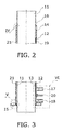
- the structures of the heat recovery chimney 10, the water space 21 of the chimney and the flow channel 13 fitted in the water space are illustrated in more detail in Fig. 2 - 10 . Accordingly, as illustrated in Fig. 2 and 4 and as already stated above, the top end of the water space 21 is closed by an end piece 16.
- the end piece 16 is shaped so that it flexibly connects the flue pipe 11 to the jacket pipe 12 so as to allow the thermal expansion of the flue pipe 11 without stress on the welded seams or the flue pipe 11.
- another such flexible end piece 16 is also fitted at the bottom end of the water space 21 to close the water space 21 and to flexibly connect the flue pipe 11 and the jacket pipe 12 to each other.
- the pipe connections of the chimney 10 are illustrated in more detail in Fig. 3 and 6 .
- the inlet coupling 17 is connected to the flow channel 13 and the outlet coupling 18 to the jacket pipe 12.
- the sensor coupling 20 is connected to the jacket pipe 12 and, as shown in particular in Fig. 6 , it is to be noted in that connection that the end of the sleeve of the sensor coupling 20 does not extend inside the jacket pipe 12 to such a degree that it would contact the flue pipe 11.
- the venting channel 19 is connected to the jacket pipe 12 at the bottom end of the chimney 10 and extends as a narrow pipe inside the water space 21 alongside the flow channel 13 to the top end of the water space 21.
- the heat recovery chimney 10 further comprises support flanges 26 disposed in the water space 21 and suitably affixed to the flue pipe 11 by welding.
- the support flanges 26 do not extend entirely around the flue pipe 11 because the flow channel 13 extends in the direction of the length of the chimney 10 from the bottom end of the chimney to the top end thereof.
- a number of support flanges 26 are provided at suitable intervals along the length of the chimney 10 and they are truncated flanges, so that gaps 27 are provided between the support flanges 26 and the flow channel 13 to allow the circulation of water.
- the circulation of water is illustrated by arrows and, as shown in said figure, the water is conveyed from the inlet coupling 17 to the flow channel 13, through which it rises to the top end of the water space 21 and further down through the gaps 27 between the support flanges 26 and the flow channel 13 and out from the water space 21 through the outlet coupling 18.
- the support flanges 26 By means of the support flanges 26, the recovery of heat from the flue gases is enhanced as they provide a whirling downward flow in the water space 21.
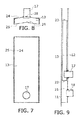
- Fig. 7 - 9 show an example of the implementation of the flow channel 13 and of its fitting in the water space 21 of the heat recovery chimney 10.
- the flow channel 13 consists of two elongated substantially U-shaped pieces, i.e. a cover part 24 that faces the jacket pipe 12 and a base part 25 that faces the flue pipe 11.
- folds 28, 29 are centrally formed both in the cover part 24 and the base part 25 of the flow channel 13 in the direction of the length so that the cover part 24 becomes convex and the base part 25 correspondingly concave.
- the depth dimension of the flow channel 13, i.e. its extent in the radial direction of the heat recovery chimney 10 is substantially smaller than the width dimension of the flow channel 13, i.e. its extent in the circumferential direction of the heat recovery chimney 10.
- the inlet coupling 17 is suitably connected to the cover part 24 of the flow channel 13 by welding.
- the flow channel 13 is assembled from the cover part 24 and the base part 25 so that said U-shaped cover part and base part are made with a fitting as tight as possible and are connected together by striking them against each other.
- the bottom end 22 of the flow channel 13 is closed and the top end 23 is open.
- the flow channel 13 is fitted inside the jacket pipe 12 by first welding the inlet coupling 17 to the cover part 24, connecting the cover part 24 and the base part 25 to each other, passing the flow channel 13 through the jacket pipe 12 so as to accommodate the inlet coupling 17 in an opening formed in the jacket pipe 12 and welding the inlet coupling 17 to the jacket pipe 12.
- the heat recovery chimney 10 according to the invention is applicable for use in connection with a block flue known in the prior art.
- the block flue is assembled by masoning from flue blocks 30 having a vertical through hole 31 for accommodating the flue pipe which consists e.g. of a steel pipe and/or a ceramic pipe and an insulation thereon.
- the heat recovery chimney 10 according to the invention is, by virtue of its structure, smooth on the external surface and suitable in size into the normal flue block 30, the invention provides a possibility to use the heat recovery chimney 10 in connection with a block flue.
- the heat recovery chimney 10 according to the invention functions as an insert of a block flue, i.e. a flue formed from flue blocks 30.
- flue blocks 30 are masoned in the normal way into a flue, in the hole 31 of which the heat recovery chimney 10 according to the invention is fitted with a thermal insulation layer 32 fitted thereon. It is also possible to assemble the flue so that the chimney 10 according to the invention is first installed in its place and the flue blocks 30 are passed thereon and masoned in their positions.
Landscapes
- Engineering & Computer Science (AREA)
- Mechanical Engineering (AREA)
- General Engineering & Computer Science (AREA)
- Chemical & Material Sciences (AREA)
- Combustion & Propulsion (AREA)
- Physics & Mathematics (AREA)
- Thermal Sciences (AREA)
- Chimneys And Flues (AREA)
- Incineration Of Waste (AREA)
Applications Claiming Priority (1)
| Application Number | Priority Date | Filing Date | Title |
|---|---|---|---|
| FI20135251A FI124829B (fi) | 2013-03-15 | 2013-03-15 | Lämmön talteenottopiippu |
Publications (2)
| Publication Number | Publication Date |
|---|---|
| EP2778535A2 true EP2778535A2 (fr) | 2014-09-17 |
| EP2778535A3 EP2778535A3 (fr) | 2014-11-19 |
Family
ID=50277065
Family Applications (1)
| Application Number | Title | Priority Date | Filing Date |
|---|---|---|---|
| EP14159831.8A Withdrawn EP2778535A3 (fr) | 2013-03-15 | 2014-03-14 | Dispositif de récupération de chaleur pour conduit de fumée |
Country Status (2)
| Country | Link |
|---|---|
| EP (1) | EP2778535A3 (fr) |
| FI (1) | FI124829B (fr) |
Cited By (1)
| Publication number | Priority date | Publication date | Assignee | Title |
|---|---|---|---|---|
| WO2023136995A1 (fr) * | 2022-01-14 | 2023-07-20 | Rheem Manufacturing Company | Dispositif de récupération d'énergie et procédé d'utilisation d'un dispositif de récupération d'énergie |
Family Cites Families (4)
| Publication number | Priority date | Publication date | Assignee | Title |
|---|---|---|---|---|
| FR584246A (fr) * | 1923-10-10 | 1925-02-02 | Appareils de récupération de chaleur | |
| US4231350A (en) * | 1978-07-20 | 1980-11-04 | Marsh Dean E | Hot water boiler |
| DE10062390A1 (de) * | 2000-12-14 | 2002-07-11 | Harald Horlbeck | Erschließung vorhandener Energieresourcen aus Abgaswärme von Verbrennungsanlagen |
| DE102008035407A1 (de) * | 2008-07-29 | 2010-02-04 | Martin Endres | Wärmetauscher |
-
2013
- 2013-03-15 FI FI20135251A patent/FI124829B/fi not_active IP Right Cessation
-
2014
- 2014-03-14 EP EP14159831.8A patent/EP2778535A3/fr not_active Withdrawn
Non-Patent Citations (1)
| Title |
|---|
| None |
Cited By (1)
| Publication number | Priority date | Publication date | Assignee | Title |
|---|---|---|---|---|
| WO2023136995A1 (fr) * | 2022-01-14 | 2023-07-20 | Rheem Manufacturing Company | Dispositif de récupération d'énergie et procédé d'utilisation d'un dispositif de récupération d'énergie |
Also Published As
| Publication number | Publication date |
|---|---|
| EP2778535A3 (fr) | 2014-11-19 |
| FI124829B (fi) | 2015-02-13 |
| FI20135251L (fi) | 2014-09-16 |
Similar Documents
| Publication | Publication Date | Title |
|---|---|---|
| US8056553B2 (en) | Condensate pan with condensate trap | |
| US5775318A (en) | Forced air condensing furnace and heat exchanger manifold therefor | |
| US4481935A (en) | Flue pipe connection | |
| JP4841567B2 (ja) | 潜熱熱交換器 | |
| CN204787951U (zh) | 返流式套管蒸发器 | |
| US9140450B2 (en) | Retrofitted corrosive resistant venting system | |
| US20080066694A1 (en) | Gas water heater | |
| JP6840008B2 (ja) | 熱交換器、熱交換ユニットおよび熱源機 | |
| EP2778535A2 (fr) | Dispositif de récupération de chaleur pour conduit de fumée | |
| US9631877B2 (en) | Furnace heat exchanger coupling | |
| EP1813884A2 (fr) | Unité de condensation | |
| JP2014070800A (ja) | 燃焼装置 | |
| CN203231544U (zh) | 热交换器装置和具有其的热水器 | |
| KR100687389B1 (ko) | 화로벽 구조 | |
| KR101339850B1 (ko) | 잠열 열교환기의 조립방법 및 그 잠열 열교환기 | |
| EP3097366B1 (fr) | Chaudière sectionnable | |
| CN216448666U (zh) | 一种快装式碳化硅换热器 | |
| KR101994232B1 (ko) | 보일러용 열교환장치 | |
| CN217636158U (zh) | 换热器 | |
| KR200449056Y1 (ko) | 콘덴싱 보일러용 열교환기 | |
| CN223939653U (zh) | 一种采暖炉冷凝水、倒灌水收集结构 | |
| ITMI20091981A1 (it) | Scambiatore di calore con dispositivo di scarico fumi perfezionato | |
| WO2018040601A1 (fr) | Ensemble carneau de chauffe-eau, et chauffe-eau | |
| CN220229568U (zh) | 冷凝换热器及燃气设备 | |
| CN214950682U (zh) | 整体式三层盘管烟气两回程热载体炉 |
Legal Events
| Date | Code | Title | Description |
|---|---|---|---|
| 17P | Request for examination filed |
Effective date: 20140314 |
|
| AK | Designated contracting states |
Kind code of ref document: A2 Designated state(s): AL AT BE BG CH CY CZ DE DK EE ES FI FR GB GR HR HU IE IS IT LI LT LU LV MC MK MT NL NO PL PT RO RS SE SI SK SM TR |
|
| AX | Request for extension of the european patent |
Extension state: BA ME |
|
| PUAI | Public reference made under article 153(3) epc to a published international application that has entered the european phase |
Free format text: ORIGINAL CODE: 0009012 |
|
| PUAL | Search report despatched |
Free format text: ORIGINAL CODE: 0009013 |
|
| AK | Designated contracting states |
Kind code of ref document: A3 Designated state(s): AL AT BE BG CH CY CZ DE DK EE ES FI FR GB GR HR HU IE IS IT LI LT LU LV MC MK MT NL NO PL PT RO RS SE SI SK SM TR |
|
| AX | Request for extension of the european patent |
Extension state: BA ME |
|
| RIC1 | Information provided on ipc code assigned before grant |
Ipc: F24B 1/183 20060101ALI20141010BHEP Ipc: F24B 9/00 20060101AFI20141010BHEP Ipc: F28D 21/00 20060101ALI20141010BHEP |
|
| STAA | Information on the status of an ep patent application or granted ep patent |
Free format text: STATUS: THE APPLICATION IS DEEMED TO BE WITHDRAWN |
|
| 18D | Application deemed to be withdrawn |
Effective date: 20150520 |