EP2778541B1 - Circuit destiné à faire baisser la température de retour primaire dans des installations de chauffage à distance - Google Patents
Circuit destiné à faire baisser la température de retour primaire dans des installations de chauffage à distance Download PDFInfo
- Publication number
- EP2778541B1 EP2778541B1 EP13159617.3A EP13159617A EP2778541B1 EP 2778541 B1 EP2778541 B1 EP 2778541B1 EP 13159617 A EP13159617 A EP 13159617A EP 2778541 B1 EP2778541 B1 EP 2778541B1
- Authority
- EP
- European Patent Office
- Prior art keywords
- transfer medium
- heat transfer
- heat
- pipe system
- heat exchanger
- Prior art date
- Legal status (The legal status is an assumption and is not a legal conclusion. Google has not performed a legal analysis and makes no representation as to the accuracy of the status listed.)
- Not-in-force
Links
- 238000010438 heat treatment Methods 0.000 title claims description 134
- 230000003247 decreasing effect Effects 0.000 title 1
- 238000012546 transfer Methods 0.000 claims description 486
- 239000000872 buffer Substances 0.000 claims description 125
- XLYOFNOQVPJJNP-UHFFFAOYSA-N water Substances O XLYOFNOQVPJJNP-UHFFFAOYSA-N 0.000 claims description 41
- 239000003651 drinking water Substances 0.000 claims description 17
- 235000020188 drinking water Nutrition 0.000 claims description 16
- 238000000034 method Methods 0.000 claims description 9
- 239000012530 fluid Substances 0.000 claims description 7
- 238000002156 mixing Methods 0.000 claims description 4
- 238000011144 upstream manufacturing Methods 0.000 claims 1
- 238000003860 storage Methods 0.000 description 88
- 208000007764 Legionnaires' Disease Diseases 0.000 description 27
- 241000589248 Legionella Species 0.000 description 25
- 238000001816 cooling Methods 0.000 description 8
- 230000008901 benefit Effects 0.000 description 6
- 244000052616 bacterial pathogen Species 0.000 description 4
- 238000009413 insulation Methods 0.000 description 4
- 238000013461 design Methods 0.000 description 3
- 230000000694 effects Effects 0.000 description 3
- 238000000605 extraction Methods 0.000 description 3
- 230000002349 favourable effect Effects 0.000 description 3
- 238000003809 water extraction Methods 0.000 description 3
- 230000004913 activation Effects 0.000 description 2
- 230000002308 calcification Effects 0.000 description 2
- 238000004140 cleaning Methods 0.000 description 2
- 230000035622 drinking Effects 0.000 description 2
- 238000011049 filling Methods 0.000 description 2
- 238000005338 heat storage Methods 0.000 description 2
- 238000012423 maintenance Methods 0.000 description 2
- 239000000203 mixture Substances 0.000 description 2
- 230000009467 reduction Effects 0.000 description 2
- 241001465754 Metazoa Species 0.000 description 1
- 238000010521 absorption reaction Methods 0.000 description 1
- 230000009471 action Effects 0.000 description 1
- 235000012206 bottled water Nutrition 0.000 description 1
- 230000003139 buffering effect Effects 0.000 description 1
- 238000005266 casting Methods 0.000 description 1
- 238000002485 combustion reaction Methods 0.000 description 1
- 238000004891 communication Methods 0.000 description 1
- 239000004020 conductor Substances 0.000 description 1
- 238000010276 construction Methods 0.000 description 1
- 238000011109 contamination Methods 0.000 description 1
- 230000001419 dependent effect Effects 0.000 description 1
- 238000011161 development Methods 0.000 description 1
- 230000018109 developmental process Effects 0.000 description 1
- 238000010586 diagram Methods 0.000 description 1
- 230000007613 environmental effect Effects 0.000 description 1
- 238000011010 flushing procedure Methods 0.000 description 1
- 239000006260 foam Substances 0.000 description 1
- 239000013505 freshwater Substances 0.000 description 1
- 230000006870 function Effects 0.000 description 1
- 239000000383 hazardous chemical Substances 0.000 description 1
- 230000036541 health Effects 0.000 description 1
- 231100000206 health hazard Toxicity 0.000 description 1
- 239000013529 heat transfer fluid Substances 0.000 description 1
- 239000008236 heating water Substances 0.000 description 1
- 238000007654 immersion Methods 0.000 description 1
- 238000003973 irrigation Methods 0.000 description 1
- 230000002262 irrigation Effects 0.000 description 1
- 230000000670 limiting effect Effects 0.000 description 1
- 239000007788 liquid Substances 0.000 description 1
- 238000004519 manufacturing process Methods 0.000 description 1
- 238000013021 overheating Methods 0.000 description 1
- 244000052769 pathogen Species 0.000 description 1
- 238000003825 pressing Methods 0.000 description 1
- 230000001105 regulatory effect Effects 0.000 description 1
- 238000003303 reheating Methods 0.000 description 1
- 230000003252 repetitive effect Effects 0.000 description 1
- 230000004044 response Effects 0.000 description 1
- 238000004904 shortening Methods 0.000 description 1
- 229910001220 stainless steel Inorganic materials 0.000 description 1
- 239000010935 stainless steel Substances 0.000 description 1
- 230000001954 sterilising effect Effects 0.000 description 1
- 230000009182 swimming Effects 0.000 description 1
- 230000007704 transition Effects 0.000 description 1
- 238000005406 washing Methods 0.000 description 1
- 239000002918 waste heat Substances 0.000 description 1
Images


Classifications
-
- F—MECHANICAL ENGINEERING; LIGHTING; HEATING; WEAPONS; BLASTING
- F24—HEATING; RANGES; VENTILATING
- F24D—DOMESTIC- OR SPACE-HEATING SYSTEMS, e.g. CENTRAL HEATING SYSTEMS; DOMESTIC HOT-WATER SUPPLY SYSTEMS; ELEMENTS OR COMPONENTS THEREFOR
- F24D10/00—District heating systems
- F24D10/003—Domestic delivery stations having a heat exchanger
-
- F—MECHANICAL ENGINEERING; LIGHTING; HEATING; WEAPONS; BLASTING
- F24—HEATING; RANGES; VENTILATING
- F24D—DOMESTIC- OR SPACE-HEATING SYSTEMS, e.g. CENTRAL HEATING SYSTEMS; DOMESTIC HOT-WATER SUPPLY SYSTEMS; ELEMENTS OR COMPONENTS THEREFOR
- F24D17/00—Domestic hot-water supply systems
- F24D17/0015—Domestic hot-water supply systems using solar energy
- F24D17/0021—Domestic hot-water supply systems using solar energy with accumulation of the heated water
-
- Y—GENERAL TAGGING OF NEW TECHNOLOGICAL DEVELOPMENTS; GENERAL TAGGING OF CROSS-SECTIONAL TECHNOLOGIES SPANNING OVER SEVERAL SECTIONS OF THE IPC; TECHNICAL SUBJECTS COVERED BY FORMER USPC CROSS-REFERENCE ART COLLECTIONS [XRACs] AND DIGESTS
- Y02—TECHNOLOGIES OR APPLICATIONS FOR MITIGATION OR ADAPTATION AGAINST CLIMATE CHANGE
- Y02B—CLIMATE CHANGE MITIGATION TECHNOLOGIES RELATED TO BUILDINGS, e.g. HOUSING, HOUSE APPLIANCES OR RELATED END-USER APPLICATIONS
- Y02B30/00—Energy efficient heating, ventilation or air conditioning [HVAC]
- Y02B30/17—District heating
-
- Y—GENERAL TAGGING OF NEW TECHNOLOGICAL DEVELOPMENTS; GENERAL TAGGING OF CROSS-SECTIONAL TECHNOLOGIES SPANNING OVER SEVERAL SECTIONS OF THE IPC; TECHNICAL SUBJECTS COVERED BY FORMER USPC CROSS-REFERENCE ART COLLECTIONS [XRACs] AND DIGESTS
- Y02—TECHNOLOGIES OR APPLICATIONS FOR MITIGATION OR ADAPTATION AGAINST CLIMATE CHANGE
- Y02E—REDUCTION OF GREENHOUSE GAS [GHG] EMISSIONS, RELATED TO ENERGY GENERATION, TRANSMISSION OR DISTRIBUTION
- Y02E20/00—Combustion technologies with mitigation potential
- Y02E20/14—Combined heat and power generation [CHP]
Definitions
- the invention relates to a pipeline system according to the preamble of claim 1 and to a method for heating heat transfer medium in a heat pipe system of a pipeline system according to claim 11.
- piping systems which have a first heat pipe system which draws heat from the district heating network supply and returns a heat transfer medium cooled by heat extraction into the district heating network return of the district heating network.
- part of such a piping system is a second heat pipe system, which removes heat from the first heat pipe system via a heat exchanger in order to heat a second heat transfer medium.
- the first heat transfer medium cools in the first heat pipe system.
- Such a piping system is for example from the EP 1 455 140 A1 known.
- this document teaches a multi-stage water heating.
- a second heat transfer medium in this case drinking water, is raised in response to the temperature of the primary return to a corresponding temperature level.
- the temperature of the second heat transfer medium can be thermally raised after passing through the preheater by serving as an intermediate heat exchanger heat exchanger.
- the intermediate heater can also be designed as a solar system.
- a reheater raises the temperature of the second heat transfer medium to target temperature for a hot water supply.
- a first heat exchanger is used for heating a heating circuit
- a second and a third heat exchanger are used in cascade for DHW heating. They transfer heat from a heat pipe system to a drinking water pipe system.
- the first heat exchanger is used for circulating reheating, the other for preheating fresh water, which is supplied to the circulation circuit to compensate for withdrawal losses.
- the two heat exchangers form a two-stage cascade. As long as no removal takes place from the circulation circuit, its temperature is kept at the predetermined level solely by using the second heat exchanger.
- the primary-side return flow of the second heat exchanger is supplied to the third heat exchanger via the primary-side inlet connection and flows through it on the primary side. The cooled return flow is fed back into the district heating network after leaving the primary-side return connection.
- the EP 1 403 593 A2 teaches a heat transfer medium buffer storage, which is designed as a heat transfer medium tank.
- First heating means are arranged in a lower portion of the heat transfer medium buffer storage and second heating means are arranged in an upper portion of the heat transfer medium storage tank.
- the heating means can be heated, for example, by a solar panel.
- EP 1 764 564 A1 is a drinking water heating system with a piping system according to the preamble of claim 1 known. In it, two zones of heat transfer to the drinking water system are created by heating water in a heat transfer medium storage tank into two zones.
- the DE 20 2006 018 246 U1 deals with a component to protect small hot water temperature fluctuations in hot water systems with flow system.
- the component should achieve a circulation temperature of 70 ° C under all load conditions.
- the invention has for its object to improve a piping system of the type described above in which heat is transferred from a first heat pipe system to a second heat pipe system.
- the efficiency of the heat removal should be increased, a higher temperature spread of the heat transfer medium between heat flow and heat return in the first heat pipe system can be achieved, a reduction of the calcification and improved heat transfer medium heating for a second heat pipe system allows.
- an improved method for heating a second heat transfer medium in the second heat pipe system should be provided in order to maintain a temperature of the second heat transfer medium before being fed back into the district heating network return of less than 45 ° C in particular to comply with the requirements of the heat suppliers.
- the object underlying the invention is achieved by a piping system according to claim 1. Further, it is achieved by a method according to claim 11.
- a heat pipe system in the sense of the invention is a pipe system which is used to be able to conduct a heat transfer medium, so that heat can be exchanged and removed between the heat pipe systems depending on the temperature of another heat pipe system connected thereto in heat transfer connection.
- a district heating network in the sense of the invention is a pipe network provided by a public or private district heating supplier or the public sector, which connects thermal power stations with the heat pipe systems of consumers.
- a district heating network usually has a district heating network feed with heated heat transfer medium and a district heating network return with the opposite cooled heat transfer medium.
- the district heating supply flow usually begins at a cogeneration plant or heating plant, while the district heating network return also ends there. In this way, a cycle is provided in which a heating medium from a heat transfer medium is heated, the medium is provided via the district heating network flow to heat pipe systems of consumers and then the cooled heat transfer medium is fed into the district heating network return through which it returns to the power plant or heating plant passes.
- a heat transfer medium is the medium which is preferably transported in the district heating network with a pump.
- a heat transfer medium is often hot water or steam, for example at temperatures of 90 ° C to 180 ° C.
- steam as the heat transfer medium, the condensate of the cooled water vapor is fed back into the district heating network return.
- the advantage is achieved that a certain proportion of residual heat at high temperature, which is otherwise fed back into the district heating network return of the district heating network, can be used for preheating of the second heat transfer medium.
- the inventors have found a solution with which, contrary to prevailing prejudices, a heat transfer medium preheating of large quantities of a heat transfer medium can take place.
- a heat transfer medium buffer storage is provided in order to form a reservoir for the second heat transfer medium, so that more volume is available for temporarily storing the second heat transfer medium and thus also for buffering heat compared to a simple pipeline. Thus even more heat provided by the district heating network feed can actually be used by the consumer via the primary return.
- heat energy can be stored in low-consumption times, which can be delivered in periods of high consumption.
- the spread of the district heating network supply and the district heating network return heat can be further increased as a result of heat storage. This, in turn, may result in an additional cooling of the heat carrier medium, for example in cooling towers, only to a lesser extent before renewed heating of the heat transfer medium in a cogeneration plant.
- the delivery of expensive heat output into the environment can thus be reduced and CO 2 can be saved.
- the number of cooling towers can be reduced in the design and construction of a district heating network. The invention can therefore be both positive for environmental protection and on the other hand at the same time bring the consumer and the district heating provider enormous cost advantages and performance gains in the power plant.
- the heat transfer medium storage tank is compared with its heat transfer medium inlet, so an opening through which the second heat transfer medium enters the heat transfer medium buffer, sections widened.
- the heat transfer medium buffer storage can store a very large volume of the second heat transfer medium.
- the heat transfer medium buffer memory may therefore be an additional heat extraction from the primary flow almost unnecessary or at least reduced if the second heat transfer medium in the heat transfer medium buffer storage, ie the reservoir, already has a sufficiently high temperature.
- the second heat pipe system is set up so that only the second heat transfer medium is removed from the heat transfer medium buffer storage, even if the second heat transfer medium itself is taken from the second heat transfer medium. As long as no removal takes place from the second heat pipe system, so the second heat transfer medium rests in the reservoir. As a result, a particularly good heat absorption and heat storage can be possible.
- the heat transfer medium buffer storage is designed substantially circular cylindrical.
- the heat transfer medium inlet of the heat transfer medium buffer storage is in comparison to an inner diameter of the heat transfer medium buffer storage each perpendicular to the flow direction of the second heat transfer medium much smaller.
- the inner diameter of the heat transfer medium storage tank is at least 1.5 times, particularly preferably at least twice as large, at least three times as large, at least eight times as large, at least fifteen times as large, at least twenty times so perpendicular to the flow direction of the second heat transfer medium large or at least fifty times as large as the diameter of its heat transfer medium inlet.
- a particularly large reservoir for the second heat transfer medium can be provided in comparison with a normal pipe section, which does not have at least sections widening.
- the inner diameter of the diameter of a circular cylindrical heat transfer medium buffer memory is designed as a pipe connection.
- a preferred heat transfer medium buffer storage is a heat transfer medium tank.
- the heat transfer medium is water, in particular drinking water
- the heat transfer medium storage tank is particularly preferably a water tank.
- Such tanks as reservoirs are preferably easy to obtain, inexpensive, low-maintenance and available in large selection on the market.
- they preferably provide a large storage volume, more preferably a volume for temporarily storing the second heat transfer medium of more than 100 liters, more than 200 liters, more than 400 liters, more than 750 liters or more than or much more than 1000 liters.
- a storage volume of 300 liters is preferred.
- a particularly preferred capacity for the heat transfer medium tank is twice the daily requirement for the second heat transfer medium.
- the heat transfer medium tank can be made of stainless steel. It can also or alternatively thermo-glazed, galvanized or plastic coated. Preferably, it has a cylindrical, more preferably a circular cylindrical shape. Most preferably, the heat transfer medium inlet and a heat transfer medium outlet of the heat transfer medium buffer storage are exactly opposite. Thus, a particularly favorable flow profile and a particularly favorable heat output for the second heat transfer medium can be achieved.
- a preferred heat transfer medium storage tank also has a thermal insulation, preferably on its outside. It is particularly preferred that a heat insulation is foamed onto the outside as rigid foam. Such a thermal insulation can very effectively reduce unwanted heat release from the second heat transfer medium in the heat transfer medium storage tank through the wall of the heat transfer medium storage tank, so that advantageously no significant amount of heat is lost as radiated heat.
- the pipe section which fluidly connects the first heat exchanger to the second end of the first heat pipe system, passes through the heat transfer medium storage tank to heat the second heat transfer medium.
- Said pipe section also called primary return, is thus performed so that the heat transfer medium buffer storage with residual heat directly, for example via a heating coil, can be heated. It may alternatively or additionally be helically wound around the heat transfer medium buffer storage.
- the primary return ie the pipe section between the first heat exchanger and the second end of the first heat pipe system, extends in sections into the heat transfer medium buffer memory.
- the primary return is arranged only on or in a certain portion of the heat transfer medium buffer memory. It is particularly preferred that it is arranged only on or in 10%, 20%, 30% 40% or even more preferably 50% of the heat transfer medium buffer storage. Alternatively, however, it can also be arranged outside or inside along up to 100% of the heat transfer medium buffer storage, based on the length of the heat transfer medium buffer storage. Thus, a particularly large portion of the primary return heat transferred to the second heat transfer medium in the heat transfer medium buffer memory. Finally, the primary return preferably exits from the heat transfer medium storage tank then ends second end of the first heat pipe system again.
- the first heat transfer medium between the first heat exchanger and heat transfer medium buffer memory still has a primary residual heat of preferably about 50 ° C to 60 ° C and in the pipe segment of the first heat pipe system, which heats the pipe segment, which heats the heat transfer medium buffer , is downstream, in the flow direction, still a remaining Residual heat of preferably 35 ° C or less.
- the second heat transfer medium in the heat transfer medium buffer storage of about 10 ° C, which may correspond substantially to the temperature in a heat transfer medium network of the second heat transfer medium, from which the second heat transfer medium is removed, and which corresponds substantially to the typical temperature of drinking cold water to warm to about 20 ° C to 40 ° C.
- the second heat transfer medium must then be heated by the first heat exchanger only by about 20 to 40 K in order to achieve a target temperature of about 60 ° C, for example, at a withdrawal point in drinking water heaters. It must therefore be removed from the primary flow through the first heat exchanger much less heat. An energy-efficient heat extraction is thus achievable.
- the second heat exchanger is designed on the secondary side as a heat transfer medium buffer memory.
- a heat transfer medium can be provided with a reservoir for the second heat transfer medium in a single structural unit, which can have an advantageous effect on the production costs.
- the heat exchanger can also be connected via a heat connection to a separate heat transfer medium buffer storage. This can increase the flexibility and / or the operational reliability with respect to the arrangement, for example by the heat from the second heat exchanger via thermally conductive materials is forwarded to a separate reservoir.
- the second heat exchanger is on the secondary side as a heat transfer medium tank, preferably with already described special heat insulation, designed to allow a particularly compact design.
- the second heat pipe system comprises a circulation circuit. It is desirable that, for example, hot water as the second heat transfer medium is already available in a short time after opening a water extraction device, for example a faucet. This can advantageously be achieved by a circulation circuit.
- the second heat transfer medium is passed in constant flow through the first heat exchanger, so that the entire present in the circulation heat transfer medium has a substantially constant high temperature. It is preferably 55 ° C, can but also at 60 ° C or at 50 ° C. Accordingly, the temperature is usually preferably in an interval between 50 ° C and 60 ° C. Also deviating temperatures are possible.
- the circulation circuit is refilled with a second heat transfer medium from the heat transfer medium buffer storage as soon as a heat transfer medium removal takes place from the circulation circuit. Then also second heat transfer medium flows automatically from the network into the heat transfer medium buffer storage.
- the second heat pipe system can also be designed without a circulation circuit. This can be a cost effective solution if a longer lead time is acceptable before warm water carrier medium is to be available after opening the water extractor.
- the heat transfer medium is preferably obtained via a simple pipe segment from the heat transfer medium buffer storage, the pipe segment passed on the first heat exchanger, while the heat transfer medium heated and then removed from the water extraction device, and always at the moment when the water extraction device is opened to remove water.
- the second heat transfer medium when it passes the first heat exchanger, opposite to the flow direction of the first heat transfer medium flows. So a very favorable heat transfer can be guaranteed.
- the flow directions can also be rectified, for example when the grid connection situation requires it.
- a legionella changeover valve is preferably arranged in the circulation circuit.
- a heating of the heat transfer medium to up to 60 ° C or more done to effectively kill Legionella and other germs can.
- it is connected in series with the circulation pump. It preferably allows the circulation time of the second heat transfer medium to be reduced by shortening the distance, so that a higher temperature of the second heat transfer medium can be achieved.
- a fluid connection is provided, via which the second heat transfer medium can be fed again into the heat transfer medium buffer storage, after it has already been heated by the first heat exchanger and the second heat exchanger.
- the second heat pipe system comprises a circulation circuit that communicates with the heat transfer medium buffer tank is fluid-connected to initiate the second heat transfer medium from the circulation circuit in the heat transfer medium buffer memory can.
- the idea is therefore to be able to achieve, in particular temporarily, additional heating of the second heat transfer medium within the heat transfer medium buffer storage.
- the fluid connection is preferably made via a valve.
- the second heat transfer medium from the circulation circuit in the or the heat transfer medium buffer storage are introduced, flow through the heat transfer medium buffer storage and then flow back into the circulation circuit.
- the valve preferably serves as a legionella switching valve, more preferably as a second legionella switching valve provided in addition to the first legionella switching valve.
- a circulation pump can preferably serve as a charge pump for the heat transfer medium storage tank with appropriate valve position. Alternatively, a separate charge pump may be present.
- a Legionella killing for the or the heat transfer medium buffer memory can be provided. This allows the user to be better protected from Legionella or other pathogens.
- the previously described feeding of the second heat transfer medium already heated by the first and the second heat exchanger takes place via the heat transfer medium inlet of the heat transfer medium buffer storage, preferably via the previously described valve.
- the second legionella switching valve connects the circulation circuit with the heat transfer medium inlet of the heat transfer medium buffer memory.
- a second heat transfer medium for example, 60 ° C hot water, passed from the circulation circuit in the buffer memory, preferably pumped to be able to kill there any existing Legionella or other germs can. The water then flows back into the circulation circuit.
- the heat transfer medium buffer memory is in a flushing position of the valve so part of the circulation circuit, if a circulation circuit is present.
- the simple pipe section can be heated, for example, by an electric trace heating, so as to allow heating of the second heat transfer medium in this pipe section.
- a preferred Elektrobegleitsammlungung is helically wound around the pipe section, more preferably on a length which is greater than half the length of the pipe section.
- the second heat transfer medium from the circulation circuit via the heat transfer medium outlet of the heat transfer medium buffer storage can be supplied to the heat transfer medium buffer memory to achieve the sterilizing effect.
- a second Legionellenumschaltventil be designed in the circulation circuit for this purpose so that the heat transfer medium buffer memory can be temporarily included in the circulation so that it is filled against the usual flow direction, ie from the heat transfer medium outlet to the heat transfer medium inlet.
- a flow connection between the circulation circuit and heat transfer medium inlet of the heat transfer medium buffer storage, ie at a point between the heat transfer medium buffer storage and heat transfer medium transfer point of the second heat transfer medium is set, which can be preferably temporarily closed by an additional legionella protection flow valve.
- the second heat transfer medium can be fed back from the circulation circuit in the heat transfer medium storage tank contrary to the usual flow direction and dammed therein.
- a particularly inexpensive and functional and therefore particularly preferred solution can be provided if the connection between the heat transfer medium inlet of the heat transfer medium buffer storage and the circulation circulation is realized as a T branch in the circulation circuit.
- the T-branch is provided with one, preferably the second, Legionellenumschaltventil.
- a Legionellenumschaltventil on the fluid connection between the heat transfer medium drain and circulation circuit and on the legionella protection flow valve can then be dispensed with.
- a Legionellentik for the heat transfer medium buffer memory can be realized with only a single valve, which allows a return of the second heat transfer medium via the heat transfer medium flow.
- a heat transfer medium is arranged on the heat transfer medium buffer memory in order to transfer heat to the second heat transfer medium from a heat source which provides heat in addition to the heat transfer from the first heat transfer medium.
- the heat source is a solar thermal system.
- the heat source may also be, for example, a geothermal plant, a waste heat plant, a combustion furnace or an electric heat source. In this way it can be achieved that the second heat transfer medium still requires less heat through the first heat exchanger from the primary flow to be heated to the target temperature.
- a solar thermal system may, for example, flat solar panels or vacuum tube collectors or parabolic trough collectors or solar towers.
- the second heat transfer medium can therefore be heated sufficiently and inexpensively solely by the additional heat source.
- the first heat transfer medium in the first heat pipe system can be heated by an additional heat source, thus indirectly also the second heat transfer medium stronger to heat up. If such an additional heat source is present, then it is preferred that the heat transfer medium buffer storage has a capacity of preferably 1000 liters for the second heat transfer medium.
- the additional heat can be used particularly advantageous. For example, overheating of the second heat transfer medium may also be omitted.
- a water heating by means of the residual heat from the first heat pipe system while in a second portion of the heat transfer medium buffer memory , which is further on the flow path of the second heat transfer medium of the heat transfer medium transfer station for the second heat transfer medium compared to the first section, a heating by the additional heat source, such as solar thermal, takes place.
- the first portion is located at a lower height level than the second portion.
- a heating from an initial temperature of about 10 ° C to a transition temperature of about 40 ° C take place and in the second section, a further heating to between 40 ° C and 60 ° C.
- the second heat transfer medium flows through only the portion of the heat transfer medium buffer storage, in which the heating takes place by means of residual heat from the first heat pipe system and then flows through the portion of the heat transfer medium buffer memory, in which the heating takes place by means of solar thermal. It is obvious that an already so strongly preheated second heat transfer medium hardly requires any further heat supply via the first heat exchanger.
- the district heating network supply transfer station and / or the district heating network return transfer station and / or a heat transfer medium transfer station for the second heat transfer medium form a unit with the piping system.
- a particularly compact design of the pipeline system can be achieved. It can be a complete system, for example in the form of a compact station, can be provided, which can be installed with little space, for example, in a basement of a house.
- a District heating network delivery station preferably comprises elements such as valves, regulators, heat meters or flow meters.
- the connection to the district heating network can be easily produced and monitored in a time-saving manner.
- a district heating network return transfer station preferably also includes elements such as valves, regulators, heat meters or flow meters. So here too, the connection to the district heating network can be easily produced and monitored. In particular, comparison values for measured values which are determined in the district heating network feed-forward transfer station can be determined, if appropriate, in the district heating network return transfer station.
- a plurality of heat transfer medium storage tanks may have the advantage that, if necessary, a larger amount of the second heat transfer medium is available than can be stored in a simple piping system, a single heat transfer medium buffer or even a single circulation circuit.
- the demand for heat transfer medium storage tanks depends, for example, on the expected second heat transfer medium requirement, for example the water requirement. With the expected water consumption of about 600 liters per day, a buffer volume of about 300 liters capacity may be adequate.
- heat transfer medium storage tanks there may be two heat transfer medium storage tanks, each with a capacity of 150 liters, or, if required, for example, three heat transfer medium storage tanks, each with a capacity of 300 liters.
- some or all of the plurality of heat transfer medium storage buffers are arranged in the form of a parallel circuit.
- the same heating ambient condition can be present in these heat transfer medium storage tanks, which makes it possible to provide a large amount of second heat transfer medium at the same temperature.
- the first heat transfer medium is water and the second heat transfer medium is drinking water.
- the second heat pipe network is preferably a drinking water pipe network.
- Drinking water in the context of the invention is such water, which has a water quality that makes the water appear suitable for drinking, for example. Accordingly, it is such water, generally taken from a drinking water pipe, so a drinking water pipe system, a house can be. It thus corresponds to the water that can be taken in a household a faucet and has a hygiene quality that makes it safe for humans to eat as food.
- the second heat pipe network can also contain such water that is not drinkable.
- the heat pipe network is preferably a heating pipe network that provides heat for heating, for example, rooms, or an irrigation network that provides hot water for casting plants, for example, or a washing water network that provides warm water for cleaning runways, roads, vehicles, paths or facades, for example , It may also be, for example, a fire water network when preheated extinguishing water is to be provided.
- the piping system is a house piping system.
- a house can be a house, a stable, a hotel, a barracks building, a block of flats, a commercial building, a warehouse, a swimming pool, a sports hall, a greenhouse or even an administration building, in general thus simply a commercial building.
- any building in which humans or animals can reside can be a house within the meaning of the invention.
- an outdoor piping system in question that is laid in the open air in the ground. This is preferably the case when a second heat transfer medium is to be provided in a substantially open area and not in a building.
- the first heat exchanger is a shell-and-tube heat exchanger.
- a shell and tube heat exchanger has proven to be a particularly advantageous heat exchanger, since it has a large surface area and thus a good heat transfer between the first heat pipe system and the second heat pipe system is made possible.
- other heat exchangers can be used, such as plate radiators, U-tube heat exchangers or spiral heat exchangers. Other types known in the art may also be suitable.
- the second heat exchanger can also be designed in this way.
- a jet pump is arranged in the heat pipe system. It is desirable to introduce the first heat transfer medium at a temperature of 60 ° C to 70 ° C in the heat exchanger.
- the first heat transfer medium is often with a disproportionately high temperature of 90 ° C, for example, in the summer, to 180 ° C, for example in winter, provided from the district heating network supply.
- a jet pump may be advantageous to lower the temperature of the heat transfer medium before entering the heat exchanger in order to counteract, for example, a calcification. For this purpose, it can mix the cooled heat transfer medium from the primary return flow between the first heat exchanger and the second end of the heat pipe system to the first heat transfer medium which is introduced at high temperature from the district heating network through the first end into the first heat pipe system.
- the jet pump has two inputs and one output.
- the first inlet is fluidly connected to the first end of the heat pipe system.
- the second input is fluidly connected via a branch pipe, so an admixing, with the pipe section between the first heat exchanger and the second end of the heat pipe system, or between the second heat exchanger and the second end of the first heat pipe system.
- the second input may be connected to a heat transfer medium discharge opening of the first heat exchanger, for example by means of a T connection.
- the outlet of the jet pump preferably leads in each case directly to a heat carrier inflow opening of the first heat exchanger.
- the first heat transfer medium which is between 90 ° C.
- a heat transfer medium having a temperature of about 60 ° C to 70 ° C is initiated.
- jet pumps of the manufacturers Bälz and ERST have proved to be particularly suitable. Instead of a jet pump, however, if this is desired for cost reasons, for example, but also a simple automatic mixing valve can be used. This can be a cheaper solution.
- the second heat transfer medium in the heat transfer medium buffer storage is additionally heated by a solar thermal system.
- a solar thermal system for example, water in a potable water storage tank where it is cached at rest may be more easily heated than in a piping system which is flowed through by the water at high speed.
- additional heating such as solar thermal heating
- free or inexpensive available heat can be used to preheat a large amount of the second heat transfer medium, so that only very little primary heat from the district heating network and must be transferred to the second heat transfer medium. This can have an advantageous effect on the consumption costs and connection costs.
- the second heat transfer medium first flows into a heat transfer medium buffer memory, which is formed by the secondary side of a second heat exchanger, there flows through a first portion of the second heat exchanger, wherein in the first section heat transfer means for transferring are arranged by residual heat from a first heat pipe system, then flows through a second portion of the heat transfer medium buffer memory, wherein in the second section heat transfer means for transferring heat from an additional heat source are arranged and finally flows from the heat transfer medium buffer memory in a circulation circuit by a first heat exchanger can remove additional heat from the first heat pipe system, which has a higher temperature than this residual heat, in the first section of the second heat is provided.
- the second heat transfer medium in the heat transfer medium buffer storage is preheated by residual heat from the first heat pipe system, then there is a further heating by solar thermal energy and finally takes place after flowing out of the Heat transfer medium buffer storage further heating by primary heat through the first heat exchanger only in so far as it is necessary to achieve the desired target temperature.
- a preferred target temperature of the second heat transfer medium is 55 ° C, but higher or lower target temperatures, such as 45 ° C or 65 ° C, or any temperature values therebetween or even outside this interval may be desired.
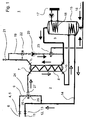
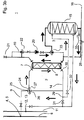
- FIG. 1 shows a first embodiment of a piping system 1 according to the invention, designed as a house piping system for drinking water heating, at the first, the basic features of such a piping system 1 are illustrated.
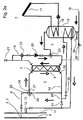
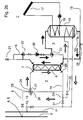
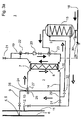
- the embodiments in the Figures 2 . 3 and 4 show comparable piping systems 1 according to the invention, each in details from the piping system 1 from FIG. 1 differ. The corresponding details will be discussed in due course. It goes without saying that the same reference numerals in the different exemplary embodiments stand for identical or comparable elements, so that repetitive statements relating to the respective exemplary embodiments are possible.
- a pipe system 1 comprises a first heat pipe system 2 and a second heat pipe system 3. Via a first end 4 of the first heat pipe system 2, a first heat transfer medium from a district heating network feed 6 is fed into the first heat pipe system 2 by means of a district heating network feed transfer station 5.
- the first heat transfer medium in this case is liquid water or water vapor at a temperature of for example 90 ° C in summer and 180 ° C in winter, for example.
- the arrows whose arrowheads are not filled and which are shown adjacent to the first heat pipe system 2 in the figures, each indicate the flow direction of the first heat transfer medium in the first heat pipe system. 2
- the first heat transfer medium flows in all three embodiments shown through a first pipe section and flows through a heat transfer medium inlet 7 on the primary side in a first heat exchanger 8 a.
- the first pipe section between the first end 4 of the heat pipe system 2 and the heat transfer medium inlet 7 is also referred to as the primary flow 9.
- the heat transfer medium flows through the first heat exchanger 8, in this case a shell-and-tube heat exchanger, by which heat stored in the first heat transfer medium can be transferred to a second heat transfer medium in the second heat pipe system 3.
- the second heat transfer medium contained in the second heat pipe system 3 is heated by the first heat exchanger 8.
- the second heat transfer medium is drinking water in the present example.
- the first heat transfer medium in the first heat pipe system 2 is cooled as it flows through the first heat exchanger 8, because part of its heat is released to the second heat transfer medium in the second heat pipe system 3.
- the first heat transfer medium leaves the first heat exchanger 8 through a heat transfer medium discharge opening 10 and then flows with a residual heat of about 50 ° C to 60 ° C in the direction of a district heating return 11, via a second end 12 of the first heat pipe system 2 and one on the second end arranged as a completion of the first heat pipe system 2 remote heating network return transfer station 13 is connected.
- the problem may in principle be that the first heat transfer medium in the pipe section between the heat transfer medium discharge opening 10 of the first heat exchanger 8 and the second end 12 of the first heat pipe system 2, which is also referred to as primary return 14, despite the heat transfer in the first heat exchanger 8 from the first heat pipe system 2 to the second Heat pipe system 3 still has a temperature which is well above a desired Fernellenetz Weglauftemperatur of about 35 C, for example, even at 50 ° C to 60 ° C.
- the second heat pipe system 3 has a heat transfer medium buffer storage as a reservoir for the second heat transfer medium.
- a much larger storage volume for heat is provided than in a simple conduit. Therefore, on the one hand, a large amount of the second heat transfer medium can be heated particularly well.
- the first heat transfer medium can be cooled more be to further reduce the return flow temperature of the first heat transfer medium in the district heating return 11.
- the residual heat removal takes place for preheating the second heat transfer medium as the last consumer heat removal from the first heat pipe system 2, before the first heat transfer medium reaches the second end 12 of the first heat pipe system 2.
- a second heat exchanger 15 is present in the heat pipe system 3. He provides the secondary side of the heat transfer medium buffer storage, as a cylindrical water tank. As can be seen, the water tank is widened in sections compared to its heat transfer medium inlet. The diameter of the water tank perpendicular to the flow direction is a multiple compared to the diameter of the heat transfer medium inlet.
- the heat transfer medium buffer storage is arranged in this case within the heat pipe system 3 immediately behind a heat transfer medium transfer point 16 of a heat transfer medium transfer station (not shown). This means a high temperature spread between the first heat transfer medium, which still has a temperature of between 50 ° C and 60 ° C in the primary return 14 behind the heat exchanger 8, and the second heat transfer medium, the network side usually provided with a temperature of about 10 ° C. becomes.
- the second heat transfer medium can be correspondingly preheated in the heat transfer medium buffer storage, which is the secondary side of the second heat exchanger 15, to a temperature of 20 ° C to 40 ° C.
- a solar thermal system 17 is present.
- the first heat pipe system 2, the second heat pipe system 3 and a pipe system of the solar thermal system 17 are fluid-separated.
- the solar thermal system 17 is connected to the second heat pipe system 3 thermally conductive.
- the solar thermal system 17 thus transfers heat directly to the second heat transfer medium within the heat transfer medium buffer of the second heat exchanger 15.
- the second heat transfer medium in the heat transfer medium buffer memory under common action of the residual heat preheating from the primary return 14 and the solar thermal even to temperatures of about 60 ° C are heated.
- the solar thermal system 17 is thermally coupled in a comparable manner to the second heat exchanger 15, as the pipe section of the first heat pipe system 2, which passes through the heat transfer medium buffer memory.
- a pipe segment 18 of the solar thermal system 17 passes through sections of the heat transfer medium storage tank and heats the second heat transfer medium there.
- this tube segment 18 of the solar thermal system 17 is arranged in a section of the heat transfer medium buffer storage, that is to say in this case in a section of the second heat exchanger 15, which, relative to the flow direction of the heat transfer medium, the first section in which the second Heat transfer medium is preheated via residual heat from the first heat pipe system 2, downstream.
- FIGS. 1 In the FIGS. 1 .
- exemplary embodiments are shown in which solar thermal energy and residual heat of the primary return 14 are transferred to the second heat transfer medium in each case in approximately one third of the heat transfer medium buffer storage tank through corresponding pipe segments.
- FIG. 3 If no solar thermal system 17 is provided. Instead, it's a pipe segment of the primary return 14 to almost the full length of the heat transfer medium buffer memory arranged in this. Thus, a particularly efficient heat removal from the primary return 14 and thus a greater cooling of the first heat transfer medium can be made possible.
- the second heat transfer medium flows preheated in a circulation circuit 19, and indeed whenever the second heat transfer medium is removed from the circulation circuit 19.
- the second heat transfer medium then passes through the first heat exchanger 8 to receive additional heat from the primary flow 9 of the first heat pipe system 2, ie primary heat, as needed.
- the first heat transfer medium and the second heat transfer medium in the region of the first heat exchanger 8 in the present embodiment flow in opposite directions to each other, whereby a good heat transfer can be ensured.
- a target temperature of the second heat transfer medium of about 55 ° C is desired.
- the additional primary heat transfer from the first heat exchanger 8 can be very low.
- the connected load of the heat pipe system 2 may possibly be adjusted downwards, so that the consumer can save costs.
- a circulation pump 20 in the circulation circuit 19 ensures that the second heat transfer medium is pumped in the circulation circuit 19 at a suitable speed in order to provide the target temperature constant.
- the consumer wishes to remove warm second heat transfer medium from the second heat pipe system 3, he can do so via, for example, a faucet 21.
- the warm second heat transfer medium is after opening the faucet 21 after a relatively short waiting time available.
- removed second heat transfer medium is replaced by second heat transfer medium from the heat transfer medium buffer storage, which is then in turn automatically filled with second heat transfer medium from the network.
- the circulation circuit 19 has a first legionella switching valve 22. It has proved expedient and sufficient second heat pipe systems 3, if they are designed as drinking water pipe systems, as in this case, once a day at 60 ° C. to flow through hot heat transfer medium in order to kill dangerous Legionella can.
- the first legionella switching valve 22 is arranged for this purpose so that the circulation circuit 19 can be flushed at the appropriate intervals with the suitably heated second heat transfer medium.
- the second heat transfer medium is heated so much by the shortened by switching the first Legionellenumschaltventils 22 flow path that the necessary increased water temperature can be easily reached.
- the second Legionellenumschaltventil 23 connects in the embodiments that in the FIGS. 1 and 4 are shown, the circulation circuit 19 with the secondary side heat transfer medium inlet of the second heat exchanger 15, so the heat transfer medium inlet of the heat transfer medium buffer memory.
- the second Legionellenumschaltventil 23 connects the circulation circuit 19 with the secondary side heat transfer medium outlet of the second heat exchanger 15, so the heat transfer medium outlet of the heat transfer medium buffer memory.
- the heat transfer medium storage tank can also be rinsed once a day with a second heat transfer medium heated to 60 ° C. in order to prevent a legionella contamination.
- the heat transfer medium is fed by activation, preferably time-controlled activation, of the second Legionellenumschaltventils 23 from the circulation circuit 19 in the Wärschenägermedium-buffer memory, so that the second heat exchanger 15 secondary side temporarily incorporated into the circulation circuit 19. If the second Legionellenumschaltventil 23 is actuated, the circulation pump 20 also works as a charge pump for the heat transfer medium buffer memory.
- the second heat transfer medium by operating the second Legionellenumschaltventils 23 via the heat transfer medium inlet on the secondary side in the heat transfer medium buffer memory be fed back.
- the second heat transfer medium is fed back into the heat transfer medium storage tank via the heat transfer medium discharge of the heat transfer medium buffer storage tank.
- the second Legionellenumschaltventil 23 fluidly connects in the embodiments of the Figures 2 and 3
- the second heat transfer medium in the heat transfer medium buffer to about 60 ° C or more are heated by operating the second Legionellenumschaltventils 23 and pressing the legionella protection flow valve 28, the second heat transfer medium according to the Figures 2 . 3 and 4 returned to the heat transfer medium storage tank via the heat transfer medium, brings there primary heat, which has already been taken from the first heat exchanger 8, and then flows, in the embodiments of the Figures 2 and 3 via the open legionella protection flow valve 28, in the circulation circuit 19 back.
- FIG. 4 An embodiment that can be particularly functional and inexpensive and therefore particularly recommendable is in FIG. 4 shown.
- the second Legionellenumschaltventil 23 connects in the form of a T-piece the circulation circuit 19 with the heat transfer medium inlet of the heat transfer medium buffer memory.
- the legionella protection flow valve 28 can be saved.
- the second Legionellenumschaltventil 23 is connected in normal operation so that the circulation circuit 19 is in operation and when removing second heat transfer medium from the faucet 21 automatically second heat transfer medium from the heat transfer medium buffer memory in the Circulation circuit 19 flows.
- Primary flow 9 and primary return 14 of the first heat pipe system 2 are in all embodiments fluidly connected in parallel to the first heat exchanger 8 via a jet pump 24. It can look like the example FIG. 1 the cooled first heat transfer medium with a temperature of for example 35 ° C from the primary return 14 of the first heat pipe system 2 with harnesserhitztem first heat transfer medium with a temperature of, for example, 90 ° C or 180 ° C from the primary flow 9 mix to the input side for the first heat exchanger 8 a suitable heat transfer medium temperature of, for example, 60 ° C to provide.
- the jet pump 24 comprises two inputs 25, 26 and an output 27.
- the first jet pump inlet 25 is fluidly connected to the primary flow 9, while the second jet pump inlet 26 is in fluid communication with the primary return 14, in FIG. 1 with a pipe section of the first heat pipe system 2, which is arranged behind the second heat exchanger 15 in this case.
- a T-connection 29 is a direct connection of the second jet pump inlet 26 with the heat transfer medium discharge opening 10 of the first heat exchanger 8, while the proportion of the first heat transfer medium, for heating the second heat transfer medium is used, is passed after flowing through the pipe section within the heat transfer medium buffer storage directly to the district heating return 11.
- the jet pump outlet 27 is connected to the heat carrier medium inflow opening 7 of the first heat exchanger 8 and provides there in each case a suitably mixed and thus suitably tempered first heat transfer medium.
- the second heat exchanger 15 so both the heat transfer medium buffer storage, as well as extending through the second heat exchanger 15 portion of the primary return 14, dry completely, if, for example, an exchange or a cleaning of the second heat exchanger 15 is required.
- a stop valve 30 On the secondary side, the inflow of the second heat transfer medium via a stop valve 30 can be prevented, so that the heat transfer medium buffer can be successively completely emptied.
- a first blockage valve 31 which is closed during normal operation of the first heat pipe system 2, can be opened so that the first heat transfer medium exiting from the first heat exchanger 8 via the heat carrier discharge opening 10 can continue to flow directly in the direction of the district heating return 11.
- a second blockage valve 32 which is open during normal operation of the pipeline system, closed, so that first heat transfer medium, which exits from the first heat exchanger 8 via the heat transfer outlet 10 no longer on the pipe section of the primary return 14, the second Heat transfer medium heated via the second heat exchanger, can continue to flow in the direction of the district heating return 11.
- the operation of the first heat pipe system 2 can in the embodiments of the Figures 2 . 3 and 4 So be maintained even if the second heat exchanger 15, for example, for maintenance reasons, must be removed from the second heat pipe system 3.
- the present invention can be achieved by providing a heat carrier buffer reservoir as a reservoir in a second heat pipe system 3 that the temperature spread of the primary flow 9, ie the pipe section of the first heat pipe system 2 between a first end 4 of the first heat pipe system 2 and a first heat exchanger 8, and the primary return 14, so the pipe section of the first heat pipe system 2 between the first heat exchanger 8 and the second end 12 of the first heat pipe system 2, can be significantly increased.
- the district heating supplier can refrain from cooling the district heating network return 11, for example via cooling towers or cooling basins, but also that the district heating consumer can achieve more effective district heat removal from the heat transfer medium made available to him.
- a piping system 1 improved in both economic and ecological terms, is provided with a first heat pipe system 2 and a second heat pipe system 3.
- the additional use of a solar thermal system 17 can be particularly advantageous in order to be able to preheat the second heat transfer medium even more strongly in the heat carrier buffer storage.
- a particular advantage in terms of health risks can be achieved if the heat carrier buffer storage already heated second heat transfer medium from a circulation circuit 19 can be supplied.
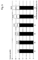
- FIG. 5 shows by way of example with which additionally available heating power is accompanied by a reduction of the district heating return temperature. For example, if the district heating return temperature is lowered from 65 ° C. to 40 ° C. by means of measures as described above for removing heat from the primary return, an increase of the heating power by, for example, 50% can be achieved.
Landscapes
- Engineering & Computer Science (AREA)
- Physics & Mathematics (AREA)
- Thermal Sciences (AREA)
- Chemical & Material Sciences (AREA)
- Combustion & Propulsion (AREA)
- Mechanical Engineering (AREA)
- General Engineering & Computer Science (AREA)
- Life Sciences & Earth Sciences (AREA)
- Sustainable Development (AREA)
- Sustainable Energy (AREA)
- Heat-Pump Type And Storage Water Heaters (AREA)
Claims (13)
- Système de canalisation (1)
avec un premier système de caloduc (2), qui présente une première extrémité (4), qui est reliable avec une station de transfert aller du réseau de téléthermie (5), et qui présente une seconde extrémité (12), qui est reliable avec une station de transfert retour du réseau de téléthermie (13), le premier système de caloduc (2) comportant un premier échangeur thermique (8) comme agent caloporteur, la première extrémité (4) du système de caloduc (2) étant reliée fluidiquement via le côté primaire de celui-ci avec la seconde extrémité (12) du système de caloduc (2), de sorte qu'un premier milieu caloporteur peut passer de la première extrémité (4) du système de caloduc (2) à la seconde extrémité (12) du système de caloduc (2), et le système de canalisation (1) comprenant par ailleurs un second système de caloduc (3), qui est isolé fluidiquement du premier système de caloduc (2),
le second système de caloduc (3) étant relié fluidiquement avec le premier échangeur thermique (8) via son côté secondaire, de sorte que le second système de caloduc (3) peut être réchauffé au moyen de chaleur provenant du premier système de caloduc (2), et
de la chaleur pouvant de nouveau être prélevée du premier milieu caloporteur dans le premier système de caloduc (2) dans une section de canalisation, qui relie côté primaire fluidiquement le premier échangeur thermique(8) avec la seconde extrémité (12) du premier système de caloduc (2), par un second échangeur thermique (15), afin de déjà réchauffer le second milieu caloporteur dans le second système de caloduc (3), avant que le second milieu caloporteur soit réchauffé par le premier échangeur thermique (8),
le second système de caloduc (3) présentant un réservoir d'accumulation de milieu caloporteur pour le second système de caloduc (3), dans lequel le second milieu caloporteur peut être réchauffé par le second échangeur thermique (15),
le premier échangeur thermique (8) étant disposé en-dehors du réservoir d'accumulation de milieu caloporteur,
caractérisé par
une pompe à jet (24) ou un mitigeur automatique, laquelle ou lequel présente deux entrées (25, 26) et une sortie (27) et est conçu pour abaisser la température du milieu caloporteur avant l'admission dans le premier échangeur thermique (8),
la première entrée (25) étant reliée fluidiquement avec la première extrémité (4) du premier système de caloduc (2),
la seconde entrée (26) étant reliée fluidiquement avec un orifice d'échappement de milieu caloporteur (10) du premier échangeur thermique (8) ou avec une section de tuyau entre le premier échangeur thermique (8) et la seconde extrémité (12) du premier système de caloduc (2), et
la sortie (27) de la pompe à jet (24) ou du mitigeur automatique aboutissant à un orifice d'arrivée de milieu caloporteur (7) du premier échangeur thermique (8). - Système de canalisation (1) selon la revendication 1, caractérisé en ce que le réservoir d'accumulation de milieu caloporteur est une citerne de milieu caloporteur.
- Système de canalisation (1) selon une quelconque des revendications précédentes, caractérisé en ce que la section de canalisation, qui relie fluidiquement le premier échangeur thermique(8) avec la seconde extrémité (12) du premier système de caloduc (2), passe à travers le réservoir d'accumulation de milieu caloporteur, afin de réchauffer le second milieu caloporteur.
- Système de canalisation (1) selon une quelconque des revendications précédentes, caractérisé en ce que le second échangeur thermique (15) est agencé côté secondaire comme réservoir d'accumulation de milieu caloporteur.
- Système de canalisation (1) selon une quelconque des revendications précédentes, caractérisé en ce qu'une liaison fluidique est présente, via laquelle le second milieu caloporteur peut être alimenté de nouveau dans le réservoir d'accumulation de milieu caloporteur, après qu'il ait été réchauffé par le premier échangeur thermique (8) et le second échangeur thermique (15).
- Système de canalisation (1) selon une quelconque des revendications précédentes, caractérisé en ce que, sur le réservoir d'accumulation de milieu caloporteur, un agent caloporteur (17, 18) est disposé, afin de transmettre au second agent caloporteur de la chaleur issue d'une source de chaleur, qui met à disposition de la chaleur en plus de la transmission de chaleur issue du premier milieu caloporteur.
- Système de canalisation (1) selon une quelconque des revendications précédentes, caractérisé en ce que la station de transfert aller du réseau de téléthermie (5) et/ou la station de transfert retour du réseau de téléthermie (13) et/ou une station de transfert de milieu caloporteur pour le second milieu caloporteur constituent une unité avec le système de canalisation (1).
- Système de canalisation (1) selon une quelconque des revendications précédentes, caractérisé en ce qu'une majorité de réservoirs d'accumulation de milieu caloporteur est présente, qui est reliée fluidiquement avec le second système de caloduc (3).
- Système de canalisation (1) selon une quelconque des revendications précédentes, caractérisé en ce que le premier milieu caloporteur est de l'eau et en ce que le second milieu caloporteur est de l'eau potable.
- Système de canalisation (1) selon une quelconque des revendications précédentes, caractérisé en ce que le système de canalisation (1) est un système de canalisation domestique.
- Procédé en vue du réchauffage d'un second milieu caloporteur d'un second système de caloduc (3) d'un système de canalisation (1), sur lequel de la chaleur résiduelle est prélevée via un second échangeur thermique (15) d'un premier milieu caloporteur, qui circule à travers un premier système de caloduc (2), afin de préchauffer le second milieu caloporteur dans un réservoir d'accumulation de milieu caloporteur, le premier milieu caloporteur ayant à ce moment déjà passé un premier échangeur thermique (8) disposé en amont dans sa trajectoire d'écoulement en vue du réchauffage du milieu de caloduc dans le second système de caloduc (3),
le premier échangeur thermique (8) étant disposé en-dehors du réservoir d'accumulation de milieu caloporteur,
le système de canalisation (1) présentant une pompe à jet (24) ou un mitigeur automatique, laquelle et/ou lequel additionne dans le premier milieu caloporteur, qui afflue dans une première extrémité (4) du premier système de caloduc (2) provenant de l'aller du réseau de téléthermie (6), du premier milieu caloporteur directement issu d'un orifice d'échappement de milieu caloporteur (10) du premier échangeur thermique (8) ou du premier milieu caloporteur issu d'un retour primaire (14) du premier système de caloduc (2) et introduit du premier milieu caloporteur à température refroidie dans le premier échangeur thermique (8). - Procédé en vue du réchauffage d'un second milieu caloporteur selon la revendication 11, caractérisé en ce que le second milieu caloporteur est réchauffé de manière supplémentaire dans le réservoir d'accumulation de milieu caloporteur par une installation à thermie solaire (17).
- Procédé en vue du réchauffage d'un second milieu caloporteur selon la revendication 12, caractérisé en ce que le second milieu caloporteur afflue d'abord dans un réservoir d'accumulation de milieu caloporteur qui est constitué par le côté secondaire d'un second échangeur thermique (15), y passe une première section du premier échangeur thermique (15), des agents caloporteurs étant disposés dans la première section en vue de transmettre de la chaleur résiduelle issue d'un premier système de caloduc (2), passe ensuite une seconde section du second échangeur thermique (15), des agents caloporteurs étant disposés dans la première section en vue de transmettre de la chaleur résiduelle issue d'une installation à thermie solaire (17), et s'écoule enfin du second échangeur thermique (15) dans un circuit de circulation (19), dans lequel le milieu caloporteur peut prélever par le premier échangeur thermique (8) de la chaleur supplémentaire issue d'un premier système de caloduc (2), qui possède une température supérieure à celle de la chaleur résiduelle qui est mise à disposition dans la première section du réservoir d'accumulation de milieu caloporteur.
Priority Applications (1)
| Application Number | Priority Date | Filing Date | Title |
|---|---|---|---|
| EP13159617.3A EP2778541B1 (fr) | 2013-03-15 | 2013-03-15 | Circuit destiné à faire baisser la température de retour primaire dans des installations de chauffage à distance |
Applications Claiming Priority (1)
| Application Number | Priority Date | Filing Date | Title |
|---|---|---|---|
| EP13159617.3A EP2778541B1 (fr) | 2013-03-15 | 2013-03-15 | Circuit destiné à faire baisser la température de retour primaire dans des installations de chauffage à distance |
Publications (2)
| Publication Number | Publication Date |
|---|---|
| EP2778541A1 EP2778541A1 (fr) | 2014-09-17 |
| EP2778541B1 true EP2778541B1 (fr) | 2016-08-24 |
Family
ID=47915468
Family Applications (1)
| Application Number | Title | Priority Date | Filing Date |
|---|---|---|---|
| EP13159617.3A Not-in-force EP2778541B1 (fr) | 2013-03-15 | 2013-03-15 | Circuit destiné à faire baisser la température de retour primaire dans des installations de chauffage à distance |
Country Status (1)
| Country | Link |
|---|---|
| EP (1) | EP2778541B1 (fr) |
Families Citing this family (2)
| Publication number | Priority date | Publication date | Assignee | Title |
|---|---|---|---|---|
| DE102021104052B3 (de) | 2021-02-19 | 2022-03-31 | Fachhochschule Westküste | Warmwasserspeicher-Beladungsverfahren an einem Fernwärmeanschluss und Warmwasser-Beladungsanordnung sowie Warmwasserbeladungs-Wärmepumpe |
| AT525350B1 (de) * | 2022-04-26 | 2023-03-15 | Theodor Ernst Seebacher | Anlage zur Wärmeversorgung eines Gebäudes |
Family Cites Families (6)
| Publication number | Priority date | Publication date | Assignee | Title |
|---|---|---|---|---|
| DE29518417U1 (de) * | 1995-10-26 | 1996-03-07 | Schidorowitz, Johann Paul, 45721 Haltern | Anlagekombination von Fernwärmeheizung und legionellenfreier Trinkwassererwärmung mit Wärmerückgewinnung für Ein- und Mehrfamilienhäusern |
| EP1403593A3 (fr) * | 2002-09-26 | 2004-05-26 | Carmelo Occhipinti | Chauffe-eau |
| DE10311091B4 (de) | 2003-03-07 | 2004-11-25 | MSR-Service für HKS-Anlagen Öl- und Gasbrenner GmbH | Verfahren und Einrichtung zur Reduzierung des Anschlusswertes einer durch Fernwärme gespeisten Hausanschlussstation |
| DE102005044845A1 (de) * | 2005-09-20 | 2007-03-22 | Gewofag Gemeinnützige Wohnungsfürsorge AG | Trinkwassererwärmungsanlage |
| DE202006018246U1 (de) * | 2006-12-01 | 2007-06-06 | Nestke, Carla, Dipl.-Ing. | Zusatzbauteil zur Regelung von Warmwasserbereitungsanlagen |
| DE102008057908A1 (de) | 2008-11-18 | 2010-05-20 | Swm Services Gmbh | Wärmeübergabestation mit Kaskade |
-
2013
- 2013-03-15 EP EP13159617.3A patent/EP2778541B1/fr not_active Not-in-force
Also Published As
| Publication number | Publication date |
|---|---|
| EP2778541A1 (fr) | 2014-09-17 |
Similar Documents
| Publication | Publication Date | Title |
|---|---|---|
| AT412818B (de) | Heiz- und warmwasserbereitungsanlage und verfahren zum betrieb einer solchen anlage | |
| DE102009047908B4 (de) | Vorrichtung und Verfahren zur Versorgung eines kalten Nahwärmenetzes mit Wärme | |
| DE202009006988U1 (de) | Warmwasserversorgungsanlage mit einem Warmwasserspeicher | |
| EP3705789B1 (fr) | Système d'alimentation en eau et son procédé de fonctionnement | |
| DE102008033063B4 (de) | Verfahren und Vorrichtung zur zentralen Warmwasserversorgung | |
| EP1447627B1 (fr) | Dispositif de commande et/ou contrôle d'un chauffage ou d'un refroidissement d'un immeuble | |
| EP2218970B1 (fr) | Système d'équilibrage des températures | |
| EP3617601B1 (fr) | Système d'eau chaude, en particulier installation de chauffage d'eau potable et de conduites d'eau potable | |
| DE19504730C1 (de) | Warmwasserbereitungsanlage nach dem Durchflußprinzip mit Leistungsbegrenzung | |
| EP2778541A1 (fr) | Circuit destiné à faire baisser la température de retour primaire dans des installations de chauffage à distance | |
| EP1371910B1 (fr) | Station de raccordement domestique pour chauffage à distance | |
| EP2226571B1 (fr) | Agencement et procédé de chauffage d'eau potable pour un site de consommation, respectivement, de distribution | |
| EP0141339B1 (fr) | Dispositif pour la récupération de la chaleur des eaux usées avec économie simultanée d'eau potable | |
| EP2339245A2 (fr) | Dispositifs de chauffage et de refroidissement dotés d'une pompe à chaleur | |
| DE102015118826A1 (de) | Anordnung und Verfahren zur Bereitstellung von warmem Trinkwasser mit einem Wärmeübertrager | |
| DE19707859A1 (de) | Anordnung zur Übertragung von Wärmeenergie | |
| EP2778540B1 (fr) | Procédé et dispositif de chauffage de bâtiments par chauffage à infrarouge | |
| DE102005007452A1 (de) | Vorrichtung zur thermischen Desinfektion von Trinkwarmwasserversorgungsanlagen | |
| DE3230371C1 (de) | Wärmepumpenheizung | |
| EP4105396B1 (fr) | Système d'eau potable et d'eau sanitaire | |
| WO2003074941A1 (fr) | Echangeur thermique et dispositif de recuperation de l'energie thermique accumulee dans les eaux usees d'un batiment | |
| DE102022127744B4 (de) | Zentralheizungssystem und Verfahren zum Betrieb und/oder zur Steuerung und/oder zur Regelung eines Zentralheizungssystems | |
| DE102007009198B4 (de) | Wasserspeicher | |
| EP4269882A1 (fr) | Système d'alimentation en eau chaude avec récupération de chaleur | |
| DE3047742A1 (de) | Vorrichtung zum erwaermen von brauchwasser |
Legal Events
| Date | Code | Title | Description |
|---|---|---|---|
| PUAI | Public reference made under article 153(3) epc to a published international application that has entered the european phase |
Free format text: ORIGINAL CODE: 0009012 |
|
| 17P | Request for examination filed |
Effective date: 20130315 |
|
| AK | Designated contracting states |
Kind code of ref document: A1 Designated state(s): AL AT BE BG CH CY CZ DE DK EE ES FI FR GB GR HR HU IE IS IT LI LT LU LV MC MK MT NL NO PL PT RO RS SE SI SK SM TR |
|
| AX | Request for extension of the european patent |
Extension state: BA ME |
|
| R17P | Request for examination filed (corrected) |
Effective date: 20150312 |
|
| RBV | Designated contracting states (corrected) |
Designated state(s): AL AT BE BG CH CY CZ DE DK EE ES FI FR GB GR HR HU IE IS IT LI LT LU LV MC MK MT NL NO PL PT RO RS SE SI SK SM TR |
|
| 17Q | First examination report despatched |
Effective date: 20150714 |
|
| GRAP | Despatch of communication of intention to grant a patent |
Free format text: ORIGINAL CODE: EPIDOSNIGR1 |
|
| INTG | Intention to grant announced |
Effective date: 20160302 |
|
| GRAS | Grant fee paid |
Free format text: ORIGINAL CODE: EPIDOSNIGR3 |
|
| GRAA | (expected) grant |
Free format text: ORIGINAL CODE: 0009210 |
|
| AK | Designated contracting states |
Kind code of ref document: B1 Designated state(s): AL AT BE BG CH CY CZ DE DK EE ES FI FR GB GR HR HU IE IS IT LI LT LU LV MC MK MT NL NO PL PT RO RS SE SI SK SM TR |
|
| REG | Reference to a national code |
Ref country code: GB Ref legal event code: FG4D Free format text: NOT ENGLISH |
|
| REG | Reference to a national code |
Ref country code: CH Ref legal event code: EP |
|
| REG | Reference to a national code |
Ref country code: AT Ref legal event code: REF Ref document number: 823460 Country of ref document: AT Kind code of ref document: T Effective date: 20160915 |
|
| REG | Reference to a national code |
Ref country code: IE Ref legal event code: FG4D Free format text: LANGUAGE OF EP DOCUMENT: GERMAN |
|
| REG | Reference to a national code |
Ref country code: DE Ref legal event code: R096 Ref document number: 502013004117 Country of ref document: DE |
|
| REG | Reference to a national code |
Ref country code: CH Ref legal event code: NV Representative=s name: MEYERLUSTENBERGER LACHENAL, CH |
|
| REG | Reference to a national code |
Ref country code: LT Ref legal event code: MG4D |
|
| REG | Reference to a national code |
Ref country code: NL Ref legal event code: MP Effective date: 20160824 |
|
| PG25 | Lapsed in a contracting state [announced via postgrant information from national office to epo] |
Ref country code: RS Free format text: LAPSE BECAUSE OF FAILURE TO SUBMIT A TRANSLATION OF THE DESCRIPTION OR TO PAY THE FEE WITHIN THE PRESCRIBED TIME-LIMIT Effective date: 20160824 Ref country code: NL Free format text: LAPSE BECAUSE OF FAILURE TO SUBMIT A TRANSLATION OF THE DESCRIPTION OR TO PAY THE FEE WITHIN THE PRESCRIBED TIME-LIMIT Effective date: 20160824 Ref country code: FI Free format text: LAPSE BECAUSE OF FAILURE TO SUBMIT A TRANSLATION OF THE DESCRIPTION OR TO PAY THE FEE WITHIN THE PRESCRIBED TIME-LIMIT Effective date: 20160824 Ref country code: NO Free format text: LAPSE BECAUSE OF FAILURE TO SUBMIT A TRANSLATION OF THE DESCRIPTION OR TO PAY THE FEE WITHIN THE PRESCRIBED TIME-LIMIT Effective date: 20161124 Ref country code: IT Free format text: LAPSE BECAUSE OF FAILURE TO SUBMIT A TRANSLATION OF THE DESCRIPTION OR TO PAY THE FEE WITHIN THE PRESCRIBED TIME-LIMIT Effective date: 20160824 Ref country code: HR Free format text: LAPSE BECAUSE OF FAILURE TO SUBMIT A TRANSLATION OF THE DESCRIPTION OR TO PAY THE FEE WITHIN THE PRESCRIBED TIME-LIMIT Effective date: 20160824 Ref country code: LT Free format text: LAPSE BECAUSE OF FAILURE TO SUBMIT A TRANSLATION OF THE DESCRIPTION OR TO PAY THE FEE WITHIN THE PRESCRIBED TIME-LIMIT Effective date: 20160824 |
|
| PG25 | Lapsed in a contracting state [announced via postgrant information from national office to epo] |
Ref country code: LV Free format text: LAPSE BECAUSE OF FAILURE TO SUBMIT A TRANSLATION OF THE DESCRIPTION OR TO PAY THE FEE WITHIN THE PRESCRIBED TIME-LIMIT Effective date: 20160824 Ref country code: GR Free format text: LAPSE BECAUSE OF FAILURE TO SUBMIT A TRANSLATION OF THE DESCRIPTION OR TO PAY THE FEE WITHIN THE PRESCRIBED TIME-LIMIT Effective date: 20161125 Ref country code: PT Free format text: LAPSE BECAUSE OF FAILURE TO SUBMIT A TRANSLATION OF THE DESCRIPTION OR TO PAY THE FEE WITHIN THE PRESCRIBED TIME-LIMIT Effective date: 20161226 Ref country code: SE Free format text: LAPSE BECAUSE OF FAILURE TO SUBMIT A TRANSLATION OF THE DESCRIPTION OR TO PAY THE FEE WITHIN THE PRESCRIBED TIME-LIMIT Effective date: 20160824 Ref country code: ES Free format text: LAPSE BECAUSE OF FAILURE TO SUBMIT A TRANSLATION OF THE DESCRIPTION OR TO PAY THE FEE WITHIN THE PRESCRIBED TIME-LIMIT Effective date: 20160824 |
|
| REG | Reference to a national code |
Ref country code: FR Ref legal event code: PLFP Year of fee payment: 5 |
|
| PG25 | Lapsed in a contracting state [announced via postgrant information from national office to epo] |
Ref country code: EE Free format text: LAPSE BECAUSE OF FAILURE TO SUBMIT A TRANSLATION OF THE DESCRIPTION OR TO PAY THE FEE WITHIN THE PRESCRIBED TIME-LIMIT Effective date: 20160824 Ref country code: RO Free format text: LAPSE BECAUSE OF FAILURE TO SUBMIT A TRANSLATION OF THE DESCRIPTION OR TO PAY THE FEE WITHIN THE PRESCRIBED TIME-LIMIT Effective date: 20160824 |
|
| REG | Reference to a national code |
Ref country code: DE Ref legal event code: R097 Ref document number: 502013004117 Country of ref document: DE |
|
| PG25 | Lapsed in a contracting state [announced via postgrant information from national office to epo] |
Ref country code: BG Free format text: LAPSE BECAUSE OF FAILURE TO SUBMIT A TRANSLATION OF THE DESCRIPTION OR TO PAY THE FEE WITHIN THE PRESCRIBED TIME-LIMIT Effective date: 20161124 Ref country code: CZ Free format text: LAPSE BECAUSE OF FAILURE TO SUBMIT A TRANSLATION OF THE DESCRIPTION OR TO PAY THE FEE WITHIN THE PRESCRIBED TIME-LIMIT Effective date: 20160824 Ref country code: DK Free format text: LAPSE BECAUSE OF FAILURE TO SUBMIT A TRANSLATION OF THE DESCRIPTION OR TO PAY THE FEE WITHIN THE PRESCRIBED TIME-LIMIT Effective date: 20160824 Ref country code: SK Free format text: LAPSE BECAUSE OF FAILURE TO SUBMIT A TRANSLATION OF THE DESCRIPTION OR TO PAY THE FEE WITHIN THE PRESCRIBED TIME-LIMIT Effective date: 20160824 Ref country code: PL Free format text: LAPSE BECAUSE OF FAILURE TO SUBMIT A TRANSLATION OF THE DESCRIPTION OR TO PAY THE FEE WITHIN THE PRESCRIBED TIME-LIMIT Effective date: 20160824 Ref country code: SM Free format text: LAPSE BECAUSE OF FAILURE TO SUBMIT A TRANSLATION OF THE DESCRIPTION OR TO PAY THE FEE WITHIN THE PRESCRIBED TIME-LIMIT Effective date: 20160824 |
|
| PLBE | No opposition filed within time limit |
Free format text: ORIGINAL CODE: 0009261 |
|
| STAA | Information on the status of an ep patent application or granted ep patent |
Free format text: STATUS: NO OPPOSITION FILED WITHIN TIME LIMIT |
|
| 26N | No opposition filed |
Effective date: 20170526 |
|
| PG25 | Lapsed in a contracting state [announced via postgrant information from national office to epo] |
Ref country code: SI Free format text: LAPSE BECAUSE OF FAILURE TO SUBMIT A TRANSLATION OF THE DESCRIPTION OR TO PAY THE FEE WITHIN THE PRESCRIBED TIME-LIMIT Effective date: 20160824 |
|
| REG | Reference to a national code |
Ref country code: CH Ref legal event code: PFA Owner name: GEWOFAG GEBAEUDE SERVICE GMBH, DE Free format text: FORMER OWNER: GEWOFAG GEBAEUDE SERVICE GMBH, DE |
|
| REG | Reference to a national code |
Ref country code: BE Ref legal event code: MM Effective date: 20170331 |
|
| REG | Reference to a national code |
Ref country code: FR Ref legal event code: PLFP Year of fee payment: 6 |
|
| PG25 | Lapsed in a contracting state [announced via postgrant information from national office to epo] |
Ref country code: BE Free format text: LAPSE BECAUSE OF NON-PAYMENT OF DUE FEES Effective date: 20170331 |
|
| PG25 | Lapsed in a contracting state [announced via postgrant information from national office to epo] |
Ref country code: MT Free format text: LAPSE BECAUSE OF FAILURE TO SUBMIT A TRANSLATION OF THE DESCRIPTION OR TO PAY THE FEE WITHIN THE PRESCRIBED TIME-LIMIT Effective date: 20160824 |
|
| PG25 | Lapsed in a contracting state [announced via postgrant information from national office to epo] |
Ref country code: AL Free format text: LAPSE BECAUSE OF FAILURE TO SUBMIT A TRANSLATION OF THE DESCRIPTION OR TO PAY THE FEE WITHIN THE PRESCRIBED TIME-LIMIT Effective date: 20160824 |
|
| PGFP | Annual fee paid to national office [announced via postgrant information from national office to epo] |
Ref country code: CH Payment date: 20190325 Year of fee payment: 7 Ref country code: MC Payment date: 20190320 Year of fee payment: 7 Ref country code: IE Payment date: 20190326 Year of fee payment: 7 Ref country code: DE Payment date: 20190325 Year of fee payment: 7 Ref country code: LU Payment date: 20190321 Year of fee payment: 7 Ref country code: FR Payment date: 20190326 Year of fee payment: 7 Ref country code: GB Payment date: 20190325 Year of fee payment: 7 |
|
| REG | Reference to a national code |
Ref country code: AT Ref legal event code: MM01 Ref document number: 823460 Country of ref document: AT Kind code of ref document: T Effective date: 20180315 |
|
| PG25 | Lapsed in a contracting state [announced via postgrant information from national office to epo] |
Ref country code: HU Free format text: LAPSE BECAUSE OF FAILURE TO SUBMIT A TRANSLATION OF THE DESCRIPTION OR TO PAY THE FEE WITHIN THE PRESCRIBED TIME-LIMIT; INVALID AB INITIO Effective date: 20130315 |
|
| PG25 | Lapsed in a contracting state [announced via postgrant information from national office to epo] |
Ref country code: CY Free format text: LAPSE BECAUSE OF NON-PAYMENT OF DUE FEES Effective date: 20160824 Ref country code: AT Free format text: LAPSE BECAUSE OF NON-PAYMENT OF DUE FEES Effective date: 20180315 |
|
| PG25 | Lapsed in a contracting state [announced via postgrant information from national office to epo] |
Ref country code: MK Free format text: LAPSE BECAUSE OF FAILURE TO SUBMIT A TRANSLATION OF THE DESCRIPTION OR TO PAY THE FEE WITHIN THE PRESCRIBED TIME-LIMIT Effective date: 20160824 |
|
| PG25 | Lapsed in a contracting state [announced via postgrant information from national office to epo] |
Ref country code: TR Free format text: LAPSE BECAUSE OF FAILURE TO SUBMIT A TRANSLATION OF THE DESCRIPTION OR TO PAY THE FEE WITHIN THE PRESCRIBED TIME-LIMIT Effective date: 20160824 |
|
| PG25 | Lapsed in a contracting state [announced via postgrant information from national office to epo] |
Ref country code: IS Free format text: LAPSE BECAUSE OF FAILURE TO SUBMIT A TRANSLATION OF THE DESCRIPTION OR TO PAY THE FEE WITHIN THE PRESCRIBED TIME-LIMIT Effective date: 20161224 |
|
| REG | Reference to a national code |
Ref country code: DE Ref legal event code: R119 Ref document number: 502013004117 Country of ref document: DE |
|
| PG25 | Lapsed in a contracting state [announced via postgrant information from national office to epo] |
Ref country code: MC Free format text: LAPSE BECAUSE OF NON-PAYMENT OF DUE FEES Effective date: 20200331 |
|
| REG | Reference to a national code |
Ref country code: CH Ref legal event code: PL |
|
| PG25 | Lapsed in a contracting state [announced via postgrant information from national office to epo] |
Ref country code: LU Free format text: LAPSE BECAUSE OF NON-PAYMENT OF DUE FEES Effective date: 20200315 |
|
| PG25 | Lapsed in a contracting state [announced via postgrant information from national office to epo] |
Ref country code: CH Free format text: LAPSE BECAUSE OF NON-PAYMENT OF DUE FEES Effective date: 20200331 Ref country code: IE Free format text: LAPSE BECAUSE OF NON-PAYMENT OF DUE FEES Effective date: 20200315 Ref country code: DE Free format text: LAPSE BECAUSE OF NON-PAYMENT OF DUE FEES Effective date: 20201001 Ref country code: LI Free format text: LAPSE BECAUSE OF NON-PAYMENT OF DUE FEES Effective date: 20200331 Ref country code: FR Free format text: LAPSE BECAUSE OF NON-PAYMENT OF DUE FEES Effective date: 20200331 |
|
| GBPC | Gb: european patent ceased through non-payment of renewal fee |
Effective date: 20200315 |
|
| PG25 | Lapsed in a contracting state [announced via postgrant information from national office to epo] |
Ref country code: GB Free format text: LAPSE BECAUSE OF NON-PAYMENT OF DUE FEES Effective date: 20200315 |