EP2778564A2 - Tôle support - Google Patents
Tôle support Download PDFInfo
- Publication number
- EP2778564A2 EP2778564A2 EP14000640.4A EP14000640A EP2778564A2 EP 2778564 A2 EP2778564 A2 EP 2778564A2 EP 14000640 A EP14000640 A EP 14000640A EP 2778564 A2 EP2778564 A2 EP 2778564A2
- Authority
- EP
- European Patent Office
- Prior art keywords
- tube
- support plate
- wall sections
- wall
- maximum distance
- Prior art date
- Legal status (The legal status is an assumption and is not a legal conclusion. Google has not performed a legal analysis and makes no representation as to the accuracy of the status listed.)
- Withdrawn
Links
- 229910052751 metal Inorganic materials 0.000 title description 6
- 239000002184 metal Substances 0.000 title description 6
- 238000000034 method Methods 0.000 claims abstract description 24
- 238000004519 manufacturing process Methods 0.000 claims abstract description 7
- 239000006096 absorbing agent Substances 0.000 description 21
- 238000010276 construction Methods 0.000 description 9
- 239000000853 adhesive Substances 0.000 description 5
- 230000001070 adhesive effect Effects 0.000 description 5
- 238000010438 heat treatment Methods 0.000 description 5
- 238000010521 absorption reaction Methods 0.000 description 4
- 238000001816 cooling Methods 0.000 description 4
- 239000000463 material Substances 0.000 description 4
- 230000005855 radiation Effects 0.000 description 4
- 230000035882 stress Effects 0.000 description 4
- RYGMFSIKBFXOCR-UHFFFAOYSA-N Copper Chemical compound [Cu] RYGMFSIKBFXOCR-UHFFFAOYSA-N 0.000 description 3
- 229910052782 aluminium Inorganic materials 0.000 description 3
- XAGFODPZIPBFFR-UHFFFAOYSA-N aluminium Chemical compound [Al] XAGFODPZIPBFFR-UHFFFAOYSA-N 0.000 description 3
- 230000008602 contraction Effects 0.000 description 3
- 229910052802 copper Inorganic materials 0.000 description 3
- 239000010949 copper Substances 0.000 description 3
- 238000009420 retrofitting Methods 0.000 description 3
- 238000005476 soldering Methods 0.000 description 3
- 238000003466 welding Methods 0.000 description 3
- 229910000838 Al alloy Inorganic materials 0.000 description 2
- 244000089486 Phragmites australis subsp australis Species 0.000 description 2
- 238000004026 adhesive bonding Methods 0.000 description 2
- 230000005489 elastic deformation Effects 0.000 description 2
- 238000005304 joining Methods 0.000 description 2
- 229910000881 Cu alloy Inorganic materials 0.000 description 1
- 230000002745 absorbent Effects 0.000 description 1
- 239000002250 absorbent Substances 0.000 description 1
- 230000015572 biosynthetic process Effects 0.000 description 1
- 238000006243 chemical reaction Methods 0.000 description 1
- 238000005520 cutting process Methods 0.000 description 1
- 230000001419 dependent effect Effects 0.000 description 1
- 229920001971 elastomer Polymers 0.000 description 1
- 239000000806 elastomer Substances 0.000 description 1
- 238000005516 engineering process Methods 0.000 description 1
- 230000001747 exhibiting effect Effects 0.000 description 1
- 230000002349 favourable effect Effects 0.000 description 1
- 239000004519 grease Substances 0.000 description 1
- 230000017525 heat dissipation Effects 0.000 description 1
- 150000002739 metals Chemical class 0.000 description 1
- 238000004080 punching Methods 0.000 description 1
- 229910000679 solder Inorganic materials 0.000 description 1
- 239000000725 suspension Substances 0.000 description 1
- 230000008646 thermal stress Effects 0.000 description 1
Images



Classifications
-
- F—MECHANICAL ENGINEERING; LIGHTING; HEATING; WEAPONS; BLASTING
- F28—HEAT EXCHANGE IN GENERAL
- F28F—DETAILS OF HEAT-EXCHANGE AND HEAT-TRANSFER APPARATUS, OF GENERAL APPLICATION
- F28F1/00—Tubular elements; Assemblies of tubular elements
- F28F1/10—Tubular elements and assemblies thereof with means for increasing heat-transfer area, e.g. with fins, with projections, with recesses
- F28F1/12—Tubular elements and assemblies thereof with means for increasing heat-transfer area, e.g. with fins, with projections, with recesses the means being only outside the tubular element
- F28F1/14—Tubular elements and assemblies thereof with means for increasing heat-transfer area, e.g. with fins, with projections, with recesses the means being only outside the tubular element and extending longitudinally
- F28F1/22—Tubular elements and assemblies thereof with means for increasing heat-transfer area, e.g. with fins, with projections, with recesses the means being only outside the tubular element and extending longitudinally the means having portions engaging further tubular elements
-
- B—PERFORMING OPERATIONS; TRANSPORTING
- B21—MECHANICAL METAL-WORKING WITHOUT ESSENTIALLY REMOVING MATERIAL; PUNCHING METAL
- B21D—WORKING OR PROCESSING OF SHEET METAL OR METAL TUBES, RODS OR PROFILES WITHOUT ESSENTIALLY REMOVING MATERIAL; PUNCHING METAL
- B21D53/00—Making other particular articles
- B21D53/02—Making other particular articles heat exchangers or parts thereof, e.g. radiators, condensers fins, headers
- B21D53/08—Making other particular articles heat exchangers or parts thereof, e.g. radiators, condensers fins, headers of both metal tubes and sheet metal
-
- F—MECHANICAL ENGINEERING; LIGHTING; HEATING; WEAPONS; BLASTING
- F24—HEATING; RANGES; VENTILATING
- F24S—SOLAR HEAT COLLECTORS; SOLAR HEAT SYSTEMS
- F24S10/00—Solar heat collectors using working fluids
- F24S10/70—Solar heat collectors using working fluids the working fluids being conveyed through tubular absorbing conduits
- F24S10/75—Solar heat collectors using working fluids the working fluids being conveyed through tubular absorbing conduits with enlarged surfaces, e.g. with protrusions or corrugations
-
- F—MECHANICAL ENGINEERING; LIGHTING; HEATING; WEAPONS; BLASTING
- F24—HEATING; RANGES; VENTILATING
- F24S—SOLAR HEAT COLLECTORS; SOLAR HEAT SYSTEMS
- F24S10/00—Solar heat collectors using working fluids
- F24S10/70—Solar heat collectors using working fluids the working fluids being conveyed through tubular absorbing conduits
- F24S10/75—Solar heat collectors using working fluids the working fluids being conveyed through tubular absorbing conduits with enlarged surfaces, e.g. with protrusions or corrugations
- F24S10/755—Solar heat collectors using working fluids the working fluids being conveyed through tubular absorbing conduits with enlarged surfaces, e.g. with protrusions or corrugations the conduits being otherwise bent, e.g. zig-zag
-
- F—MECHANICAL ENGINEERING; LIGHTING; HEATING; WEAPONS; BLASTING
- F24—HEATING; RANGES; VENTILATING
- F24S—SOLAR HEAT COLLECTORS; SOLAR HEAT SYSTEMS
- F24S40/00—Safety or protection arrangements of solar heat collectors; Preventing malfunction of solar heat collectors
- F24S40/80—Accommodating differential expansion of solar collector elements
-
- F—MECHANICAL ENGINEERING; LIGHTING; HEATING; WEAPONS; BLASTING
- F28—HEAT EXCHANGE IN GENERAL
- F28D—HEAT-EXCHANGE APPARATUS, NOT PROVIDED FOR IN ANOTHER SUBCLASS, IN WHICH THE HEAT-EXCHANGE MEDIA DO NOT COME INTO DIRECT CONTACT
- F28D1/00—Heat-exchange apparatus having stationary conduit assemblies for one heat-exchange medium only, the media being in contact with different sides of the conduit wall, in which the other heat-exchange medium is a large body of fluid, e.g. domestic or motor car radiators
- F28D1/02—Heat-exchange apparatus having stationary conduit assemblies for one heat-exchange medium only, the media being in contact with different sides of the conduit wall, in which the other heat-exchange medium is a large body of fluid, e.g. domestic or motor car radiators with heat-exchange conduits immersed in the body of fluid
- F28D1/04—Heat-exchange apparatus having stationary conduit assemblies for one heat-exchange medium only, the media being in contact with different sides of the conduit wall, in which the other heat-exchange medium is a large body of fluid, e.g. domestic or motor car radiators with heat-exchange conduits immersed in the body of fluid with tubular conduits
-
- F—MECHANICAL ENGINEERING; LIGHTING; HEATING; WEAPONS; BLASTING
- F28—HEAT EXCHANGE IN GENERAL
- F28D—HEAT-EXCHANGE APPARATUS, NOT PROVIDED FOR IN ANOTHER SUBCLASS, IN WHICH THE HEAT-EXCHANGE MEDIA DO NOT COME INTO DIRECT CONTACT
- F28D1/00—Heat-exchange apparatus having stationary conduit assemblies for one heat-exchange medium only, the media being in contact with different sides of the conduit wall, in which the other heat-exchange medium is a large body of fluid, e.g. domestic or motor car radiators
- F28D1/02—Heat-exchange apparatus having stationary conduit assemblies for one heat-exchange medium only, the media being in contact with different sides of the conduit wall, in which the other heat-exchange medium is a large body of fluid, e.g. domestic or motor car radiators with heat-exchange conduits immersed in the body of fluid
- F28D2001/0253—Particular components
- F28D2001/0286—Radiating plates; Decorative panels
- F28D2001/0293—Radiating plates; Decorative panels with grooves for integration of conduits
-
- F—MECHANICAL ENGINEERING; LIGHTING; HEATING; WEAPONS; BLASTING
- F28—HEAT EXCHANGE IN GENERAL
- F28F—DETAILS OF HEAT-EXCHANGE AND HEAT-TRANSFER APPARATUS, OF GENERAL APPLICATION
- F28F2265/00—Safety or protection arrangements; Arrangements for preventing malfunction
- F28F2265/26—Safety or protection arrangements; Arrangements for preventing malfunction for allowing differential expansion between elements
-
- Y—GENERAL TAGGING OF NEW TECHNOLOGICAL DEVELOPMENTS; GENERAL TAGGING OF CROSS-SECTIONAL TECHNOLOGIES SPANNING OVER SEVERAL SECTIONS OF THE IPC; TECHNICAL SUBJECTS COVERED BY FORMER USPC CROSS-REFERENCE ART COLLECTIONS [XRACs] AND DIGESTS
- Y02—TECHNOLOGIES OR APPLICATIONS FOR MITIGATION OR ADAPTATION AGAINST CLIMATE CHANGE
- Y02E—REDUCTION OF GREENHOUSE GAS [GHG] EMISSIONS, RELATED TO ENERGY GENERATION, TRANSMISSION OR DISTRIBUTION
- Y02E10/00—Energy generation through renewable energy sources
- Y02E10/40—Solar thermal energy, e.g. solar towers
- Y02E10/44—Heat exchange systems
Definitions
- the present invention relates to a support plate with at least two molded into the support plate, channel-shaped and spaced apart tube receptacles for positive reception of a respective tube, the respective tube receiving, seen in a cross section, at least two opposing wall sections of the support plate to rest on the pipe, and the wall portions for a range of a maximum outer diameter of the tube have their maximum distance from each other.
- thermal solar technology such arrangements are used in particular in the construction of solar collectors.
- the solar radiation is, as is known, absorbed by so-called absorber plates.
- These are usually coated on the sunny side and connected on the side facing away from the sun side with pipes through which a heat transfer medium flows for heat removal.
- From prior public use arrangements are known in which the tubes are directly connected by soldering or welding to the absorbent plate.
- a disadvantage of such arrangements is that due to thermal expansions large mechanical stresses can occur in the connection between the tube and the absorber plate, which under certain circumstances can lead to a loosening of the connection.
- the heat transfer surface is limited due to the linear formation of the weld or solder seam.
- thermal solar collectors and so-called hybrid collectors are known in the art.
- the object of the invention is to provide an improved embodiment of a carrier plate of the type mentioned, which is simple in construction and provides a good heat transfer.
- the invention solves this problem by a carrier plate of the type mentioned above, wherein it is provided that on at least two opposite sides of the maximum distance, the wall portions each have a smaller distance than the maximum distance from each other.
- all three distances are measured parallel to each other. It is particularly preferable if the distances are measured parallel to the plane of the regions of the carrier sheet surrounding the tube receiving means.
- the material of the carrier sheet is preferably a metal sheet with good thermal conductivity, for. As aluminum or copper.
- the support plate made of aluminum, or an aluminum alloy.
- the wall portions of the respective pipe receiving symmetrically, preferably axially symmetrically, are arranged to each other.
- Preferred embodiments of the carrier sheet provide that at least one of the wall sections, seen in a cross-section, is part of a loop, wherein the loop has two legs interconnected by a bent portion, and one of the two legs is the wall section.
- the tube in the sense of resilient suspension is held with the loop or in the loops in the pipe receiving.
- the heating or cooling of the support plate, or the surrounding construction thermally induced expansion or contraction of the construction can be compensated by the elastic deformation of the loops.
- thermally generated voltage in the tube or in the connection between the tube and the support plate is prevented or at least significantly reduced.
- the thermally induced changes in length which occur can be compensated locally with such a loop arrangement without generating high mechanical stresses which would otherwise accumulate over the entire length of the carrier plate.
- the loop could also be called a loop. It has at least two legs, which are connected to each other by means of the bent portion.
- the bent-over region of the loops has an angle of greater than 180 °.
- the legs of the loop are spaced from each other. This ensures that the loop construction can deform sufficiently to compensate for the thermally induced expansion or the thermally induced contraction of the support plate or the tube locally.
- the cross section of the wall sections of the respective pipe receiving can be different depending on preparatordem pipe cross section. It can be rectangular, polygonal, oval or other cross sections. It is advantageously provided that the wall sections of the respective pipe receiving at least partially have a circular cross-section and extend together, preferably without interruption, by more than 180 ° in the circumferential direction of the circular cross-section to rest on the pipe. It is then ensured that a can be introduced into the support plate tube with a circular cross-section over wide areas of its circumference in the direction normal to the longitudinal extent of the tube can be held positively. In terms of a good heat transfer between the support plate and the tube to be introduced is preferably provided that the tube rests with its lateral surface over the entire surface of the wall portions of the respective pipe receiving.
- a sectional area is referred to, which is normal to the longitudinal extent of the pipe receiving.
- Preferred embodiments of the invention provide that there is an opening for introducing the pipe into the pipe receiving device between the wall sections of the pipe receiving device, preferably on a side facing away from the regions of the carrier sheet surrounding the pipe receiving device.
- the invention also provides an arrangement with a carrier sheet according to the invention and at least one tube, wherein the tube is held in a form-fitting manner in at least one of the tube receptacles of the support plate of the wall sections.
- the pipe in the pipe receptacle may be a single pipe or a pipe section. It is conceivable and possible in this context that a single tube is held in a form-fitting manner in a respective tube receiving the carrier sheet, and these are connected to each other in parallel via a collecting tube, in the sense of a register or a harp. Preferred embodiments of the arrangement provide that the at least one, preferably meander-shaped, tube is held in a form-fitting manner by the respective wall sections in at least two of the tube receptacles of the carrier plate.
- a single meander-shaped tube is held in a form-fitting manner by the respective wall sections in all tube receptacles of the carrier plate.
- the tube is a metallic tube, preferably the tube is copper or a copper alloy. The use of other suitable materials is possible.
- the tube receptacles of the carrier plate are generally aligned parallel to one another. However, it is also conceivable that the tube receptacles are positioned at an arbitrary angle to each other in the support plate.
- the arrangement has a rear wall, and the carrier sheet in the region of at least two tube receptacles, preferably adhered to the protruding from the surrounding region of the support plate ends of the tube receiving, bonded to the rear wall or otherwise, preferably materially connected , It is advantageously provided that it is at the protruding ends of the pipe receiving the Umbiege Schl the loops. It is particularly preferred if the adhesive is introduced in the region of the opening between the wall sections or loops and the support plate is glued to the rear wall via these splices. The adhesive may be in this context known per se and commercially available adhesives. This arrangement is particularly suitable for retrofitting photovoltaic modules to improve their efficiency by cooling.
- the invention further provides a method for producing an arrangement according to the invention with a carrier plate and at least one tube, wherein in a first forming process for producing the at least two molded, channel-shaped and spaced-apart tube receptacles, parts of the respective at least two opposing wall sections in the carrier sheet Forming of the support plate are formed, subsequently the respective tube between these parts of the wall sections is introduced, and in a second forming process, the support plate for the completion of the wall sections is further deformed, wherein the wall sections at the end of the second forming operation for the range of the maximum outer diameter of the Pipe, their maximum distance from each other, wherein on at least the two opposite sides of the maximum distance, the wall portions each have the smaller distance than the maximum distance from each other a uf mars.
- parts of the wall sections are formed in a first forming process in the support plate.
- the width of the opening is preferably so large after the first forming process that the tube can be introduced into the tube receiving device configured as far as possible.
- the wall sections are further deformed so that the tube is held in a form-fitting manner between them.
- the arrangement for heat dissipation for example as surface heating, or to use for heat absorption.
- an application as wall heating or underfloor heating is conceivable.
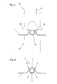
- Fig. 1 is a section through an inventive arrangement shown.
- an inventive carrier sheet 1 with three molded, channel-shaped and spaced apart tube receptacles 2 for positive reception of each tube 20. Between the tube receptacles 2 is in each case a surrounding area 10 of the support plate 1.
- the surrounding areas 10 are preferably flat.
- the material of the carrier sheet is preferably metal, preferably copper, aluminum or aluminum alloys. Other metals with corresponding thermal conductivity can be used.
- the cross section of the tube could also be different, z. B. rectangular, in the form of a polygon, oval or have any free-form.
- As a cross-section in this context is called the cutting surface, which is arranged normal to the longitudinal extent of the pipe receiving.
- the Fig. 2 shows the enlarged area B of Fig. 1 ,
- the positive reception of a tube 20 in the tube holder 2 is clearly visible.
- the wall sections 3 and 4 are each part of a loop 5, the loop 5 has two connected by a bent portion 6 leg 3, 4, 14, and one of the two legs 3, 4, 14 of the wall portion 3 and 4 respectively.
- the tube 20 is held by the carrier sheet 1 according to the invention over large parts of its circumference in the direction orthogonal to the longitudinal extent of the tube receiving 2 in this form-fitting manner between the two wall sections 3 and 4 of the tube holder.
- the wall sections 3, 4 for a range of maximum outer diameter of the tube 20 have their maximum distance 21 from each other and on two opposite sides of the maximum distance 21, the wall sections 3, 4 each have a smaller distance 11, 12 than the maximum distance 21 from each other.
- the distances mentioned are preferably measured parallel to each other.
- the aforementioned distances 11, 12, 21 particularly preferably parallel to the reference plane 13 of the regions 10 of the tube receptacles 2 surrounding Carrier sheet 1 are measured.
- the reference plane 13 deviates from the surrounding regions 10 of the carrier sheet 1.
- Fig. 2 is also very well seen that the wall sections 3 and 4 of the tube holder 2 in this embodiment symmetrically, are arranged here axially symmetrical to each other.
- the cross section of the tube 20 introduced here is a circular cross section.
- the wall sections 3, 4 of the tube holder 2 have at least partially in this embodiment, a circular cross-section and extend together, preferably without interruption, by more than 180 ° in the circumferential direction of the circular cross-section to rest on the pipe.
- a large contact surface for heat transfer from the support plate 1 to the tube 20 and vice versa is achieved. It is conceivable and possible to increase the facility on the pipe up to 360 ° in the circumferential direction of the circular cross section.
- loops 6 or loops which are shaped so that the change in length resulting from heating or cooling of the support plate 1 or the surrounding construction can be compensated by the elastic deformation of the loops 6.
- the legs of the loops 6 are spaced from one another.
- the Fig. 3 to 6 now show the process steps for producing an arrangement according to Fig. 2 ,
- Fig. 3 the initial position of the first forming process is shown.
- the carrier sheet 1 to be deformed is located between the movable punch 40 and the die 41.
- the punch 40 or the die 41 have the corresponding contour for producing a groove-shaped recess.
- the direction of movement 44 represents the direction of movement of the stamp, and is substantially orthogonal to the carrier sheet 1. If now the punch 40 moves in the direction of movement 44 to the die, so the first forming process for producing the molded, channel-shaped and distanced from each other In this case, parts of the respective at least two opposite wall sections 3, 4 of the tube holder 2 are formed in the carrier plate 1.
- Fig. 4 is the support plate 1 after the first forming, without the forming tools shown.
- the two legs of the loops 5 are in this embodiment, after the first forming substantially perpendicular to the surrounding areas 10 of the support plate 1. This is of course not mandatory.
- the tube 20 is already introduced into the tube holder 2.
- the width of the opening 7 is preferably so large after the first forming process that the tube 20 can be introduced through the opening 7 into the tube holder 2. It is also conceivable to introduce the tube 20 in the longitudinal extent of the tube receiving in the extent shaped groove-shaped depression.
- the second forming operation as in FIG Fig. 5 shown.
- the support plate 1 with the inserted tube 20 is inserted into the die 43.
- the punch 42 moves in the direction of movement 44.
- the arrows 45 and 46 show by way of example the following deformation of the loops of the tube receiving 20.
- the wall sections 3, 4 of the support plate 1 are further deformed the wall sections 3, 4 at the end of the second forming process for the maximum outer diameter of the tube 20 have their maximum distance 21 from each other, and on at least two opposite sides of the maximum distance 21, the wall sections 3, 4 each have a smaller distance 11, 12 than have the maximum distance 21 from each other.
- the punch 42 is moved in the direction of movement 44 to the die 43, the loops are deformed by contact with the punch 42 in the forming direction 45 and 46, respectively.
- the position of these forming directions 45 and 46 is dependent on the geometry of the punch 42 and shown here only by way of example.
- Fig. 7 now shows an exemplary structure in a solar collector.
- the illustrated arrangement consists of an absorber plate 31, the support plate 1 with therein positively inserted in the Rohraufnahnmen 2 tubes 20 and a rear wall 30.
- the absorber plate 31 is known per se plates or sheets, which have a suitable absorber layer for Absorption of solar radiation. This layer is located on the outside of the solar collector.
- the carrier sheet 1 rests on the absorber plate 31. It is favorable in terms of a good heat transfer to seek a possible full-surface system of the absorber plate 31 on the support plate 1.
- a heat conducting layer 33 is introduced in this embodiment. It is a flexible or lubricious connection by means of a known thermal grease.
- the heat-conducting layer ensures good thermal contact between the absorber plate 31 and the support plate 1, but also allows a relative movement between absorber plate 31 and support plate 1.
- the support plate 1 in the region of the tube receptacles 2 to the surrounding area 10th protruding ends of the tube receptacles 2 is glued to the rear wall 30.
- the adhesive 32 was introduced in the region of the opening 7 of the tube holder 2 and ensures the contact between the carrier plate 1 and the rear wall 30.
- the protruding ends of the tube receptacles 2 are represented in the embodiment by the bent portions 6 of the loops 5.
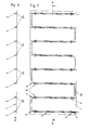
- Fig. 8 shows a floor plan of an inventive arrangement. It is particularly easy to see that here the tube 20 is formed meander-shaped and is held positively in all tube receptacles 2 of the support plate 1.
- Fig. 9 shows a sectional view along the section line AA of Fig. 8 , According to this embodiment 8 and 9 the arc of the meandering tube 20 are arranged within the outer contour of the carrier plate 1. For this purpose, the recesses 8 and the slots 9 in the carrier sheet 1 are introduced before the first forming process for producing the tube receptacles 2. This makes it possible to achieve a construction in which the meandering-shaped tube 20 remains within the outer contour of the carrier sheet 1.
- the recess 8 and the slot 9 can by known per se manufacturing processes, eg. B. punching etc. are introduced into the carrier sheet 1.
- Fig. 8 In this embodiment is in Fig. 8 Also clearly visible that the tube receptacles 2 are arranged in parallel and at the same distance from each other in their longitudinal extent. It is conceivable and possible to arrange the tube receptacles 2 deviating from a parallel orientation at any angle and at different distances from each other. In particular for support plates 1 as in Fig. 8 shown having a plurality of tube receptacles 2, the occurring thermally induced expansions and contractions with the aforementioned loop arrangement can be compensated locally become. As a result, high mechanical stresses are avoided, which would otherwise accumulate over the entire length of the support plate 1.
- the carrier sheet 1 does not necessarily have to be a rectangular sheet metal. Rather, other embodiments as circular sectors, polygons, etc. are conceivable.
Landscapes
- Engineering & Computer Science (AREA)
- Physics & Mathematics (AREA)
- Mechanical Engineering (AREA)
- Chemical & Material Sciences (AREA)
- General Engineering & Computer Science (AREA)
- Thermal Sciences (AREA)
- Sustainable Energy (AREA)
- Combustion & Propulsion (AREA)
- Sustainable Development (AREA)
- Life Sciences & Earth Sciences (AREA)
- Dispersion Chemistry (AREA)
- Geometry (AREA)
- Photovoltaic Devices (AREA)
- Vessels And Coating Films For Discharge Lamps (AREA)
- Heat-Exchange Devices With Radiators And Conduit Assemblies (AREA)
Applications Claiming Priority (1)
| Application Number | Priority Date | Filing Date | Title |
|---|---|---|---|
| ATA211/2013A AT513492B1 (de) | 2013-03-15 | 2013-03-15 | Trägerblech |
Publications (2)
| Publication Number | Publication Date |
|---|---|
| EP2778564A2 true EP2778564A2 (fr) | 2014-09-17 |
| EP2778564A3 EP2778564A3 (fr) | 2017-12-13 |
Family
ID=50179468
Family Applications (1)
| Application Number | Title | Priority Date | Filing Date |
|---|---|---|---|
| EP14000640.4A Withdrawn EP2778564A3 (fr) | 2013-03-15 | 2014-02-24 | Tôle support |
Country Status (2)
| Country | Link |
|---|---|
| EP (1) | EP2778564A3 (fr) |
| AT (1) | AT513492B1 (fr) |
Family Cites Families (7)
| Publication number | Priority date | Publication date | Assignee | Title |
|---|---|---|---|---|
| US2732615A (en) * | 1956-01-31 | sandberg | ||
| US2661191A (en) * | 1950-02-08 | 1953-12-01 | Houdaille Hershey Corp | Heat exchanger |
| FR1132683A (fr) * | 1955-10-05 | 1957-03-14 | Procédé pour la fixation d'un tube sur une plaque-support et appareils échangeursde chaleur ou analogues réalisables par ce procédé | |
| FR2383405A1 (fr) * | 1977-03-11 | 1978-10-06 | Renault Moteurs Dev | Echangeur de chaleur, notamment pour le captage de l'energie solaire et son procede de fabrication |
| WO2003001135A1 (fr) * | 2001-05-01 | 2003-01-03 | Romero Beltran Julian | Echangeur thermique de type plaque-tube |
| SK287288B6 (sk) * | 2006-03-24 | 2010-05-07 | Thermo/Solar Žiar, S. R. O. | Spôsob spájania absorpčnej platne s rúrkovým registrom termického slnečného kolektora |
| AT509380B1 (de) * | 2010-01-18 | 2012-04-15 | Bartelmuss Klaus Ing | Energiekollektor mit mindestens einem thermischen und einem fotovoltaischen kollektor |
-
2013
- 2013-03-15 AT ATA211/2013A patent/AT513492B1/de not_active IP Right Cessation
-
2014
- 2014-02-24 EP EP14000640.4A patent/EP2778564A3/fr not_active Withdrawn
Also Published As
| Publication number | Publication date |
|---|---|
| AT513492B1 (de) | 2014-05-15 |
| AT513492A4 (de) | 2014-05-15 |
| EP2778564A3 (fr) | 2017-12-13 |
Similar Documents
| Publication | Publication Date | Title |
|---|---|---|
| EP1811245B1 (fr) | Collecteur solaire modulaire | |
| EP2567423B1 (fr) | Dispositif de refroidissement d'une batterie | |
| EP2383533A2 (fr) | Agencement caloporteur, caloporteur et procédé de fabrication | |
| EP2065658A1 (fr) | Absorbeur solaire et son procédé de fabrication | |
| EP0041653B1 (fr) | Elément échangeur de chaleur | |
| EP0106262B1 (fr) | Echangeur thermique en particulier radiateur | |
| EP3134699B1 (fr) | Dispositif échangeur de chaleur et collecteur solaire | |
| EP1606565B1 (fr) | Absorbeur destine a un collecteur de chaleur d'une installation solaire et procede de production de cet absorbeur | |
| AT513492B1 (de) | Trägerblech | |
| DE102009026236A1 (de) | Verfahren zum stoffschlüssigen Verbinden von Fügepartnern | |
| DE102013111987A1 (de) | Verfahren zum Herstellen einer elektrischen Heizvorrichtung und Heizvorrichtung | |
| DE102011119403A1 (de) | Vorrichtung bestehend aus mindestens einem Wärmerohr und einem Sekundärkreislaufrohr | |
| CH702438A1 (de) | System und Verfahren für ein Hybridsystem zur Umwandlung von Solarstrahlung in elektrischen Strom und Wärme. | |
| EP2713407B1 (fr) | Ensemble de rééquipement d'un module photovoltaïque | |
| DE102013201582B4 (de) | Verfahren zur Herstellung einer Kühlvorrichtung für eine Batterieeinheit, Kühlvorrichtung für eine Batterieeinheit sowie Batterieeinheit | |
| DE102022123134B4 (de) | Photothermie-Modul | |
| DE202010015366U1 (de) | Solarthermischer Absorber | |
| AT512172B1 (de) | Absorber für solarstrahlung | |
| DE102014223178B4 (de) | Anpresskonzept für eine Kühleinrichtung eines Hochvoltspeichers | |
| AT412908B (de) | Absorber für einen sonnenkollektor | |
| DE202023001602U1 (de) | Lamellen-Wärmeübertrager | |
| DE102010053478B4 (de) | Wärmeübertrager und Herstellungsverfahren für Wärmeübertrager | |
| DE202017105805U1 (de) | Kollektor für Strahlungsenergie | |
| DE202009008081U1 (de) | Absorber | |
| DE102017222720A1 (de) | Kühlanordnung, Leistungselektronikvorrichtung mit einer Kühlanordnung, Verfahren zum Herstellen einer Kühlanordnung |
Legal Events
| Date | Code | Title | Description |
|---|---|---|---|
| PUAI | Public reference made under article 153(3) epc to a published international application that has entered the european phase |
Free format text: ORIGINAL CODE: 0009012 |
|
| 17P | Request for examination filed |
Effective date: 20140224 |
|
| AK | Designated contracting states |
Kind code of ref document: A2 Designated state(s): AL AT BE BG CH CY CZ DE DK EE ES FI FR GB GR HR HU IE IS IT LI LT LU LV MC MK MT NL NO PL PT RO RS SE SI SK SM TR |
|
| AX | Request for extension of the european patent |
Extension state: BA ME |
|
| PUAL | Search report despatched |
Free format text: ORIGINAL CODE: 0009013 |
|
| AK | Designated contracting states |
Kind code of ref document: A3 Designated state(s): AL AT BE BG CH CY CZ DE DK EE ES FI FR GB GR HR HU IE IS IT LI LT LU LV MC MK MT NL NO PL PT RO RS SE SI SK SM TR |
|
| AX | Request for extension of the european patent |
Extension state: BA ME |
|
| RIC1 | Information provided on ipc code assigned before grant |
Ipc: F28F 1/22 20060101ALI20171109BHEP Ipc: F28D 1/04 20060101ALI20171109BHEP Ipc: F24J 2/26 20060101AFI20171109BHEP |
|
| STAA | Information on the status of an ep patent application or granted ep patent |
Free format text: STATUS: THE APPLICATION IS DEEMED TO BE WITHDRAWN |
|
| 18D | Application deemed to be withdrawn |
Effective date: 20180614 |