EP2778672A1 - Appareil d'inspection de réseau à commande de phase ut - Google Patents
Appareil d'inspection de réseau à commande de phase ut Download PDFInfo
- Publication number
- EP2778672A1 EP2778672A1 EP14159097.6A EP14159097A EP2778672A1 EP 2778672 A1 EP2778672 A1 EP 2778672A1 EP 14159097 A EP14159097 A EP 14159097A EP 2778672 A1 EP2778672 A1 EP 2778672A1
- Authority
- EP
- European Patent Office
- Prior art keywords
- fixture
- inspection
- inner chamber
- inspection fixture
- ultrasonic signals
- Prior art date
- Legal status (The legal status is an assumption and is not a legal conclusion. Google has not performed a legal analysis and makes no representation as to the accuracy of the status listed.)
- Granted
Links
Images


Classifications
-
- G—PHYSICS
- G01—MEASURING; TESTING
- G01N—INVESTIGATING OR ANALYSING MATERIALS BY DETERMINING THEIR CHEMICAL OR PHYSICAL PROPERTIES
- G01N29/00—Investigating or analysing materials by the use of ultrasonic, sonic or infrasonic waves; Visualisation of the interior of objects by transmitting ultrasonic or sonic waves through the object
- G01N29/22—Details, e.g. general constructional or apparatus details
- G01N29/221—Arrangements for directing or focusing the acoustical waves
-
- G—PHYSICS
- G01—MEASURING; TESTING
- G01N—INVESTIGATING OR ANALYSING MATERIALS BY DETERMINING THEIR CHEMICAL OR PHYSICAL PROPERTIES
- G01N29/00—Investigating or analysing materials by the use of ultrasonic, sonic or infrasonic waves; Visualisation of the interior of objects by transmitting ultrasonic or sonic waves through the object
- G01N29/22—Details, e.g. general constructional or apparatus details
- G01N29/24—Probes
- G01N29/2456—Focusing probes
-
- G—PHYSICS
- G01—MEASURING; TESTING
- G01N—INVESTIGATING OR ANALYSING MATERIALS BY DETERMINING THEIR CHEMICAL OR PHYSICAL PROPERTIES
- G01N29/00—Investigating or analysing materials by the use of ultrasonic, sonic or infrasonic waves; Visualisation of the interior of objects by transmitting ultrasonic or sonic waves through the object
- G01N29/22—Details, e.g. general constructional or apparatus details
- G01N29/24—Probes
- G01N29/2487—Directing probes, e.g. angle probes
-
- G—PHYSICS
- G01—MEASURING; TESTING
- G01N—INVESTIGATING OR ANALYSING MATERIALS BY DETERMINING THEIR CHEMICAL OR PHYSICAL PROPERTIES
- G01N29/00—Investigating or analysing materials by the use of ultrasonic, sonic or infrasonic waves; Visualisation of the interior of objects by transmitting ultrasonic or sonic waves through the object
- G01N29/22—Details, e.g. general constructional or apparatus details
- G01N29/26—Arrangements for orientation or scanning by relative movement of the head and the sensor
- G01N29/262—Arrangements for orientation or scanning by relative movement of the head and the sensor by electronic orientation or focusing, e.g. with phased arrays
-
- G—PHYSICS
- G01—MEASURING; TESTING
- G01N—INVESTIGATING OR ANALYSING MATERIALS BY DETERMINING THEIR CHEMICAL OR PHYSICAL PROPERTIES
- G01N2291/00—Indexing codes associated with group G01N29/00
- G01N2291/02—Indexing codes associated with the analysed material
- G01N2291/023—Solids
- G01N2291/0231—Composite or layered materials
-
- G—PHYSICS
- G01—MEASURING; TESTING
- G01N—INVESTIGATING OR ANALYSING MATERIALS BY DETERMINING THEIR CHEMICAL OR PHYSICAL PROPERTIES
- G01N2291/00—Indexing codes associated with group G01N29/00
- G01N2291/04—Wave modes and trajectories
- G01N2291/045—External reflections, e.g. on reflectors
-
- G—PHYSICS
- G01—MEASURING; TESTING
- G01N—INVESTIGATING OR ANALYSING MATERIALS BY DETERMINING THEIR CHEMICAL OR PHYSICAL PROPERTIES
- G01N2291/00—Indexing codes associated with group G01N29/00
- G01N2291/10—Number of transducers
- G01N2291/106—Number of transducers one or more transducer arrays
Definitions
- Pi-bonded composite structures are used increasingly in military and commercial aircraft. Although pi-bonded composite laminates exhibit enhanced strength in comparison to conventional fastening methods, they are difficult to inspect for critical flaws. Furthermore, these structures tend to be large and geometrically complex, making conventional immersion ultrasonic and ultrasonic phased array inspections difficult or impossible. Finally, existing phased array hand-held fixtures do not allow complete inspection coverage of pi-bonds near joints, corners, and stiffeners.
- an inspection fixture in one embodiment, includes a body, an ultrasonic phase array, a mirror and a fluid supply connector.
- the fixture body includes an inner chamber.
- the body further has an opening to the inner chamber.
- the ultrasonic phase array generates ultrasonic signals.
- the mirror is received within the inner chamber.
- the mirror is positioned to reflect the ultrasonic signals out the opening to an inspection area of a body to be inspected and to reflect returned ultrasonic signals from the inspection area back to the ultrasonic phase array.
- the fluid supply connector is in fluid communication with the inner chamber.
- an inspection fixture in another embodiment, includes a fixture body, a lens, an ultrasonic phase array, a mirror and a liquid supply connector.
- the fixture body includes an inner chamber. The body further has an opening to the inner chamber.
- the lens defines a portion of the inner chamber.
- the ultrasonic phase array generates ultrasonic signals and is positioned to send the ultrasonic signals through the lens.
- the mirror is received within the inner chamber. The mirror is positioned at 45° in relation to the lens to reflect the ultrasonic signals from the lens out the opening to an inspection area of a body to be inspected and to reflect returned ultrasonic signals from the inspection area to the lens.
- the mirror being tapered.
- the liquid supply connector is in fluid communication with the inner chamber.
- a method of inspecting pi-bonds in a composite structure including: Generating ultrasonic signals with a ultrasonic phase array; directing the ultrasonic signals to a mirror in a chamber of a body that is filled with a column of liquid; reflecting the ultrasonic signals off of the mirror and through an opening in the chamber to an area to be inspected; and directing reflected ultrasonic signals off of the area being inspected back to the ultrasonic phase array.
- Embodiments of the present invention provide improved inspection capabilities for ultrasonic phased array inspection for pi-bonded composite structures, co-cured stiffened structures as well as other 90 degree joint bonded concepts (such as shear ties). Embodiments also provide inspection capabilities for acute and obtuse angled joints.
- a portable hand-held phased array scanning fixture (inspection fixture) is used to inspect pi-bonds.
- the fixture provides improved scanning coverage on pi-bond as well as improved resolution. This is done, in embodiments, by using an ultrasonic lens to focus a phased array beam across a width of a sensor, through a water column, onto a tapered mirror that reflects the beam into hard-to-reach joints, seams, corners, and tapers of the pi-bond.
- the fixture is compact and able to handle bonds exhibiting tight geometries, acute angles, obtuse angles, and hat stiffeners.
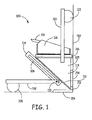
- the inspection fixture 100 includes a first member 102.
- a roller bearing 108 is coupled proximate a first end of the first member 102.
- a second end of the first member 102 is slidably coupled in an adjustment slot 106 of a second member 104 via connecting rod 110.
- the inspection fixture 100 includes an inner chamber 105 that holds a column of water.
- a water (or fluid) supply is fed and maintained by an inlet water hose on the back of the fixture 100.
- a mirror 112 defines a portion of the chamber. The mirror 112, in this embodiment, is coupled to a side of the second member 104.
- the mirror 112 in one embodiment ,is made from aluminum and in an embodiment is tapered.
- a focusing lens 116 further defines another portion of the inner chamber 114.
- the focusing lens is a RexoliteTM focusing lens.
- the lens 116 provides improved lateral flaw resolution across the width of the phased array
- Mounted to the lens 116 is an ultrasonic phase array sensor 118 that generates ultrasonic signals and receives reflected signals.
- the focusing lens 116 is positioned at 45° in relation to the mirror 112 so that ultrasonic waves generated by the ultrasonic phase array 118 is reflected off the mirror 112 to the area of the structure to be tested.
- the mirror is tapered to allow inspection up to the pi-bond joint and also into corners.
- the water column is used for acoustic transmission and coupling the ultrasonic signals.
- the ultrasonic signals that interact with the area to be inspected are reflected back off the mirror 112 back to the ultrasonic phase array 118.
- the reflected back ultrasonic signals are delivered via connection member 119 to a phased array receiver and processor (not shown in the Figure) for processing.
- a third member 120 that has a first end coupled proximate the sensor 118 and lens 116 and a second end that is coupled to a roller bearing 122.
- the roller bearings 108 and 122 allow the inspection fixture 100 to move across the part 150 to be inspected in a uniform manner.
- the flexibility of the inspection fixture 100 in this embodiment is illustrated. Because of the adjustable connection between the first member 102 and the second member 104, the inspection fixture can be adjusted to inspect areas structure 150 having corners that are less than 90° and more than 90°. Hence, in this embodiment, the adjustability between members 102 and 104 (that make up part of the body of the fixture 100) allow for joints of structures with many different configurations to be inspected with a single inspection fixture.
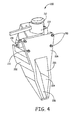
- FIG. 4 a front view of an inspection fixture 200 of another embodiment is illustrated.
- This embodiment includes a body 202 with an inner chamber 204. This view illustrates the opening 203 to the inner chamber 204.
- a mirror 206 is shown positioned within the inner chamber 204.
- a positioning plate 208 extends around the opening 203 to the inner chamber 204.
- adjustable spacers 210 extend out from the positioning plate 208 a select distance to help position the inspection fixture 200 in relation to the structure being inspected.
- This embodiment further includes a roller 212 that is in communication with a linear encoder 214.
- the linear encoder 214 is mounted to the body 202 of the fixture 200.
- the roller 212 rides on the laminates (structures to be inspected).
- the linear encoder 214 records positional information and is used to control timing of the phased array data acquisition signal.
- the linear encoder 214 is in communication with the processor (not shown in this Figure).
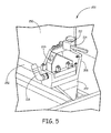
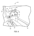
- FIGs 5 and 6 respective side perspective views of inspection fixture 200 are illustrated as positioned to inspect a pi-bond of a T shaped laminate structure.
- Figures 5 and 6 illustrate water connector 216.
- a water source, or fluid source, is coupled to the water connector 216 to provide a flow of water into the inner chamber 204 while the inspection fixture is in use.
- a supply/communication port 220 used at least in part to provide the ultrasonic energy to the fixture 200 and provide signals detected by the ultrasonic phased array to a processor system (not shown) via excitation/communication cable (such as cable 316 in Figure 7 ).
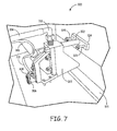
- Figure 7 further illustrates another embodiment of an inspection fixture 300 of an embodiment.
- Figure 7 further illustrates that the fixture 300 can be positioned to inspect a bottom joint portion 315.
- Inspection fixture 300 includes a body 302. Attached to the body 302 is a spacer assembly that includes a spacer rod 303 that extends from the body 302. A spacer bar 304 is attached to the end of the spacer rod 303. Adjustable spacers 320 and 322 are threadably engaged to the spacer bar 304. The adjustable spacers 320 and 322 are used to adjust fixture standoff and angle with respect to the laminate and pi bond. An optional "riding" cart can be attached to the fixture to facilitate scanning.
- Figure 7 further illustrates a roller 306 and linear encoder 308 that is in communication with a processor (not shown in this Figure) via communication channel 310. Also illustrated is an ultrasound communication channel 316 that provides a path for the ultrasonic energy and a communication path to the processor. Further, shown is a water supply 314 that is coupled to a water connector 312 to provide a water flow to an inner chamber.
- Figure 8 illustrates the inspection fixture 300 in a different position to inspect a different portion 317 of the pi-bond.
- Figure 9 illustrates a front perspective view of the inspection fixture 300.
- This view illustrates the inner chamber 330 and the mirror 332 positioned within the inner chamber 330.
- a skirt 334 is mounted around at least a portion of an opening 331 to the inner chamber 330.
- the skirt 334 is used to maintain water column pressure and stability as well as to conform to uneven and rough pi-bond and laminate geometries.
- the skirt is a porous membrane.
- spacing plate 340 that includes adjustable spacers 342 to position the fixture 300 at a desired location in relation to the structure to be inspected.
- Figure 10 illustrates how the inspection fixture can work to inspect a corner formed by structures 400, 402 and 404.
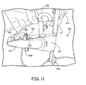
- FIG. 11 Another embodiment of an inspection fixture 500 is illustrated in Figure 11 .
- a porous membrane 504 covers up the opening to the chamber in the body 502.
- the porous membrane 504 is used to maintain the coupling of the acoustic transmission with the water column.
- This embodiment includes spacers 506a and 506b that are couple to the body 502. As shown, spacer 506a is coupled to the body via bracket 510 and fastener 508.
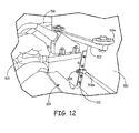
- the spacers 506a and 506b provide a spacing between the body 502 and the structure 550 being inspected as illustrated in Figure 12 . The spacing protects the integrity of the porous membrane 504 during inspection and maintains the porous membrane 504 in a consistent configuration during inspection across the structure.
- the inspection fixture 500 of this embodiment also includes an arm 512 extending from a positioning plate 510. Attached to opposite ends of the arm 512 are bearings 514a and 514b, which in this embodiment, are used as spacers as well as wheels to assist in the moving of the inspection fixture across the structure 550.
- Figure 12 also shows an excitation/communication cable 516 which is coupled to the fixture's ultrasonic phase array. Also illustrated is the fixture's water supply conduit 518.
- an inspection flow diagram 600 of one embodiment is illustrated.
- the process starts by positioning the fixture in relation to the structure to be inspected (602).
- the fixture standoff and angle, with respect to the bond being inspected, is then adjusted (604).
- a liquid flow is then started, which in one embodiment is a flow of water (606).
- Ultrasonic signals are then generated (608).
- the linear movement of a body of the inspection fixture is monitored (610) and recorded (612).
- This information is provided to processor 700 which uses the information to control the timing of phased array data acquisition signals (622).
- the process directs the ultrasonic signals to a mirror in a chamber of the body (616).
- the ultrasonic signals are reflected off the mirror and through an opening in the chamber to a joint area to be inspected (618).
- Reflected ultrasonic signals off of the area being inspected are directed back to a sensor of the ultrasonic phase array by the mirror and the sensed information is passed on to the processor 700.
- the processor 700 processes the signals from the sensor to determine the integrity of the joint (614).
- the results of the determination are displayed to a user (624). The results can then be used to determine if the part passes inspection.
Landscapes
- Physics & Mathematics (AREA)
- Health & Medical Sciences (AREA)
- Life Sciences & Earth Sciences (AREA)
- Chemical & Material Sciences (AREA)
- Analytical Chemistry (AREA)
- Biochemistry (AREA)
- General Health & Medical Sciences (AREA)
- General Physics & Mathematics (AREA)
- Immunology (AREA)
- Pathology (AREA)
- Acoustics & Sound (AREA)
- Investigating Or Analyzing Materials By The Use Of Ultrasonic Waves (AREA)
Applications Claiming Priority (1)
| Application Number | Priority Date | Filing Date | Title |
|---|---|---|---|
| US13/829,988 US9372173B2 (en) | 2013-03-14 | 2013-03-14 | Ultrasonic testing phased array inspection fixture and related methods |
Publications (2)
| Publication Number | Publication Date |
|---|---|
| EP2778672A1 true EP2778672A1 (fr) | 2014-09-17 |
| EP2778672B1 EP2778672B1 (fr) | 2019-11-27 |
Family
ID=50241225
Family Applications (1)
| Application Number | Title | Priority Date | Filing Date |
|---|---|---|---|
| EP14159097.6A Active EP2778672B1 (fr) | 2013-03-14 | 2014-03-12 | Appareil d'inspection de réseau à commande de phase ut |
Country Status (2)
| Country | Link |
|---|---|
| US (1) | US9372173B2 (fr) |
| EP (1) | EP2778672B1 (fr) |
Cited By (2)
| Publication number | Priority date | Publication date | Assignee | Title |
|---|---|---|---|---|
| CN107014900A (zh) * | 2017-03-31 | 2017-08-04 | 中国商用飞机有限责任公司北京民用飞机技术研究中心 | 一种用于复合材料r区的超声相控阵检测装置 |
| US10302600B2 (en) | 2016-01-19 | 2019-05-28 | Northrop Grumman Innovation Systems, Inc. | Inspection devices and related systems and methods |
Families Citing this family (4)
| Publication number | Priority date | Publication date | Assignee | Title |
|---|---|---|---|---|
| US9372173B2 (en) * | 2013-03-14 | 2016-06-21 | Orbital Atk, Inc. | Ultrasonic testing phased array inspection fixture and related methods |
| US9746447B2 (en) | 2014-10-30 | 2017-08-29 | The Boeing Company | Apparatuses, systems, and methods for inspecting a component |
| US9664652B2 (en) * | 2014-10-30 | 2017-05-30 | The Boeing Company | Non-destructive ultrasonic inspection apparatus, systems, and methods |
| US9625424B2 (en) * | 2015-02-13 | 2017-04-18 | Olympus Scientific Solutions Americas Inc. | System and a method of automatically generating a phased array ultrasound scan plan for non-destructive inspection |
Citations (3)
| Publication number | Priority date | Publication date | Assignee | Title |
|---|---|---|---|---|
| US3550438A (en) * | 1967-10-06 | 1970-12-29 | Siderurgie Fse Inst Rech | Ultrasonic testing system for hot objects |
| US4848159A (en) * | 1987-05-22 | 1989-07-18 | The Boeing Company | Ultrasonic inspection probe for laminated structures |
| JPH049149A (ja) * | 1990-04-27 | 1992-01-13 | Aloka Co Ltd | 三次元データ取込み用超音波探触子 |
Family Cites Families (40)
| Publication number | Priority date | Publication date | Assignee | Title |
|---|---|---|---|---|
| US3802533A (en) * | 1968-05-20 | 1974-04-09 | Holotron Corp | Improvements in and relating to ultrasonic lenses |
| US3895685A (en) * | 1971-04-19 | 1975-07-22 | Combustion Eng | Method and apparatus for ultrasonic inspection of weldments |
| FR2141540B1 (fr) * | 1971-06-15 | 1974-03-08 | Thomson Csf | |
| US3780572A (en) * | 1972-09-18 | 1973-12-25 | Gen Electric | Ultrasonic inspection apparatus |
| US3924453A (en) * | 1973-05-04 | 1975-12-09 | United States Steel Corp | Ultrasonic testing of tubing employing a spiral wave generator |
| US4200858A (en) * | 1976-12-28 | 1980-04-29 | Canon Kabushiki Kaisha | Acoustic wave scanning apparatus |
| FR2443072A1 (fr) * | 1978-04-20 | 1980-06-27 | Commissariat Energie Atomique | Optique pour exploration d'une piece par un faisceau |
| US4508122A (en) * | 1982-11-22 | 1985-04-02 | Ultramed, Inc. | Ultrasonic scanning apparatus and techniques |
| JPH0654307B2 (ja) * | 1986-10-08 | 1994-07-20 | 動力炉・核燃料開発事業団 | 液体一固体系内の超音波可視化方法及び装置 |
| US5419196A (en) * | 1993-03-19 | 1995-05-30 | Pandrol Jackson Technologies, Inc. | Ultrasonic side-looker for rail head flaw detection |
| US5282472A (en) * | 1993-05-11 | 1994-02-01 | Companion John A | System and process for the detection, evaluation and treatment of prostate and urinary problems |
| US5421200A (en) * | 1993-08-26 | 1995-06-06 | General Electric Company | Ultrasonic fixture assembly for holding multiple ultrasonic transducers |
| JPH07184898A (ja) * | 1993-12-28 | 1995-07-25 | Olympus Optical Co Ltd | 超音波プローブ |
| US5698787A (en) * | 1995-04-12 | 1997-12-16 | Mcdonnell Douglas Corporation | Portable laser/ultrasonic method for nondestructive inspection of complex structures |
| US6830189B2 (en) * | 1995-12-18 | 2004-12-14 | Metrologic Instruments, Inc. | Method of and system for producing digital images of objects with subtantially reduced speckle-noise patterns by illuminating said objects with spatially and/or temporally coherent-reduced planar laser illumination |
| AUPO884297A0 (en) * | 1997-08-27 | 1997-09-18 | Orme, Gregory Michael | Imaging devices |
| US6069698A (en) * | 1997-08-28 | 2000-05-30 | Olympus Optical Co., Ltd. | Optical imaging apparatus which radiates a low coherence light beam onto a test object, receives optical information from light scattered by the object, and constructs therefrom a cross-sectional image of the object |
| TW490559B (en) * | 1999-07-30 | 2002-06-11 | Hitachi Construction Machinery | Ultrasonic inspection apparatus and ultrasonic detector |
| CA2324572A1 (fr) * | 2000-10-26 | 2002-04-26 | Gerry M. Kane | Transducteur de vibration numerique |
| US20030222977A1 (en) * | 2002-06-03 | 2003-12-04 | Kazutora Yoshino | Intelligent system and 3D virtual object generator |
| US7263888B2 (en) * | 2003-10-16 | 2007-09-04 | General Electric Company | Two dimensional phased arrays for volumetric ultrasonic inspection and methods of use |
| US7293461B1 (en) * | 2003-10-22 | 2007-11-13 | Richard Girndt | Ultrasonic tubulars inspection device |
| US7484413B2 (en) * | 2003-12-12 | 2009-02-03 | The Boeing Company | Remote radius inspection tool for composite joints |
| US7496456B2 (en) * | 2004-04-26 | 2009-02-24 | Kabushiki Kaisha Toshiba | 3D ultrasonographic device |
| WO2006020341A2 (fr) * | 2004-07-23 | 2006-02-23 | Massachusetts Institute Of Technology | Caracterisation de materiaux avec des formes d'onde acoustiques optiquement formees |
| US7337673B2 (en) * | 2005-07-11 | 2008-03-04 | The Boeing Company | Ultrasonic array probe apparatus, system, and method for traveling over holes and off edges of a structure |
| US7275442B2 (en) * | 2005-04-21 | 2007-10-02 | General Electric Company | Method for ultrasonic inspection of generator field teeth |
| US20060272418A1 (en) * | 2005-06-03 | 2006-12-07 | Brown University | Opto-acoustic methods and apparatus for perfoming high resolution acoustic imaging and other sample probing and modification operations |
| EP1742049B1 (fr) * | 2005-07-07 | 2009-12-09 | Kabushiki Kaisha Toshiba | Appareil de maintenance basé sur un laser |
| US7751113B2 (en) * | 2006-01-23 | 2010-07-06 | Texas Instruments Incorporated | Micromirrors having mirror plates with tapered edges |
| JP4096014B2 (ja) * | 2006-08-08 | 2008-06-04 | 日立Geニュークリア・エナジー株式会社 | 原子炉圧力容器の超音波検査方法及び装置 |
| JP4839333B2 (ja) * | 2008-03-19 | 2011-12-21 | 日立Geニュークリア・エナジー株式会社 | 超音波検査方法および超音波検査装置 |
| WO2010045421A2 (fr) * | 2008-10-15 | 2010-04-22 | University Of Rochester | Imagerie photoacoustique à l'aide d'une lentille acoustique polyvalente |
| FR2940450B1 (fr) * | 2008-12-22 | 2011-02-18 | Centre Nat Rech Scient | Dispositif et procede pour etudier une zone d'etude par onde acoustique |
| US8087298B1 (en) * | 2009-03-10 | 2012-01-03 | Sandia Corporation | Ultrasonic probe deployment device for increased wave transmission and rapid area scan inspections |
| CN102946809A (zh) * | 2010-02-01 | 2013-02-27 | 松下电器产业株式会社 | 超声波探测器以及使用该超声波探测器的超声波检査装置 |
| CA3013169C (fr) * | 2010-03-15 | 2020-10-27 | The Board Of Trustees Of The Leland Stanford Junior University | Capteur acoustique compatible avec une fibre optique |
| US9110000B2 (en) * | 2012-02-17 | 2015-08-18 | General Electric Company | Method and system for determining the position of an ultrasonic wedge and a probe |
| US8943892B2 (en) * | 2012-05-11 | 2015-02-03 | The Boeing Company | Automated inspection of spar web in hollow monolithic structure |
| US9372173B2 (en) * | 2013-03-14 | 2016-06-21 | Orbital Atk, Inc. | Ultrasonic testing phased array inspection fixture and related methods |
-
2013
- 2013-03-14 US US13/829,988 patent/US9372173B2/en active Active
-
2014
- 2014-03-12 EP EP14159097.6A patent/EP2778672B1/fr active Active
Patent Citations (3)
| Publication number | Priority date | Publication date | Assignee | Title |
|---|---|---|---|---|
| US3550438A (en) * | 1967-10-06 | 1970-12-29 | Siderurgie Fse Inst Rech | Ultrasonic testing system for hot objects |
| US4848159A (en) * | 1987-05-22 | 1989-07-18 | The Boeing Company | Ultrasonic inspection probe for laminated structures |
| JPH049149A (ja) * | 1990-04-27 | 1992-01-13 | Aloka Co Ltd | 三次元データ取込み用超音波探触子 |
Cited By (4)
| Publication number | Priority date | Publication date | Assignee | Title |
|---|---|---|---|---|
| US10302600B2 (en) | 2016-01-19 | 2019-05-28 | Northrop Grumman Innovation Systems, Inc. | Inspection devices and related systems and methods |
| US10962506B2 (en) | 2016-01-19 | 2021-03-30 | Northrop Grumman Systems Corporation | Inspection devices and related systems and methods |
| CN107014900A (zh) * | 2017-03-31 | 2017-08-04 | 中国商用飞机有限责任公司北京民用飞机技术研究中心 | 一种用于复合材料r区的超声相控阵检测装置 |
| CN107014900B (zh) * | 2017-03-31 | 2019-07-26 | 中国商用飞机有限责任公司北京民用飞机技术研究中心 | 一种用于复合材料r区的超声相控阵检测装置 |
Also Published As
| Publication number | Publication date |
|---|---|
| US20140260630A1 (en) | 2014-09-18 |
| EP2778672B1 (fr) | 2019-11-27 |
| US9372173B2 (en) | 2016-06-21 |
Similar Documents
| Publication | Publication Date | Title |
|---|---|---|
| EP2778672B1 (fr) | Appareil d'inspection de réseau à commande de phase ut | |
| US8371173B1 (en) | Ultrasonic probe deployment device for increased wave transmission and rapid area scan inspections | |
| US10261053B2 (en) | Ultrasound inspection | |
| EP2691736B1 (fr) | Outil de profilage pour déterminer l'épaisseur d'une matière, destiné à des sites d'inspection ayant une topographie complexe | |
| US8365602B2 (en) | Weld seam tracking system using phased array ultrasonic devices | |
| US11420692B2 (en) | Surface wave detection of surface defects | |
| KR101736641B1 (ko) | 균열 측정 장치 및 방법 | |
| US20180231502A1 (en) | Automated ultrasonic inspection of adhesively-bonded joints and inspection method therefor | |
| CN107490624A (zh) | 超薄金属焊缝检测系统及其检测方法 | |
| TWI623747B (zh) | 層積體之剝離檢查方法及剝離檢查裝置 | |
| EP3259587A1 (fr) | Procédé de contrôle d'un cordon de soudure à l'aide d'un réseau ultrasonore piloté en phase | |
| WO2019109661A1 (fr) | Système de détection automatique ultrasonore en réseau phasé pour cordon de soudure par friction-malaxage de réservoir de fusée | |
| JP6328760B2 (ja) | 材料検査装置 | |
| Bulavinov et al. | Ultrasonic sampling phased array testing as a replacement for x-ray testing of weld joints in ship construction | |
| EP3919897B1 (fr) | Inspection de zone morte avec test ultrasonique utilisant une intégration de signal | |
| US20240302324A1 (en) | Adaptable apparatus for non-destructive inspection | |
| RU148954U1 (ru) | Сканер для ультразвукового контроля протяженных сварных швов | |
| Lines et al. | Rapid, Low-Cost, Full-Wave Form Mapping and Analysis with Ultrasonic Arrays | |
| Bulavinov et al. | ray Testing of Weld Joints in Ship Construction | |
| Horn et al. | Computer controlled ultrasonic inspection of pulsed magnetic welded fuel pins | |
| Shan et al. | Ultrasonic phased array inspection imaging technology for NDT of offshore platform structures | |
| Smith et al. | Linear-array systems for aerospace NDE |
Legal Events
| Date | Code | Title | Description |
|---|---|---|---|
| 17P | Request for examination filed |
Effective date: 20140312 |
|
| AK | Designated contracting states |
Kind code of ref document: A1 Designated state(s): AL AT BE BG CH CY CZ DE DK EE ES FI FR GB GR HR HU IE IS IT LI LT LU LV MC MK MT NL NO PL PT RO RS SE SI SK SM TR |
|
| AX | Request for extension of the european patent |
Extension state: BA ME |
|
| PUAI | Public reference made under article 153(3) epc to a published international application that has entered the european phase |
Free format text: ORIGINAL CODE: 0009012 |
|
| R17P | Request for examination filed (corrected) |
Effective date: 20150317 |
|
| RBV | Designated contracting states (corrected) |
Designated state(s): AL AT BE BG CH CY CZ DE DK EE ES FI FR GB GR HR HU IE IS IT LI LT LU LV MC MK MT NL NO PL PT RO RS SE SI SK SM TR |
|
| RAP1 | Party data changed (applicant data changed or rights of an application transferred) |
Owner name: ORBITAL ATK, INC. |
|
| GRAP | Despatch of communication of intention to grant a patent |
Free format text: ORIGINAL CODE: EPIDOSNIGR1 |
|
| STAA | Information on the status of an ep patent application or granted ep patent |
Free format text: STATUS: GRANT OF PATENT IS INTENDED |
|
| INTG | Intention to grant announced |
Effective date: 20190103 |
|
| RAP1 | Party data changed (applicant data changed or rights of an application transferred) |
Owner name: NORTHROP GRUMMAN INNOVATION SYSTEMS, INC. |
|
| GRAJ | Information related to disapproval of communication of intention to grant by the applicant or resumption of examination proceedings by the epo deleted |
Free format text: ORIGINAL CODE: EPIDOSDIGR1 |
|
| STAA | Information on the status of an ep patent application or granted ep patent |
Free format text: STATUS: REQUEST FOR EXAMINATION WAS MADE |
|
| GRAP | Despatch of communication of intention to grant a patent |
Free format text: ORIGINAL CODE: EPIDOSNIGR1 |
|
| STAA | Information on the status of an ep patent application or granted ep patent |
Free format text: STATUS: GRANT OF PATENT IS INTENDED |
|
| INTC | Intention to grant announced (deleted) | ||
| INTG | Intention to grant announced |
Effective date: 20190605 |
|
| GRAS | Grant fee paid |
Free format text: ORIGINAL CODE: EPIDOSNIGR3 |
|
| GRAA | (expected) grant |
Free format text: ORIGINAL CODE: 0009210 |
|
| STAA | Information on the status of an ep patent application or granted ep patent |
Free format text: STATUS: THE PATENT HAS BEEN GRANTED |
|
| AK | Designated contracting states |
Kind code of ref document: B1 Designated state(s): AL AT BE BG CH CY CZ DE DK EE ES FI FR GB GR HR HU IE IS IT LI LT LU LV MC MK MT NL NO PL PT RO RS SE SI SK SM TR |
|
| REG | Reference to a national code |
Ref country code: GB Ref legal event code: FG4D |
|
| REG | Reference to a national code |
Ref country code: CH Ref legal event code: EP |
|
| REG | Reference to a national code |
Ref country code: AT Ref legal event code: REF Ref document number: 1207275 Country of ref document: AT Kind code of ref document: T Effective date: 20191215 |
|
| REG | Reference to a national code |
Ref country code: DE Ref legal event code: R096 Ref document number: 602014057376 Country of ref document: DE |
|
| REG | Reference to a national code |
Ref country code: IE Ref legal event code: FG4D |
|
| REG | Reference to a national code |
Ref country code: NL Ref legal event code: MP Effective date: 20191127 |
|
| REG | Reference to a national code |
Ref country code: LT Ref legal event code: MG4D |
|
| PG25 | Lapsed in a contracting state [announced via postgrant information from national office to epo] |
Ref country code: ES Free format text: LAPSE BECAUSE OF FAILURE TO SUBMIT A TRANSLATION OF THE DESCRIPTION OR TO PAY THE FEE WITHIN THE PRESCRIBED TIME-LIMIT Effective date: 20191127 Ref country code: NL Free format text: LAPSE BECAUSE OF FAILURE TO SUBMIT A TRANSLATION OF THE DESCRIPTION OR TO PAY THE FEE WITHIN THE PRESCRIBED TIME-LIMIT Effective date: 20191127 Ref country code: NO Free format text: LAPSE BECAUSE OF FAILURE TO SUBMIT A TRANSLATION OF THE DESCRIPTION OR TO PAY THE FEE WITHIN THE PRESCRIBED TIME-LIMIT Effective date: 20200227 Ref country code: GR Free format text: LAPSE BECAUSE OF FAILURE TO SUBMIT A TRANSLATION OF THE DESCRIPTION OR TO PAY THE FEE WITHIN THE PRESCRIBED TIME-LIMIT Effective date: 20200228 Ref country code: BG Free format text: LAPSE BECAUSE OF FAILURE TO SUBMIT A TRANSLATION OF THE DESCRIPTION OR TO PAY THE FEE WITHIN THE PRESCRIBED TIME-LIMIT Effective date: 20200227 Ref country code: FI Free format text: LAPSE BECAUSE OF FAILURE TO SUBMIT A TRANSLATION OF THE DESCRIPTION OR TO PAY THE FEE WITHIN THE PRESCRIBED TIME-LIMIT Effective date: 20191127 Ref country code: LT Free format text: LAPSE BECAUSE OF FAILURE TO SUBMIT A TRANSLATION OF THE DESCRIPTION OR TO PAY THE FEE WITHIN THE PRESCRIBED TIME-LIMIT Effective date: 20191127 Ref country code: LV Free format text: LAPSE BECAUSE OF FAILURE TO SUBMIT A TRANSLATION OF THE DESCRIPTION OR TO PAY THE FEE WITHIN THE PRESCRIBED TIME-LIMIT Effective date: 20191127 Ref country code: SE Free format text: LAPSE BECAUSE OF FAILURE TO SUBMIT A TRANSLATION OF THE DESCRIPTION OR TO PAY THE FEE WITHIN THE PRESCRIBED TIME-LIMIT Effective date: 20191127 |
|
| PG25 | Lapsed in a contracting state [announced via postgrant information from national office to epo] |
Ref country code: HR Free format text: LAPSE BECAUSE OF FAILURE TO SUBMIT A TRANSLATION OF THE DESCRIPTION OR TO PAY THE FEE WITHIN THE PRESCRIBED TIME-LIMIT Effective date: 20191127 Ref country code: RS Free format text: LAPSE BECAUSE OF FAILURE TO SUBMIT A TRANSLATION OF THE DESCRIPTION OR TO PAY THE FEE WITHIN THE PRESCRIBED TIME-LIMIT Effective date: 20191127 Ref country code: IS Free format text: LAPSE BECAUSE OF FAILURE TO SUBMIT A TRANSLATION OF THE DESCRIPTION OR TO PAY THE FEE WITHIN THE PRESCRIBED TIME-LIMIT Effective date: 20200327 |
|
| PG25 | Lapsed in a contracting state [announced via postgrant information from national office to epo] |
Ref country code: AL Free format text: LAPSE BECAUSE OF FAILURE TO SUBMIT A TRANSLATION OF THE DESCRIPTION OR TO PAY THE FEE WITHIN THE PRESCRIBED TIME-LIMIT Effective date: 20191127 |
|
| PG25 | Lapsed in a contracting state [announced via postgrant information from national office to epo] |
Ref country code: RO Free format text: LAPSE BECAUSE OF FAILURE TO SUBMIT A TRANSLATION OF THE DESCRIPTION OR TO PAY THE FEE WITHIN THE PRESCRIBED TIME-LIMIT Effective date: 20191127 Ref country code: CZ Free format text: LAPSE BECAUSE OF FAILURE TO SUBMIT A TRANSLATION OF THE DESCRIPTION OR TO PAY THE FEE WITHIN THE PRESCRIBED TIME-LIMIT Effective date: 20191127 Ref country code: DK Free format text: LAPSE BECAUSE OF FAILURE TO SUBMIT A TRANSLATION OF THE DESCRIPTION OR TO PAY THE FEE WITHIN THE PRESCRIBED TIME-LIMIT Effective date: 20191127 Ref country code: EE Free format text: LAPSE BECAUSE OF FAILURE TO SUBMIT A TRANSLATION OF THE DESCRIPTION OR TO PAY THE FEE WITHIN THE PRESCRIBED TIME-LIMIT Effective date: 20191127 Ref country code: PT Free format text: LAPSE BECAUSE OF FAILURE TO SUBMIT A TRANSLATION OF THE DESCRIPTION OR TO PAY THE FEE WITHIN THE PRESCRIBED TIME-LIMIT Effective date: 20200419 |
|
| REG | Reference to a national code |
Ref country code: DE Ref legal event code: R097 Ref document number: 602014057376 Country of ref document: DE |
|
| PG25 | Lapsed in a contracting state [announced via postgrant information from national office to epo] |
Ref country code: SK Free format text: LAPSE BECAUSE OF FAILURE TO SUBMIT A TRANSLATION OF THE DESCRIPTION OR TO PAY THE FEE WITHIN THE PRESCRIBED TIME-LIMIT Effective date: 20191127 Ref country code: SM Free format text: LAPSE BECAUSE OF FAILURE TO SUBMIT A TRANSLATION OF THE DESCRIPTION OR TO PAY THE FEE WITHIN THE PRESCRIBED TIME-LIMIT Effective date: 20191127 |
|
| REG | Reference to a national code |
Ref country code: AT Ref legal event code: MK05 Ref document number: 1207275 Country of ref document: AT Kind code of ref document: T Effective date: 20191127 |
|
| REG | Reference to a national code |
Ref country code: DE Ref legal event code: R119 Ref document number: 602014057376 Country of ref document: DE |
|
| PLBE | No opposition filed within time limit |
Free format text: ORIGINAL CODE: 0009261 |
|
| STAA | Information on the status of an ep patent application or granted ep patent |
Free format text: STATUS: NO OPPOSITION FILED WITHIN TIME LIMIT |
|
| PG25 | Lapsed in a contracting state [announced via postgrant information from national office to epo] |
Ref country code: MC Free format text: LAPSE BECAUSE OF FAILURE TO SUBMIT A TRANSLATION OF THE DESCRIPTION OR TO PAY THE FEE WITHIN THE PRESCRIBED TIME-LIMIT Effective date: 20191127 |
|
| REG | Reference to a national code |
Ref country code: CH Ref legal event code: PL |
|
| 26N | No opposition filed |
Effective date: 20200828 |
|
| PG25 | Lapsed in a contracting state [announced via postgrant information from national office to epo] |
Ref country code: SI Free format text: LAPSE BECAUSE OF FAILURE TO SUBMIT A TRANSLATION OF THE DESCRIPTION OR TO PAY THE FEE WITHIN THE PRESCRIBED TIME-LIMIT Effective date: 20191127 Ref country code: AT Free format text: LAPSE BECAUSE OF FAILURE TO SUBMIT A TRANSLATION OF THE DESCRIPTION OR TO PAY THE FEE WITHIN THE PRESCRIBED TIME-LIMIT Effective date: 20191127 Ref country code: PL Free format text: LAPSE BECAUSE OF FAILURE TO SUBMIT A TRANSLATION OF THE DESCRIPTION OR TO PAY THE FEE WITHIN THE PRESCRIBED TIME-LIMIT Effective date: 20191127 |
|
| REG | Reference to a national code |
Ref country code: BE Ref legal event code: MM Effective date: 20200331 |
|
| PG25 | Lapsed in a contracting state [announced via postgrant information from national office to epo] |
Ref country code: LU Free format text: LAPSE BECAUSE OF NON-PAYMENT OF DUE FEES Effective date: 20200312 |
|
| PG25 | Lapsed in a contracting state [announced via postgrant information from national office to epo] |
Ref country code: DE Free format text: LAPSE BECAUSE OF NON-PAYMENT OF DUE FEES Effective date: 20201001 Ref country code: LI Free format text: LAPSE BECAUSE OF NON-PAYMENT OF DUE FEES Effective date: 20200331 Ref country code: CH Free format text: LAPSE BECAUSE OF NON-PAYMENT OF DUE FEES Effective date: 20200331 Ref country code: IT Free format text: LAPSE BECAUSE OF FAILURE TO SUBMIT A TRANSLATION OF THE DESCRIPTION OR TO PAY THE FEE WITHIN THE PRESCRIBED TIME-LIMIT Effective date: 20191127 Ref country code: IE Free format text: LAPSE BECAUSE OF NON-PAYMENT OF DUE FEES Effective date: 20200312 |
|
| PG25 | Lapsed in a contracting state [announced via postgrant information from national office to epo] |
Ref country code: BE Free format text: LAPSE BECAUSE OF NON-PAYMENT OF DUE FEES Effective date: 20200331 |
|
| GBPC | Gb: european patent ceased through non-payment of renewal fee |
Effective date: 20200312 |
|
| PG25 | Lapsed in a contracting state [announced via postgrant information from national office to epo] |
Ref country code: GB Free format text: LAPSE BECAUSE OF NON-PAYMENT OF DUE FEES Effective date: 20200312 |
|
| PG25 | Lapsed in a contracting state [announced via postgrant information from national office to epo] |
Ref country code: TR Free format text: LAPSE BECAUSE OF FAILURE TO SUBMIT A TRANSLATION OF THE DESCRIPTION OR TO PAY THE FEE WITHIN THE PRESCRIBED TIME-LIMIT Effective date: 20191127 Ref country code: MT Free format text: LAPSE BECAUSE OF FAILURE TO SUBMIT A TRANSLATION OF THE DESCRIPTION OR TO PAY THE FEE WITHIN THE PRESCRIBED TIME-LIMIT Effective date: 20191127 Ref country code: CY Free format text: LAPSE BECAUSE OF FAILURE TO SUBMIT A TRANSLATION OF THE DESCRIPTION OR TO PAY THE FEE WITHIN THE PRESCRIBED TIME-LIMIT Effective date: 20191127 |
|
| PG25 | Lapsed in a contracting state [announced via postgrant information from national office to epo] |
Ref country code: MK Free format text: LAPSE BECAUSE OF FAILURE TO SUBMIT A TRANSLATION OF THE DESCRIPTION OR TO PAY THE FEE WITHIN THE PRESCRIBED TIME-LIMIT Effective date: 20191127 |
|
| P01 | Opt-out of the competence of the unified patent court (upc) registered |
Effective date: 20230607 |
|
| PGFP | Annual fee paid to national office [announced via postgrant information from national office to epo] |
Ref country code: FR Payment date: 20260320 Year of fee payment: 13 |