EP2778710A2 - Positionnement intérieur avec mesure de retard de propagation de signal comprimé de fréquence radio - Google Patents
Positionnement intérieur avec mesure de retard de propagation de signal comprimé de fréquence radio Download PDFInfo
- Publication number
- EP2778710A2 EP2778710A2 EP14158036.5A EP14158036A EP2778710A2 EP 2778710 A2 EP2778710 A2 EP 2778710A2 EP 14158036 A EP14158036 A EP 14158036A EP 2778710 A2 EP2778710 A2 EP 2778710A2
- Authority
- EP
- European Patent Office
- Prior art keywords
- chirp
- spread spectrum
- range
- determining
- signal
- Prior art date
- Legal status (The legal status is an assumption and is not a legal conclusion. Google has not performed a legal analysis and makes no representation as to the accuracy of the status listed.)
- Withdrawn
Links
- 238000005259 measurement Methods 0.000 title description 16
- 238000001228 spectrum Methods 0.000 claims abstract description 51
- 238000000034 method Methods 0.000 claims abstract description 20
- 230000010363 phase shift Effects 0.000 claims abstract description 14
- 230000001934 delay Effects 0.000 claims description 5
- 230000003111 delayed effect Effects 0.000 claims description 3
- 230000005540 biological transmission Effects 0.000 description 15
- 238000010586 diagram Methods 0.000 description 5
- 238000013459 approach Methods 0.000 description 4
- 230000000694 effects Effects 0.000 description 4
- 230000004044 response Effects 0.000 description 4
- 230000007480 spreading Effects 0.000 description 3
- 230000015556 catabolic process Effects 0.000 description 2
- 239000002131 composite material Substances 0.000 description 2
- 238000006731 degradation reaction Methods 0.000 description 2
- 238000005516 engineering process Methods 0.000 description 2
- 230000002452 interceptive effect Effects 0.000 description 2
- 238000013507 mapping Methods 0.000 description 2
- 238000005070 sampling Methods 0.000 description 2
- 230000018199 S phase Effects 0.000 description 1
- 230000006978 adaptation Effects 0.000 description 1
- 238000009435 building construction Methods 0.000 description 1
- 239000004035 construction material Substances 0.000 description 1
- 238000001802 infusion Methods 0.000 description 1
- 230000003993 interaction Effects 0.000 description 1
- 238000012544 monitoring process Methods 0.000 description 1
- 238000012546 transfer Methods 0.000 description 1
- 230000001131 transforming effect Effects 0.000 description 1
Images



Classifications
-
- G—PHYSICS
- G01—MEASURING; TESTING
- G01S—RADIO DIRECTION-FINDING; RADIO NAVIGATION; DETERMINING DISTANCE OR VELOCITY BY USE OF RADIO WAVES; LOCATING OR PRESENCE-DETECTING BY USE OF THE REFLECTION OR RERADIATION OF RADIO WAVES; ANALOGOUS ARRANGEMENTS USING OTHER WAVES
- G01S5/00—Position-fixing by co-ordinating two or more direction or position line determinations; Position-fixing by co-ordinating two or more distance determinations
- G01S5/02—Position-fixing by co-ordinating two or more direction or position line determinations; Position-fixing by co-ordinating two or more distance determinations using radio waves
- G01S5/06—Position of source determined by co-ordinating a plurality of position lines defined by path-difference measurements
-
- G—PHYSICS
- G01—MEASURING; TESTING
- G01S—RADIO DIRECTION-FINDING; RADIO NAVIGATION; DETERMINING DISTANCE OR VELOCITY BY USE OF RADIO WAVES; LOCATING OR PRESENCE-DETECTING BY USE OF THE REFLECTION OR RERADIATION OF RADIO WAVES; ANALOGOUS ARRANGEMENTS USING OTHER WAVES
- G01S13/00—Systems using the reflection or reradiation of radio waves, e.g. radar systems; Analogous systems using reflection or reradiation of waves whose nature or wavelength is irrelevant or unspecified
- G01S13/87—Combinations of radar systems, e.g. primary radar and secondary radar
- G01S13/876—Combination of several spaced transponders or reflectors of known location for determining the position of a receiver
-
- G—PHYSICS
- G01—MEASURING; TESTING
- G01S—RADIO DIRECTION-FINDING; RADIO NAVIGATION; DETERMINING DISTANCE OR VELOCITY BY USE OF RADIO WAVES; LOCATING OR PRESENCE-DETECTING BY USE OF THE REFLECTION OR RERADIATION OF RADIO WAVES; ANALOGOUS ARRANGEMENTS USING OTHER WAVES
- G01S5/00—Position-fixing by co-ordinating two or more direction or position line determinations; Position-fixing by co-ordinating two or more distance determinations
- G01S5/02—Position-fixing by co-ordinating two or more direction or position line determinations; Position-fixing by co-ordinating two or more distance determinations using radio waves
- G01S5/0205—Details
- G01S5/0218—Multipath in signal reception
-
- G—PHYSICS
- G01—MEASURING; TESTING
- G01S—RADIO DIRECTION-FINDING; RADIO NAVIGATION; DETERMINING DISTANCE OR VELOCITY BY USE OF RADIO WAVES; LOCATING OR PRESENCE-DETECTING BY USE OF THE REFLECTION OR RERADIATION OF RADIO WAVES; ANALOGOUS ARRANGEMENTS USING OTHER WAVES
- G01S5/00—Position-fixing by co-ordinating two or more direction or position line determinations; Position-fixing by co-ordinating two or more distance determinations
- G01S5/02—Position-fixing by co-ordinating two or more direction or position line determinations; Position-fixing by co-ordinating two or more distance determinations using radio waves
- G01S5/14—Determining absolute distances from a plurality of spaced points of known location
-
- G—PHYSICS
- G01—MEASURING; TESTING
- G01S—RADIO DIRECTION-FINDING; RADIO NAVIGATION; DETERMINING DISTANCE OR VELOCITY BY USE OF RADIO WAVES; LOCATING OR PRESENCE-DETECTING BY USE OF THE REFLECTION OR RERADIATION OF RADIO WAVES; ANALOGOUS ARRANGEMENTS USING OTHER WAVES
- G01S13/00—Systems using the reflection or reradiation of radio waves, e.g. radar systems; Analogous systems using reflection or reradiation of waves whose nature or wavelength is irrelevant or unspecified
- G01S13/87—Combinations of radar systems, e.g. primary radar and secondary radar
- G01S13/878—Combination of several spaced transmitters or receivers of known location for determining the position of a transponder or a reflector
-
- G—PHYSICS
- G01—MEASURING; TESTING
- G01S—RADIO DIRECTION-FINDING; RADIO NAVIGATION; DETERMINING DISTANCE OR VELOCITY BY USE OF RADIO WAVES; LOCATING OR PRESENCE-DETECTING BY USE OF THE REFLECTION OR RERADIATION OF RADIO WAVES; ANALOGOUS ARRANGEMENTS USING OTHER WAVES
- G01S5/00—Position-fixing by co-ordinating two or more direction or position line determinations; Position-fixing by co-ordinating two or more distance determinations
- G01S5/02—Position-fixing by co-ordinating two or more direction or position line determinations; Position-fixing by co-ordinating two or more distance determinations using radio waves
- G01S5/0273—Position-fixing by co-ordinating two or more direction or position line determinations; Position-fixing by co-ordinating two or more distance determinations using radio waves using multipath or indirect path propagation signals in position determination
Definitions
- GPS Global Position System
- Various technologies have attempted to combine GPS data (taken when a device was outside) with other information, such as Cell triangulation, Wifi and accelerometer data to try and estimate indoor position with greater accuracy.
- Another approach to determining indoor positioning is to use previously installed nodes to record signal strength- using the proximity to these sensors to establish approximate locations.
- radios that are capable of determining distance, it is possible to provide positioning of an object or person inside of a building. This can be used to track emergency personnel such as firemen, equipment such as medical infusion pumps in hospitals, or military robotic vehicles exploring indoor spaces to determine safety.
- a simple signal such as a sine wave for ranging in such an environment can lead to uncertainty as to the timing or phase of the sine wave signal being received; superimposition of a multipath or reflected sinusoid onto a prompt ray sinusoid can lead to difficulty in distinguishing the prompt ray from the multipath ray.
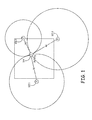
- Fig. 1 illustrates a locator system 100 that can be used to locate an object or a person inside a structure such as a building.
- system 100 of Fig. 1 three radio frequency (RF) nodes 102.1-102.3 are placed external to a building.
- each of the nodes 102 has the ability to determine range based on radio transmissions. Between them, they triangulate the position of object 104 using chirp spread spectrum signals in the manner detailed below.
- Nodes 102 and 104 cooperate to establish the distance between each node 102 and node 104.
- each node 102 determines range to node 104 via a round-trip transmission of the chirp-based signal from node 102 to node 104, or from node 104 to node 102. In other example embodiments, node 104 determines range to each node 102 via a round-trip transmission of the chirp-based signal from node 104 to node 102.
- nodes 102 transmit a wider bandwidth spread spectrum signal instead of the discrete tones to reduce the effects of multipath, Since delayed shifts of a spread spectrum signal are uncorrelated with one another, the effect of multipath upon the phase measurements will be greatly reduced.
- each node 102 is a reference node used to triangulate object 104 (the position node).
- Accurate ranging measurement using a chirp sequence spread spectrum signal means that nodes 102 can be placed in a position outside the structure where an object is to be located and can still locate the position node very accurately. If we know the position of each of the reference nodes accurately, we can determine an absolute location of the object as a function of the position of the reference nodes.
- each reference node' positions can be established via GPS, via differential GPS or from known coordinates based on, for instance, a previous survey, known map coordinates or known indoor building coordinates.
- each reference node includes a global positioning system sensor, wherein the reference nodes determine their location based on data from the global positioning system sensor.
- each reference node includes an interface for receiving location data.
- location data is loaded by a user based on a previous survey, known map coordinates or known indoor building coordinates.
- similar data is downloaded to each reference node via a network from, for instance, a local or cloud-based server.
- reference nodes 102 operate with position node 104 to establish its position.
- each reference node 102 determines range to the position node 104.
- the range information for each reference node 102 is then sent with the node's known coordinates to the position node 104 as a data packet and the position node determines its position based on the range information and the known coordinates of each reference node 102.
- position node 104 transmits a chirp spread spectrum signal to each reference node 102 and determines range to each node 102 as a function of the return signal from each reference node 102.
- the reference ranging information accumulated for each reference node 102 at the position node 104 is sent to one of the reference nodes (the aggregator reference node) and, in one embodiment, is used to locate the position node in reference to the aggregator reference node 102.
- reference nodes 102 operate with position node 104 to establish the position of position node 102 for an outside person or device.
- An example locator system 200 is shown in Fig. 2 .
- three radio frequency (RF) nodes 102.1-102.3 are placed external to a building.
- each of the nodes 102 has the ability to determine range based on radio transmissions. Between them, they triangulate the position of object 104 using chirp spread spectrum signals in the manner detailed below.
- One or more of the nodes 102 and 104 are connected via a network to a server such as cloud server 202.
- Nodes 102 and 104 cooperate to establish the distance between each node 102 and node 104. To establish this distance, in some example embodiments, each node 102 determines range to node 104 via a round-trip transmission of the chirp-based signal from node 102 to node 104, or from node 104 to node 102.
- position node 104 transmits a chirp spread spectrum signal to each reference node 102 and determines range to each node 102 as a function of the return signal from each reference node 102.
- the reference ranging information accumulated for each reference node 102 at the position node 104 is sent to server 202 either directly from positioning node 104 or through one of the reference nodes 102.
- one or more reference nodes determine ranging information and transfer the information to server 202.
- raw range data from position node 104 is sent to the cloud either from position node 104, or the range information is sent to each reference node 102 and they individually send the information on to the cloud.
- one of the RN nodes acts as a range data aggregator and sends the accumulated data to server 202 at appropriate intervals.
- raw range data is sent to server 202 the cloud either by each individual node or through one of the nodes acting as a gateway.
- the location of position node 104 can then be computed via the raw data by the gateway prior to sending the data to the cloud, by cloud server 202 itself, or by an application running on a PC 204 or a smart phone 206 that retrieves the raw data from the cloud and computes the position.
- a chirp spread spectrum ranging transmit signal that can be used in systems 100 and 200 will be discussed next.
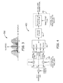
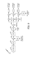
- FIG. 4 shows an example multi-frequency chirp transmitter 400 which can be used in node 102 to provide a chirp-based ranging signal.
- Transmitter 400 produces a transmit signal with a spectrum 300 such as is shown in Fig. 3 .
- three un-modulated, length 512 chirp sequences are transmitted as the ranging signal.
- the chirps are centered at frequencies of -Fr, 0, and +Fr.
- the first chirp sweeps from -2Fr to 0, the second sweeps from -Fr to +Fr, and the third sweeps from 0 to +2Fr as shown at 300.
- the chirp sequences in this example are transmitted simultaneously but they may also be transmitted individually at separate times.
- a length 512 complex chirp sequence is generated and then multiplied by a real-valued length 512 windowing function.
- the fine timing of the transmission may be set by either introducing phase offsets on the chirp waveforms (at 408) or by adjusting the time delay using an interpolation/decimation filter (at 406). These are shown as optional functions on the block diagram.
- the windowed chirp sequence is replicated three times and fed to a length 1024 inverse FFT at 402 to convert the signal to the time domain.
- a chirp sequence in the frequency domain is equivalent to the complex conjugate of the chirp sequence in the time domain. Therefore, transforming a chirp sequence in the frequency domain to the time domain simply creates a chirp sequence that sweeps in the opposite direction.
- the composite signal is then filtered with an up-sampling low pass filter at 404 and optionally delayed with a fine timing interpolation filter at 406.
- the arrival of the prompt ray is estimated with a high degree of accuracy.
- a spreading code with a 20MHz bandwidth provides a resolution of only 50 nanoseconds; this is roughly fifty feet in terms of distance.
- three half-bandwidth chirps are transmitted offset in frequency by 0, +Fr, and -Fr, where Fr is equal to one-fourth the transmission bandwidth, BW.
- the three chirps are sent with the same phase.
- the three phases will be identical. If the receive signal is offset in time, the three phases will shift due to the frequency offset of each chirp signal. Using a combination of the chirp offset and the chirp phases, the propagation delay of the RF signal can be very accurately estimated.
- Chirp spreading reduces the influence ofmultipath on the measurement; note, however, that multipath with delays less than a chirp period from the prompt ray may still interfere with the measurement.
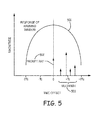
- Figure 5 shows an example of multipath or reflected rays less than a chirp period from the prompt ray interfering with prompt ray reception, consistent with an example embodiment of the invention.
- the magnitude response of the hamming window is shown at 501, centered around the prompt ray 502. Any multipath 503 within this window will combine with the prompt ray and potentially interfere with the measurement.
- Figure 6 illustrates shifting the hamming window despreading offset to minimize multipath interference with the prompt ray, consistent with an example embodiment of the invention.
- the de-spread offset is advanced as much as is practical while still maintaining an accurate phase measurement.
- the offset in a more detailed example is advanced until the de-spread energy drops to a pre-determined threshold level. At this offset, the phase measurement takes place. This results in the hamming window capturing the prompt ray 602, while greatly attenuating or excluding the multipath signals 603.
- the phase measurement is important for providing an accurate measurement.
- the relative phases of the frequency chirps reflect the de-spread timing offset with respect to the received ray. This is a direct consequence of the two chirp signals having a non-zero center frequency.
- the chirp centered at -BW/4 will experience a phase shift of - ⁇ k/2 radians, where k is the time difference between the ray and the de-spread offset in units of Ts.
- the chirp centered at +BW/4 will experience a phase shift of + ⁇ k/2 radians.
- the third chirp signal located at 0 Hz is used as a phase reference and does not experience a phase shift when the de-spread offset changes.
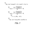
- Figure 7 shows calculation of chirp phases, consistent with an example embodiment of the invention.
- the reference phase, ⁇ 0 is calculated at 701
- C° is the complex despread value for the zero frequency centered or DC chirp
- C - is the complex despread value for the negative frequency centered chirp
- C + is the complex despread value for the positive frequency centered chirp.
- the fine timing offset, k can then be calculated as shown at 704.
- a third chirp symbol is added at DC, and a reference phase is calculated from the DC chirp as shown at 705.
- the raw timing measurement is then the coarse timing offset corresponding to the point of the delay measurement minus this fine timing value.
- the internal path delays of both radios is also subtracted.
- the delay is adjusted based on the estimate of the relative oscillator inaccuracies between the two radios.
- the effect of multipath on the de-spread prompt ray at the receiver is minimized by selecting a timing offset near the estimated location of the prompt ray.
- the location is based upon the estimated channel impulse response.
- One method for determining the approximate prompt ray offset is to select the earliest arriving offset whose energy is above a threshold. The threshold can then be calculated relative to the maximum energy offset or relative to the composite signal energy.
- a block of data is buffered and transformed into the frequency domain.
- the data from the FFT is separated into the proper frequency band for each chirp, and then the data is de-spread in the frequency domain.
- frequency domain de-spreading is almost identical to time domain de-spreading because a chirp signal in the frequency domain is simply the complex conjugate of the signal in the time domain.
- the signal is de-spread by correlating the data with a chirp sequence.
- any multipath following the prompt ray is desirable to attenuate any multipath following the prompt ray in order to obtain a reliable phase measurement of the prompt ray signal. This is accomplished by advancing the time offset as illustrated previously in Figure 6 . However, each time the time offset is adjusted, a computation-intensive FFT is performed. In order to avoid this complexity, some embodiments of the invention employ a method in which the FFT window is effectively moved but the timing offset remains stationary. This is accomplished by multiplying each band of FFT output data by a near-DC complex sinusoid. The frequency of the complex sinusoid is adjusted to position the window such that the prompt ray's phase can be measured with little influence from any nearby multipath. The frequency is adjusted until the de-spread energy of the chirp symbols are within a given range. At this point, the phase of the de-spread chirp symbols is measured. The phases reflect the fine timing offset of the prompt ray relative to the coarse data buffer timing.
- the station receiving the range request signal responds with a range reply transmission at a known delay following the request.
- the timing of the transmission is precise, so that the round trip delay estimate is accurate.
- the transmit timing can be conveyed in different manners, including:
- the third option is used, sending the fine timing offset information in a data portion of the range reply frame.
- FIG. 8 shows a block diagram of a ranging receiver, consistent with an example embodiment of the invention.
- a transceiver 801 down converts the RF signal to a 0 Hz IF signal (baseband signal).
- An ADC 802 converts the analog baseband signal to a digital signal. Any frequency offset error is corrected by multiplying the baseband signal with a complex sinusoid generated by a numerically-controlled oscillator (NCO) at 803.
- NCO numerically-controlled oscillator
- the data is then low-pass filtered at 804 and buffered at 805 to create a block of data (length of 1024 in this example).
- the block of data feeds a 1024 point FFT at 806, which converts the time domain data into the frequency domain.
- the FFT output is separated into three bands: the upper band centered at +Fc which uses FFT output bins 0 through 511, the middle band centered at DC (0 Hz) which uses FFT output bins 0 through 255 and 768 through 1023, and the lower band centered a -Fc which uses FFT output bins 512 through 1023.
- the data for each of the three frequency bands is multiplied by a windowing function and the chirp sequence.
- the data is then multiplied a third time by a complex sinusoid fed by an NCO.
- the 512 data samples for each frequency band are accumulated to provide the de-spread chirp values.
- the frequency of the NCO is adjusted based upon the energy of the de-spread chirp symbols.
- the phases of the three de-spread chirp values are measured.
- the phase values provide the fine timing offset of the prompt ray relative to the coarse offset. Note that the chirp phase and NCO phase are combined to eliminate one of the complex multiply operations in a further example.
- FIG. 9 is a block diagram of an alternate implementation of a ranging receiver, consistent with an example embodiment of the invention.
- the signal is despread in the time domain eliminating the need for a fast fourier transform.
- the block of data at the output of buffer 905 is multiplied by the windowing function by multiplier 906. This data is then multiplied by the complex conjugate of the expected data sequences.
- the data sequence chirp0 is the chirp signal generated at the sampling rate of the received block of data.
- the data sequence, chirp+ is the chirp0 sequence multiplied by a positive frequency offset of +Fc; likewise, chirp- is the chirp0 sequence multiplied by a negative frequency offset of -Fc.
- the three signals are multiplied by a complex sinusoid and then accumulated to produce the despread symbols.
- timing offset of the buffered data may not align precisely with the received symbols resulting in a misalignment of the windowing function. However, when using long chirp sequences this degradation is fairly insignificant. In either implementation it may also be desirable to compensate for any non-linear phase or magnitude variations in the response of the radio's signal path. This may be accomplished by multiplying the received block of data by a complex data sequence derived from measuring the channel response of the radio.
- These examples illustrate how distance between two radio frequency devices can be estimated by receiving a plurality of spread spectrum chirp signals frequency offset from one another, and evaluating the received plurality of spread spectrum chirp signals for relative phase shifts between the plurality of spread spectrum chirp signals.
- a fine propagation time is derived using the phase shifts between the spread spectrum chirp signals.
- a frequency domain despreading window is shifted to reduce the influence of time-delayed near multipath signals in receiving the plurality of spread spectrum chirp signals.
- the reference nodes can be either inside or outside of the building, and with only three nodes it could be possible to get better accuracy than current methods. Also, while only three reference nodes are required for accurate positioning, a fourth reference node located at a different height is all that would be required to determine the floor of a multi-story building. With the reference nodes 102 external to the building, their position can be accurately determined without the need for any pre-mapping of internal structures. With the nodes indoors, minimal mapping may be required, or the units could be located near windows and get a reference position via GPS. Additional reference nodes do not have to be added to improve accuracy as with other methods. Additional nodes only need to be added if the indoor structure is sufficiently large as to limit the radio range to a minimum of three devices.
- Position data can be accumulated on the cloud and provided for computation of positional data and for consumption by various devices
Landscapes
- Engineering & Computer Science (AREA)
- Radar, Positioning & Navigation (AREA)
- Remote Sensing (AREA)
- Physics & Mathematics (AREA)
- General Physics & Mathematics (AREA)
- Computer Networks & Wireless Communication (AREA)
- Position Fixing By Use Of Radio Waves (AREA)
- Radar Systems Or Details Thereof (AREA)
Applications Claiming Priority (1)
| Application Number | Priority Date | Filing Date | Title |
|---|---|---|---|
| US13/830,291 US9766321B2 (en) | 2013-03-14 | 2013-03-14 | Indoor positioning with radio frequency chirp signal propagation delay measurement |
Publications (2)
| Publication Number | Publication Date |
|---|---|
| EP2778710A2 true EP2778710A2 (fr) | 2014-09-17 |
| EP2778710A3 EP2778710A3 (fr) | 2014-10-08 |
Family
ID=50241140
Family Applications (1)
| Application Number | Title | Priority Date | Filing Date |
|---|---|---|---|
| EP14158036.5A Withdrawn EP2778710A3 (fr) | 2013-03-14 | 2014-03-06 | Positionnement intérieur avec mesure de retard de propagation de signal comprimé de fréquence radio |
Country Status (2)
| Country | Link |
|---|---|
| US (1) | US9766321B2 (fr) |
| EP (1) | EP2778710A3 (fr) |
Cited By (2)
| Publication number | Priority date | Publication date | Assignee | Title |
|---|---|---|---|---|
| CN105158732A (zh) * | 2015-06-24 | 2015-12-16 | 浙江工业大学 | 一种无线传感器网络协助的移动机器人自定位方法 |
| EP4462149A1 (fr) | 2023-05-12 | 2024-11-13 | Lambda: 4 Entwicklungen GmbH | Détermination de position par télémétrie spectrale |
Families Citing this family (12)
| Publication number | Priority date | Publication date | Assignee | Title |
|---|---|---|---|---|
| US20150201309A1 (en) * | 2008-06-12 | 2015-07-16 | Board Of Trustees Of Northern Illinois University | System and method for wireless positioning and location determination |
| US9338034B2 (en) * | 2013-10-09 | 2016-05-10 | Qualcomm Incorporated | Ternary sequences with power of two exponent dimensionalities suitable for channel estimation |
| EP3071987A1 (fr) * | 2013-11-21 | 2016-09-28 | Tracewave GmbH | Système de localisation css |
| US9800288B2 (en) * | 2015-03-03 | 2017-10-24 | Semtech Corporation | Communication device and method in the cellular band |
| CN105357754B (zh) * | 2015-11-02 | 2018-08-10 | 中国电子科技集团公司第二十八研究所 | 一种基于无线网络的移动节点组合定位方法 |
| EP3273607B1 (fr) * | 2016-07-20 | 2023-01-18 | Semtech Corporation | Procédé et système de synchronisation et de localisation d'un signal radio |
| CN109118794A (zh) * | 2017-06-22 | 2019-01-01 | 中兴通讯股份有限公司 | 车辆定位方法、装置和终端设备 |
| US10989803B1 (en) | 2017-08-21 | 2021-04-27 | Massachusetts Institute Of Technology | Security protocol for motion tracking systems |
| US10278155B1 (en) * | 2018-01-19 | 2019-04-30 | Cisco Technology, Inc. | Monitor radio assisted fine timing measurement for location applications |
| WO2019190519A1 (fr) * | 2018-03-29 | 2019-10-03 | Intel IP Corporation | Appareil, système et procédé de mesure de distance |
| CN116600378B (zh) * | 2023-05-09 | 2025-12-09 | 深圳市国电科技通信有限公司 | 基于LoRa调制的频偏估计方法、装置及介质、频偏估计设备 |
| US20250038838A1 (en) * | 2023-07-28 | 2025-01-30 | Zhejiang University | Frequency-shift Symmetric Chirp Spread Spectrum Modulation and Demodulation Method for Interstellar Communication Links |
Family Cites Families (19)
| Publication number | Priority date | Publication date | Assignee | Title |
|---|---|---|---|---|
| US4532603A (en) | 1983-03-09 | 1985-07-30 | The United States Of America As Represented By The Secretary Of The Army | Chirp transform correlator |
| US6396866B1 (en) | 1998-05-01 | 2002-05-28 | Trw Inc. | Symmetric chirp communications acquisition method and apparatus |
| US6493405B1 (en) | 1999-03-02 | 2002-12-10 | Harris Corporation | Correlator having enhanced memory for reference and input data |
| DE19961777A1 (de) | 1999-12-21 | 2001-07-12 | Rudolf Bannasch | Verfahren und Vorrichtungen zur Informationsübertragung |
| US7177343B1 (en) | 2000-05-17 | 2007-02-13 | Zenith Electronics Corporation | Compound chirp and synchronizer for using same |
| GB0121491D0 (en) * | 2001-09-05 | 2001-10-24 | Thales Res Ltd | Position fixing system |
| US7068704B1 (en) * | 2001-09-26 | 2006-06-27 | Itt Manufacturing Enterpprises, Inc. | Embedded chirp signal for position determination in cellular communication systems |
| CA2480846A1 (fr) | 2002-04-10 | 2003-11-06 | Nanotron Technologies Gmbh | Dispositif emetteur-recepteur |
| CA2515513A1 (fr) | 2003-02-25 | 2004-09-10 | Yokohama Tlo Company, Ltd. | Procede pour produire des formes d'impulsion |
| US6943405B2 (en) | 2003-07-01 | 2005-09-13 | International Business Machines Corporation | Integrated circuit having pairs of parallel complementary FinFETs |
| US7702002B2 (en) | 2004-01-28 | 2010-04-20 | Qualcomm Incorporated | Rapid acquisition methods and apparatus for GPS signals |
| WO2006058006A2 (fr) | 2004-11-22 | 2006-06-01 | Baker Hughes Incorporated | Identification de reponse de frequence de canal a l'aide de signaux chirp et de frequences en palier |
| US8483703B2 (en) * | 2005-11-14 | 2013-07-09 | Motorola Solutions, Inc. | Method and apparatus for locating a transceiver |
| US9088348B2 (en) * | 2007-06-18 | 2015-07-21 | Digi International Inc. | System and method for obtaining frequency and time synchronization in a wideband communication system |
| US9088349B2 (en) | 2007-06-18 | 2015-07-21 | Digi International Inc. | System and method for transmitting and detecting spread spectrum signals |
| DE202008005467U1 (de) * | 2008-04-18 | 2009-08-27 | Rittal Gmbh & Co. Kg | Positionsüberwachungseinrichtung für Personen |
| KR101040254B1 (ko) | 2008-07-11 | 2011-06-09 | 광주과학기술원 | 단방향 측정 기법을 이용한 위치 추정 방법 및 시스템 |
| US8976060B2 (en) | 2011-05-23 | 2015-03-10 | Digi International Inc. | RF chirp signal propagation delay measurement |
| US8861568B2 (en) * | 2011-11-22 | 2014-10-14 | Novatel Inc. | Chirp receiver utilizing phase processed chirp signals |
-
2013
- 2013-03-14 US US13/830,291 patent/US9766321B2/en active Active
-
2014
- 2014-03-06 EP EP14158036.5A patent/EP2778710A3/fr not_active Withdrawn
Non-Patent Citations (1)
| Title |
|---|
| None |
Cited By (2)
| Publication number | Priority date | Publication date | Assignee | Title |
|---|---|---|---|---|
| CN105158732A (zh) * | 2015-06-24 | 2015-12-16 | 浙江工业大学 | 一种无线传感器网络协助的移动机器人自定位方法 |
| EP4462149A1 (fr) | 2023-05-12 | 2024-11-13 | Lambda: 4 Entwicklungen GmbH | Détermination de position par télémétrie spectrale |
Also Published As
| Publication number | Publication date |
|---|---|
| US9766321B2 (en) | 2017-09-19 |
| EP2778710A3 (fr) | 2014-10-08 |
| US20140266914A1 (en) | 2014-09-18 |
Similar Documents
| Publication | Publication Date | Title |
|---|---|---|
| US9766321B2 (en) | Indoor positioning with radio frequency chirp signal propagation delay measurement | |
| US8866672B2 (en) | Cooperative systems and methods for TDOA-based emitter location | |
| US8976060B2 (en) | RF chirp signal propagation delay measurement | |
| US6801782B2 (en) | Method and apparatus for determining the position of a mobile communication device | |
| US8199047B2 (en) | High-precision radio frequency ranging system | |
| US7561048B2 (en) | Methods and system for reduced attenuation in tracking objects using RF technology | |
| EP3114496B1 (fr) | Système de positionnement en intérieur utilisant la différence en temps de vol entre des signaux rf et acoustiques | |
| US12413385B2 (en) | Methods for time synchronization and localization in a mesh network | |
| KR102145095B1 (ko) | Rf를 사용하여 위치 파악하기 위한 부분적으로 동기화된 다변측량 또는 삼변측량 방법 및 시스템 | |
| EP2679064B1 (fr) | Procédé pour estimer la distance d'un récepteur à un émetteur radio, procédés relatifs pour calculer la position d'un terminal mobile, terminal mobile et dispositif de localisation | |
| CN102165332B (zh) | 空间飞行器位置估计系统和方法 | |
| US7304609B2 (en) | Hybrid wireless ranging system and associated methods | |
| US11668785B2 (en) | Method for locating a connected object by phase differences of arrival in an LPWA network | |
| EP2642312B1 (fr) | Système à matériel réduit pour localisation TDOA d'émetteurs de fréquence radio | |
| Roehr et al. | Novel secondary radar for precise distance and velocity measurement in multipath environments | |
| Galler et al. | Analysis and practical comparison of Wireless LAN and Ultra-Wideband technologies for advanced localization | |
| WO2020141415A1 (fr) | Système de positionnement amélioré basé sur une émission et une réception distribuées de signaux wi-fi | |
| Dasala et al. | Synchronized Uplink Time of Arrival Localization: A Measurement-driven Evaluation | |
| Renner et al. | Characterization of dense multipath effects for non-coherent GMSK wireless channels in indoor environments | |
| Zhou | Indoor localization with ultra wideband radio | |
| Capizzio | Distributed spectrum sensing for the localization of two-way radio transmitters |
Legal Events
| Date | Code | Title | Description |
|---|---|---|---|
| PUAL | Search report despatched |
Free format text: ORIGINAL CODE: 0009013 |
|
| 17P | Request for examination filed |
Effective date: 20140306 |
|
| AK | Designated contracting states |
Kind code of ref document: A2 Designated state(s): AL AT BE BG CH CY CZ DE DK EE ES FI FR GB GR HR HU IE IS IT LI LT LU LV MC MK MT NL NO PL PT RO RS SE SI SK SM TR |
|
| AX | Request for extension of the european patent |
Extension state: BA ME |
|
| PUAI | Public reference made under article 153(3) epc to a published international application that has entered the european phase |
Free format text: ORIGINAL CODE: 0009012 |
|
| AK | Designated contracting states |
Kind code of ref document: A3 Designated state(s): AL AT BE BG CH CY CZ DE DK EE ES FI FR GB GR HR HU IE IS IT LI LT LU LV MC MK MT NL NO PL PT RO RS SE SI SK SM TR |
|
| AX | Request for extension of the european patent |
Extension state: BA ME |
|
| RIC1 | Information provided on ipc code assigned before grant |
Ipc: G01S 5/14 20060101AFI20140902BHEP Ipc: G01S 13/74 20060101ALI20140902BHEP |
|
| R17P | Request for examination filed (corrected) |
Effective date: 20150408 |
|
| RBV | Designated contracting states (corrected) |
Designated state(s): AL AT BE BG CH CY CZ DE DK EE ES FI FR GB GR HR HU IE IS IT LI LT LU LV MC MK MT NL NO PL PT RO RS SE SI SK SM TR |
|
| 17Q | First examination report despatched |
Effective date: 20160714 |
|
| STAA | Information on the status of an ep patent application or granted ep patent |
Free format text: STATUS: THE APPLICATION HAS BEEN WITHDRAWN |
|
| 18W | Application withdrawn |
Effective date: 20200324 |