EP2778809A2 - Simulationsverfahren und Systeme für ein Flugzeug - Google Patents
Simulationsverfahren und Systeme für ein Flugzeug Download PDFInfo
- Publication number
- EP2778809A2 EP2778809A2 EP14158151.2A EP14158151A EP2778809A2 EP 2778809 A2 EP2778809 A2 EP 2778809A2 EP 14158151 A EP14158151 A EP 14158151A EP 2778809 A2 EP2778809 A2 EP 2778809A2
- Authority
- EP
- European Patent Office
- Prior art keywords
- simulation
- parameter
- omc
- test
- aircraft
- Prior art date
- Legal status (The legal status is an assumption and is not a legal conclusion. Google has not performed a legal analysis and makes no representation as to the accuracy of the status listed.)
- Withdrawn
Links
Images



Classifications
-
- G—PHYSICS
- G06—COMPUTING OR CALCULATING; COUNTING
- G06F—ELECTRIC DIGITAL DATA PROCESSING
- G06F30/00—Computer-aided design [CAD]
- G06F30/10—Geometric CAD
- G06F30/15—Vehicle, aircraft or watercraft design
-
- B—PERFORMING OPERATIONS; TRANSPORTING
- B64—AIRCRAFT; AVIATION; COSMONAUTICS
- B64F—GROUND OR AIRCRAFT-CARRIER-DECK INSTALLATIONS SPECIALLY ADAPTED FOR USE IN CONNECTION WITH AIRCRAFT; DESIGNING, MANUFACTURING, ASSEMBLING, CLEANING, MAINTAINING OR REPAIRING AIRCRAFT, NOT OTHERWISE PROVIDED FOR; HANDLING, TRANSPORTING, TESTING OR INSPECTING AIRCRAFT COMPONENTS, NOT OTHERWISE PROVIDED FOR
- B64F5/00—Designing, manufacturing, assembling, cleaning, maintaining or repairing aircraft, not otherwise provided for; Handling, transporting, testing or inspecting aircraft components, not otherwise provided for
- B64F5/60—Testing or inspecting aircraft components or systems
-
- G—PHYSICS
- G05—CONTROLLING; REGULATING
- G05B—CONTROL OR REGULATING SYSTEMS IN GENERAL; FUNCTIONAL ELEMENTS OF SUCH SYSTEMS; MONITORING OR TESTING ARRANGEMENTS FOR SUCH SYSTEMS OR ELEMENTS
- G05B17/00—Systems involving the use of models or simulators of said systems
- G05B17/02—Systems involving the use of models or simulators of said systems electric
-
- G—PHYSICS
- G05—CONTROLLING; REGULATING
- G05B—CONTROL OR REGULATING SYSTEMS IN GENERAL; FUNCTIONAL ELEMENTS OF SUCH SYSTEMS; MONITORING OR TESTING ARRANGEMENTS FOR SUCH SYSTEMS OR ELEMENTS
- G05B23/00—Testing or monitoring of control systems or parts thereof
- G05B23/02—Electric testing or monitoring
- G05B23/0205—Electric testing or monitoring by means of a monitoring system capable of detecting and responding to faults
- G05B23/0208—Electric testing or monitoring by means of a monitoring system capable of detecting and responding to faults characterized by the configuration of the monitoring system
- G05B23/0216—Human interface functionality, e.g. monitoring system providing help to the user in the selection of tests or in its configuration
Definitions
- the present disclosure generally relates to methods and systems for driving simulations in an aircraft, and more particularly to methods and systems for driving simulations from a low criticality maintenance system in an aircraft.
- Confirmation of the proper operation of an aircraft or an aircraft system is typically required during the production of the aircraft system and/or in association with a maintenance procedure being performed on the aircraft system. This confirmation, often times, requires simulating or reproducing a particular environment or flight scenario of the aircraft. In order to reproduce the particular environment or flight scenario, a series of artificial maneuvers are created by manipulating one or more flight parameters over a range of values. This typically requires the time consuming process of setting breakers, disconnecting sensors, and connecting multiple pieces of automated test equipment with pre-programmed simulation scripts to reproduce the conditions.
- a method for performing a simulation on an aircraft. The method includes: receiving, at an onboard maintenance computer (OMC), a simulation script that includes one or more steps for adjusting at least one parameter of the aircraft; processing, by the OMC, the simulation script to determine simulation data; and sending the simulation data from the OMC to one or more signal producer member systems of the aircraft to adjust the at least one parameter of the aircraft.
- OMC onboard maintenance computer
- a system for performing a simulation on an aircraft.
- the system includes: an onboard maintenance computer (OMC) that receives a simulation script that includes one or more steps for adjusting at least one parameter of the aircraft, and that processes the simulation script to determine simulation data.
- OMC onboard maintenance computer
- One or more signal producer member systems receive the simulation data from the OMC and adjust the at least one parameter of the aircraft based on the simulation data.
- exemplary embodiments of the present disclosure are directed to a simulation system shown generally at 10 that is associated with an aircraft 12.
- the simulation system 10 described herein includes components such as, but is not limited to, an onboard maintenance computer (OMC) 14, a plurality of member systems (MS) 16-20, a maintenance display (MD) 22, and a cockpit display (CD) 24 that communicate over a data bus 26.
- OMC onboard maintenance computer
- MS plurality of member systems
- MD maintenance display
- CD cockpit display
- the components 14-20 of the simulation system 12 are generally ranked according to a level of criticality.
- the level of criticality relates, for example, to the safety level and/or security level of the component with respect to the aircraft 12.
- the onboard maintenance computer 14 may have a lower level of criticality; and the member systems 16-20 may have a higher level of criticality due to the operations that they perform on the aircraft 12.
- the simulation system 10 initiates the simulation using the components having a lower criticality level.
- At least one of the plurality of member systems 16-20 is a signal producing member system 16 that may receive signals from one or more sensors 28.
- the simulation system 10 can include any number of signal producing member systems 16. For ease of the description, the disclosure will be discussed in the context of a single signal producing member system 16.
- the sensors 28 measure observable conditions of the aircraft 12 and generate sensor signals based thereon.
- the signal producing member system (MS) 16 receives the sensor signals and processes the sensor signals to determine operating parameter values of the aircraft 12 or may produce operating parameters independently from sensor signal values.
- One or more of the remaining member systems 18-20 receive the parameter values generated by the signal producing member system 16 and perform one or more aircraft operations based on the parameter values.
- At least one of the remaining member systems 18-20 is a member system under test (MSUT) 18.
- the operations performed by the member system under test 18 are operations that are being tested to confirm proper operation.
- the member system under test 18 can perform a particular test (i.e., a series of planned operations) to confirm proper operation and/or can perform usual operations to confirm proper operation.
- the member system under test 18 generates test results and/or an indication of the overall health of the member system under test 18 based on the performance of the operations.
- the cockpit display 24 receives the test mode and/or health indication and displays the information for viewing by, for example, a maintainer of the aircraft 12. If in the event a test were initiated, the maintenance display 22 receives the test results and displays the information for viewing by, for example, maintenance personnel of the aircraft 12.
- the parameter values generated by the signal producing member system 16 are simulated.
- the signal producing member system 16 uses simulated values for the parameter values instead of the sensed values that are sensed from the sensors 28.
- the simulated values are received from a simulation script 30 either directly or indirectly.
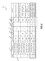
- the simulation script 30 includes one or more steps 40 (e.g., labeled 0-4).
- the steps 40 are defined by one or more fields 42-52.
- the fields 42-52 include data for setting a parameter to a particular value or a series of values.
- the fields 42-52 include for example, but are not limited to a parameter field 42, a set point field 44, a change rate field 46, a duration field 48, a repeat field 50, and a special function field 52.
- the parameter field 42 for example, defines the parameter to be adjusted.
- the set point field 44 for example, defines the value to which the parameter is to be adjusted.
- the change rate field 46 for example, defines the rate at which the parameter is to be changed to achieve the set point value.
- the duration field 48 defines the overall duration of the step which may, in the simplest case, be the time in which the parameter is to hold the set point value.
- the repeat field 50 indicates how many times the set point should be repeated.
- the special function field 52 indicates whether a particular function should be used to adjust the parameter to the set point value.
- the fields of step 0 indicate that each parameter "calibratedAirspeed” should step to 1000 and hold for five seconds, while the parameter "pressureAltitude” should step to 3000 and hold for five seconds.
- the fields of step 1 indicate that the parameter "calibratedAirspeed” should ramp from 1000 to 2000 at a rate of 250 per second and then hold for one second, while the parameter "pressureAltitude” should ramp from 3000 to 2500 at a rate of -100 per second for five seconds.
- the fields of step 2 indicate that the parameter "pressureAltitude” should step to 3000 (with no hold).
- the fields of step 3 indicate that the parameter "pressureAltitude” should sawtooth from 3000 to 2000 five times at a rate of -250 per second (with no hold).
- step 4 indicate that the parameter "calibratedAirspeed" should sinusoid from 2000 to 3000 three times at a three second cycle (with no hold).
- FIG. 2 is merely exemplary in nature, as any number of varying steps can be implemented in the simulation script 30 that relate to any number of parameters of the aircraft 12.
- the onboard maintenance computer 14 receives and processes the simulation script 30.
- the onboard maintenance computer 14 processes the simulation script 30 and determines the simulation parameter values.
- the onboard maintenance computer 14 sends simulation data including a request to the signal producing member system 16 to produce the particular simulated parameter values.
- the onboard maintenance computer 14 processes step 0 of FIG. 2 and generates a plurality of request messages to step the parameter "calibratedAirSpeed" to 1000 and hold for five seconds, and generates a plurality of messages to step the parameter "pressureAltitude" to 3000 and hold for five seconds.
- the onboard maintenance computer 14 processes the simulation script 30 and determines a simulation step 40.
- the onboard maintenance computer 14 generates simulation data including an instruction to the signal producing member systems 16 to interpret and to produce the parameter value or the series of parameter values contained within the step 40.
- the onboard maintenance computer 14 processes step 0 of FIG. 2 and generates an instruction containing data from the fields 42-52 of the step.
- the signal producing member systems 16 receives and interprets the instruction and steps the parameter "calibratedAirSpeed" to 1000 and holds the parameter for five seconds and steps the parameter "pressureAltitude" to 3000 and holds the parameter for five seconds.
- the onboard maintenance computer 14 transmits the entire simulation script 30 or a grouping of steps of the simulation script 30 to the signal producing member system 16.
- the signal producing member system 16 processes the steps of the simulation script 30 to determine the parameter values.
- the onboard maintenance computer 14 generates a test and/or simulation status, and test and/or simulation results.
- the maintenance display 22 receives the results and/or statuses and displays the information for viewing by, for example, maintenance personnel of the aircraft 12.
- the maintenance personnel may interact with the maintenance display 22 to generate start, stop, and continue requests for the test and/or simulation.
- sequence diagrams illustrate simulation methods that may be performed by the simulation system 10 in accordance with various exemplary embodiments.
- the exemplary embodiments shown illustrate simulations methods that may be performed when the onboard maintenance computer (OMC) 14 generates the parameter values for use by the signal producing member system (MS) 16.
- OMC onboard maintenance computer
- MS signal producing member system
- similar methods can be performed when the onboard maintenance computer 14 sends instructions or the entire simulation script 30 as opposed to the parameter values.
- the order of operation within the methods is not limited to the sequential execution as illustrated in FIGS. 3-7 , but may be performed in one or more varying orders as applicable and in accordance with the present disclosure. As can further be appreciated, one or more steps of the methods may be added or removed without altering the spirit of the method.
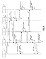
- a sequence diagram illustrates an exemplary sequence that may be performed to initiate the simulation on the aircraft 12.
- a request to begin the simulation is initiated by either a user interacting with the maintenance display 22 or by a user interacting with the cockpit display 24 at 100a, 100b.
- the OMC 14 sends an initiate test request to the MSUT 18 at 102.
- the MSUT 18 may or may not need to be informed about a test. (e.g., because the MSUT 18 is not actually performing a particular test for the simulation).
- the MSUT 18 checks any preconditions for performing the test at 104 and returns any test status codes that result from the preconditions check at 106.
- the MSUT 18 enters the test mode at 108 when the preconditions indicate the test may be entered, and sends the test mode status to the CD 24 at 110.
- the CD 24 displays the test mode at 112.
- the OMC 14 checks the status code returned from the MSUT 18. If the status code indicates not approved to the OMC 14, in other words the MSUT 18 determines the test should not occur, the OMC 14 returns the denied status to the MD 22 at 116 and the MD 22 displays the constraints associated with the status code at 118. Thus, the test and the simulation do not occur.
- the OMC 14 sends an initiate simulation request to the MS 16 at 120.
- the MS 16 checks any preconditions for initiating the simulation at 122 and returns any simulation status codes that result from the preconditions check at 124.
- the MS 16 sends the simulation mode to the CD 24 at 126.
- the CD 24 displays the simulation mode at 128.
- the OMC 14 checks the status code returned from the MS 16. If the status code indicates not approved to the OMC 14, in other words the MS 16 determines the simulation should not occur, the OMC 14 returns the denied status to the MD 22 at 132 and the MD 22 displays the constraints associated with the status code at 134. Thus, the simulation does not occur.
- the status code indicates approval by the MS 16 to the OMC 14, in other words the MS 16 determines that the simulation should occur; the OMC 14 initiates execution of the simulation at 136. Execution of the simulation will be described in further detail with regard to FIGS. 4-7 .
- sequence diagrams illustrate exemplary sequences that may be performed to perform the simulation on the aircraft, once the simulation has been initiated.
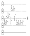
- FIGS. 4 and 5 illustrate the sequences of steps that may occur when conditions of the MS 16 and the MSUT 18 all pass.
- FIGS. 6 and 7 illustrate a sequence of steps that may occur when conditions of the MS 16 and/or the MSUT 18 fail.
- the OMC 14 evaluates the simulation script 30 at 140 to determine the next step 40 of the simulation script 30 (e.g., the OMC 14 begins with step 0, and then proceeds to step 1, and so on).
- the OMC 14 evaluates the data stored in the fields 42-52 of the next step 40 and requests a set point of a particular parameter based on the data at 142.
- the MS 16 checks any conditions for setting the parameter to the set point. If the conditions pass, the MS 16 sets the parameter value based on the set point at 146 and returns the status code to the OMC 14 at 147. If a test is being performed, the MSUT 18 performs all or part of the test at 150. The MSUT 18 checks the test status at 152. If all of the test or part of the test passes, the MSUT 18 returns the test status to the OMC 14 at 154.
- the OMC 14 checks the status code at 158 and checks the test status at 160. When both the status code and the test status indicate that it is ok to proceed, the OMC 14 checks a step status of the simulation script 30 at 162 to determine if the step is complete. If the step status indicates that the step is not complete, then the sequence continues with the OMC 14 requesting the next set point of the current step based on the data of the step, and continues with the steps 144-162. When the step status indicates that the step is complete, the OMC 14 checks a simulation status at 164 to determine if the simulation is complete. If the simulation status indicates that the simulation is not complete, then the sequence continues with the OMC 14 determining the next step at 140 and continues with the steps 142-162.
- the OMC 14 requests a complete test to the MSUT 18 at 166.
- the MSUT 18 determines any test results at 168, exits the test mode at 170, returns a test complete status and/or results to the OMC 14 at 172, and requests a remove test mode to the CD 24 at 174.
- the CD 24 displays the removal of the test mode at 176.
- the OMC 14 sends a simulation complete status to the MS 16.
- the MS 16 returns the parameter to the actual value (e.g., from the sensed value) at 180 and requests a remove simulation mode to the CD 24 at 182.
- the CD 24 displays the removal of the simulation mode at 184.
- the MS 16 returns an acknowledgement to the OMC 14 at 186.
- the OMC 14 provides simulation and/or test results to the MD 22 at 188 and the MD 22 displays the simulation and/or test results at 190. Thereafter, the simulation sequence may end.
- sequence diagrams illustrate exemplary sequences that may be performed to perform the simulation on the aircraft 12, once the simulation has been initiated.
- FIGS. 6 and 7 illustrate a sequence of steps that may occur when conditions of the MS 16 and/or the MSUT 18 fail.
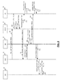
- FIG. 6 illustrates a sequence of steps that may occur when conditions of the MS 16 indicate a simulation failure at the beginning of a test or during a test.
- the OMC 14 evaluates the data from the fields 42-52 of the next step 40 and requests a set point of a particular parameter based on the data at 200.
- the MS 16 checks any conditions for setting the parameter to the set point at 202. If the conditions do not pass, the MS 16 returns the status code(s) to the OMC 14 at 204.
- the OMC 14 checks the status code(s) at 206. When the status code(s) indicates that the conditions did not pass, the OMC 14 sends simulation fail status to the MD 22 at 208.
- the MD 22 displays the simulation fail status at 210.
- the OMC 14 checks the simulation status to determine if the simulation is in progress.
- the OMC 14 requests an abort of the test at 214.
- the MSUT 18 performs operations to abort the test at 216 and returns the test abort status to the OMC 14 at 217.
- the MSUT 18 requests a removal of the test mode of the CD 24 at 218.
- the CD 24 displays the remove the test mode at 220.
- the OMC 14 requests an abort of the simulation by the MS 16.
- the MS 16 returns the parameter to the actual value (e.g., a sensed value) at 224 and returns a simulation abort status acknowledgement to the OMC 14 at 225 and sends a request for removal of the simulation mode to the CD 24 at 226.
- the CD 24 displays the removal of the simulation mode at 228.
- the OMC 14 returns the simulation and/or test status to the MD 22 at 230 and the MD 22 displays the simulation and/or the test results at 232. Thereafter, the simulation sequence may end.
- FIG. 7 illustrates a sequence of steps that may occur when conditions of the MSUT 18 indicate a test failure at a beginning of the test or during the test.
- the OMC 14 evaluates the data from the fields 42-52 of the next step 40 and requests a set point of a particular parameter based on the data at 240.
- the MS 16 checks any conditions for setting the parameter to the set point at 242. If the conditions pass, the MS 16 sets the parameter to the set point at 244. If a test is being performed, the MSUT 18 performs all or part of the test at 248. The MSUT 18 checks the test status at 250. If all of the test or part of the test fails, the MSUT 18 performs operations to abort the test at 252, sends a test fail status to the OMC 14 at 254, and sends a request for removal of the test mode to the CD 24 at 256. The CD 24 displays the removal of the test mode at 258.
- the OMC 14 checks the test status. When the test status indicates a test fail, the OMC 14 requests an abort of the simulation to the MS 16 at 262. The MS 16 returns the parameter to the actual value (e.g., from the sensed value) at 264 and returns an acknowledgement of the abort status at 265. The MS 16 requests for removal of the simulation mode to the CD 24 at 266. The CD 24 displays the removal of the simulation mode at 268. The OMC 14 sends the simulation and/or test results to the MD 22 at 270. The MD 22 displays the simulation and/or test results at 272. Thereafter, the simulation sequence may end.
- the test status indicates a test fail
- the MS 16 requests an abort of the simulation to the MS 16 at 262.
- the MS 16 returns the parameter to the actual value (e.g., from the sensed value) at 264 and returns an acknowledgement of the abort status at 265.
- the MS 16 requests for removal of the simulation mode to the CD 24 at 266.
- the CD 24 displays the removal of the
- one or more steps that are illustrated as being performed by the OMC 14 may similarly be performed by the MS 16.
- the MS 16 when the instructions are sent to the MS 16 for processing or the simulation script 30 is sent to the MS 16 for processing, the MS 16 can perform any one of steps 140, 142, and 158, and 162 of FIG. 4 (in conjunction with the OMC 14 performing the steps) in order to process the data.
- Skilled artisans may implement the described functionality in varying ways for each particular application, but such implementation decisions should not be interpreted as causing a departure from the scope of the present invention.
- an embodiment of a system or a component may employ various integrated circuit components, e.g., memory elements, digital signal processing elements, logic elements, look-up tables, or the like, which may carry out a variety of functions under the control of one or more microprocessors or other control devices.
- integrated circuit components e.g., memory elements, digital signal processing elements, logic elements, look-up tables, or the like, which may carry out a variety of functions under the control of one or more microprocessors or other control devices.
- DSP digital signal processor
- ASIC application specific integrated circuit
- FPGA field programmable gate array
- a general-purpose processor may be a microprocessor, but in the alternative, the processor may be any conventional processor, controller, microcontroller, or state machine.
- a processor may also be implemented as a combination of computing devices, e.g., a combination of a DSP and a microprocessor, a plurality of microprocessors, one or more microprocessors in conjunction with a DSP core, or any other such configuration.
- a software module may reside in RAM memory, flash memory, ROM memory, EPROM memory, EEPROM memory, registers, hard disk, a removable disk, a CD-ROM, or any other form of storage medium known in the art.
- An exemplary storage medium is coupled to the processor such the processor can read information from, and write information to, the storage medium.
- the storage medium may be integral to the processor.
- the processor and the storage medium may reside in an ASIC.
- the ASIC may reside in a user terminal.
- the processor and the storage medium may reside as discrete components in a user terminal.
Landscapes
- Engineering & Computer Science (AREA)
- Physics & Mathematics (AREA)
- General Physics & Mathematics (AREA)
- Automation & Control Theory (AREA)
- Aviation & Aerospace Engineering (AREA)
- Geometry (AREA)
- Human Computer Interaction (AREA)
- Transportation (AREA)
- Manufacturing & Machinery (AREA)
- Theoretical Computer Science (AREA)
- Computational Mathematics (AREA)
- Evolutionary Computation (AREA)
- General Engineering & Computer Science (AREA)
- Computer Hardware Design (AREA)
- Pure & Applied Mathematics (AREA)
- Mathematical Optimization (AREA)
- Mathematical Analysis (AREA)
- Management, Administration, Business Operations System, And Electronic Commerce (AREA)
- Feedback Control In General (AREA)
- Traffic Control Systems (AREA)
- Testing And Monitoring For Control Systems (AREA)
Applications Claiming Priority (1)
| Application Number | Priority Date | Filing Date | Title |
|---|---|---|---|
| US13/827,010 US10055537B2 (en) | 2013-03-14 | 2013-03-14 | Simulation methods and systems for an aircraft |
Publications (2)
| Publication Number | Publication Date |
|---|---|
| EP2778809A2 true EP2778809A2 (de) | 2014-09-17 |
| EP2778809A3 EP2778809A3 (de) | 2016-05-11 |
Family
ID=50236015
Family Applications (1)
| Application Number | Title | Priority Date | Filing Date |
|---|---|---|---|
| EP14158151.2A Withdrawn EP2778809A3 (de) | 2013-03-14 | 2014-03-06 | Simulationsverfahren und Systeme für ein Flugzeug |
Country Status (2)
| Country | Link |
|---|---|
| US (1) | US10055537B2 (de) |
| EP (1) | EP2778809A3 (de) |
Cited By (3)
| Publication number | Priority date | Publication date | Assignee | Title |
|---|---|---|---|---|
| CN114644138A (zh) * | 2022-05-19 | 2022-06-21 | 中国民航大学 | 一种兼具场景重构及故障模拟的飞机通导系统虚拟联调方法 |
| CN114987796A (zh) * | 2022-07-28 | 2022-09-02 | 中国民航大学 | 基于综合模型的飞机座舱显示系统测试系统及方法 |
| CN117349956A (zh) * | 2023-09-11 | 2024-01-05 | 成都飞机工业(集团)有限责任公司 | 一种进气堵锥设计方法、装置、存储介质及电子设备 |
Families Citing this family (5)
| Publication number | Priority date | Publication date | Assignee | Title |
|---|---|---|---|---|
| CN103928985B (zh) * | 2014-04-09 | 2015-10-28 | 国家电网公司 | 基于goose通信机制的联闭锁逻辑自动检测方法 |
| EP2963619A1 (de) * | 2014-06-30 | 2016-01-06 | Airbus Operations GmbH | Datensammelvorrichtung, Datensammelsystem und Verfahren zur Datensammlung in Fahrzeugen |
| CN105205252A (zh) * | 2015-09-11 | 2015-12-30 | 哈尔滨工业大学 | 飞行器姿态控制地面仿真系统效能分析方法 |
| FR3095424B1 (fr) * | 2019-04-23 | 2024-10-04 | Safran | Système et procédé de surveillance d’un moteur d’aéronef |
| CN112937914B (zh) * | 2021-03-08 | 2023-02-03 | 中国航空工业集团公司北京长城航空测控技术研究所 | 一种用于飞行器整机试验的地面模拟指令处理方法 |
Family Cites Families (33)
| Publication number | Priority date | Publication date | Assignee | Title |
|---|---|---|---|---|
| US3678256A (en) * | 1970-10-05 | 1972-07-18 | Mc Donnell Douglas Corp | Performance and failure assessment monitor |
| US5184312A (en) * | 1985-10-13 | 1993-02-02 | The Boeing Company | Distributed built-in test equipment system for digital avionics |
| US5111402A (en) * | 1990-01-19 | 1992-05-05 | Boeing Company | Integrated aircraft test system |
| US5023791A (en) * | 1990-02-12 | 1991-06-11 | The Boeing Company | Automated test apparatus for aircraft flight controls |
| US5671141A (en) * | 1993-04-05 | 1997-09-23 | Ford Global Technologies, Inc. | Computer program architecture for onboard vehicle diagnostic system |
| US5890079A (en) | 1996-12-17 | 1999-03-30 | Levine; Seymour | Remote aircraft flight recorder and advisory system |
| US6499005B2 (en) * | 1997-11-10 | 2002-12-24 | The Boeing Company | System and method for simulating air mode and ground mode of an airplane |
| US6208955B1 (en) * | 1998-06-12 | 2001-03-27 | Rockwell Science Center, Llc | Distributed maintenance system based on causal networks |
| US6606546B2 (en) | 1999-12-01 | 2003-08-12 | Sinex Holdings, Llc | Aircraft maintenance program manager |
| EP1269321B1 (de) | 2000-03-27 | 2008-06-18 | Accenture LLP | Verfahren und system für eine automatische skript basierte lösung zum unternehmenstesten |
| US6799154B1 (en) | 2000-05-25 | 2004-09-28 | General Electric Comapny | System and method for predicting the timing of future service events of a product |
| US6980959B1 (en) | 2000-10-17 | 2005-12-27 | Accenture Llp | Configuring mechanical equipment |
| US6574537B2 (en) * | 2001-02-05 | 2003-06-03 | The Boeing Company | Diagnostic system and method |
| US6789007B2 (en) * | 2001-06-25 | 2004-09-07 | The Boeing Company | Integrated onboard maintenance documentation with a central maintenance system |
| US6622972B2 (en) * | 2001-10-31 | 2003-09-23 | The Boeing Company | Method and system for in-flight fault monitoring of flight control actuators |
| US6751536B1 (en) * | 2002-12-04 | 2004-06-15 | The Boeing Company | Diagnostic system and method for enabling multistage decision optimization for aircraft preflight dispatch |
| US8510083B2 (en) * | 2003-07-31 | 2013-08-13 | The Boeing Company | Method, apparatus and computer program product for constructing a diagnostic network model |
| US7321809B2 (en) * | 2003-12-30 | 2008-01-22 | The Boeing Company | Methods and systems for analyzing engine unbalance conditions |
| US7260501B2 (en) | 2004-04-21 | 2007-08-21 | University Of Connecticut | Intelligent model-based diagnostics for system monitoring, diagnosis and maintenance |
| US8311697B2 (en) * | 2004-07-27 | 2012-11-13 | Honeywell International Inc. | Impact assessment system and method for determining emergent criticality |
| US7510146B2 (en) * | 2004-09-23 | 2009-03-31 | Robert Golden | Window shade system and method of use |
| US7702435B2 (en) * | 2004-11-05 | 2010-04-20 | Honeywell International Inc. | Method and apparatus for system monitoring and maintenance |
| US20060190280A1 (en) * | 2005-02-22 | 2006-08-24 | Lockheed Martin Corporation | Method and apparatus for management for use in fleet service and logistics |
| US7788002B2 (en) * | 2005-08-08 | 2010-08-31 | The Boeing Company | Fault data management |
| FR2898675B1 (fr) * | 2006-03-14 | 2008-05-30 | Thales Sa | Procede d'amelioration de la securite aeronautique relative aux communications air/sol et a l'environnement des aeronefs |
| FR2903384B1 (fr) * | 2006-07-04 | 2009-05-29 | Airbus France Sas | Systeme de commande de vol pour aeronef,et systeme de test pour tester un tel systeme de commande de vol. |
| JP5052519B2 (ja) | 2006-09-29 | 2012-10-17 | 富士通テン株式会社 | シミュレーション装置、シミュレーションシステム及びシミュレーション方法 |
| US8090462B2 (en) | 2007-12-19 | 2012-01-03 | Mobideo Technologies Ltd | Maintenance assistance and control system method and apparatus |
| EP2378468A1 (de) | 2009-11-10 | 2011-10-19 | Airbus Operations GmbH | Plattform für Flugzeugwartungsarbeiten und Anlagenverwaltung |
| US8378853B2 (en) * | 2009-11-18 | 2013-02-19 | Honeywell International Inc. | Intelligent crew alerting system and method for aircraft and other vehicle applications |
| US20110313614A1 (en) * | 2010-06-21 | 2011-12-22 | Hinnant Jr Harris O | Integrated aeroelasticity measurement for vehicle health management |
| FR2970358B1 (fr) * | 2011-01-06 | 2019-04-12 | Airbus Helicopters | Pronostic de duree avant maintenance par fusion entre modelisation et simulation, pour equipements electroniques embarques dans un aeronef |
| US8832497B2 (en) * | 2012-02-07 | 2014-09-09 | A.L.D. Advanced Logistics Development Ltd | Methods, apparatus and systems for performing dynamic fault tree analysis |
-
2013
- 2013-03-14 US US13/827,010 patent/US10055537B2/en not_active Expired - Fee Related
-
2014
- 2014-03-06 EP EP14158151.2A patent/EP2778809A3/de not_active Withdrawn
Non-Patent Citations (1)
| Title |
|---|
| None |
Cited By (5)
| Publication number | Priority date | Publication date | Assignee | Title |
|---|---|---|---|---|
| CN114644138A (zh) * | 2022-05-19 | 2022-06-21 | 中国民航大学 | 一种兼具场景重构及故障模拟的飞机通导系统虚拟联调方法 |
| CN114644138B (zh) * | 2022-05-19 | 2022-08-05 | 中国民航大学 | 一种兼具场景重构及故障模拟的飞机通导系统虚拟联调方法 |
| CN114987796A (zh) * | 2022-07-28 | 2022-09-02 | 中国民航大学 | 基于综合模型的飞机座舱显示系统测试系统及方法 |
| CN114987796B (zh) * | 2022-07-28 | 2022-10-21 | 中国民航大学 | 基于综合模型的飞机座舱显示系统测试系统及方法 |
| CN117349956A (zh) * | 2023-09-11 | 2024-01-05 | 成都飞机工业(集团)有限责任公司 | 一种进气堵锥设计方法、装置、存储介质及电子设备 |
Also Published As
| Publication number | Publication date |
|---|---|
| US10055537B2 (en) | 2018-08-21 |
| US20140278313A1 (en) | 2014-09-18 |
| EP2778809A3 (de) | 2016-05-11 |
Similar Documents
| Publication | Publication Date | Title |
|---|---|---|
| US10055537B2 (en) | Simulation methods and systems for an aircraft | |
| US10467363B2 (en) | Fault simulation system | |
| EP3407200A1 (de) | Verfahren und vorrichtung zur aktualisierung eines selbstlernenden online-modells für ereigniserkennung | |
| KR100921503B1 (ko) | 무인 철도 시스템 운영 시뮬레이션을 이용한 훈련 시스템및 그 방법 | |
| WO2010151732A4 (en) | Method and system for rating device security and automatically assessing security compliance | |
| US10657608B2 (en) | Engineering change management system | |
| CN107608291A (zh) | 一种智能变电站应用功能联动规则验证方法及系统 | |
| RU2627935C2 (ru) | Способ и устройство для разработки системы для управления предупреждениями и процедурами на летательном аппарате | |
| CN113220518A (zh) | 芯片验证系统、芯片验证方法 | |
| CN104461651A (zh) | 一种框架流程控制方法、装置及系统 | |
| EP3474509B1 (de) | Verfahren zur steuerung einer vorrichtung und steuerungssystem | |
| CN113126881B (zh) | 系统配置方法、装置、设备、可读存储介质及分布式存储系统 | |
| US20170351238A1 (en) | Checking a functional module of an automation installation | |
| US20200074375A1 (en) | Product maturity determination in a technical system and in particular in an autonomously driving vehicle | |
| CN115755824A (zh) | 区域控制器的测试方法及装置 | |
| CN111975172B (zh) | 用于电弧焊机的交互方法、交互系统及电弧焊机交互设备 | |
| EP3321808A1 (de) | Verifizierungssystem und verifizierungsverfahren | |
| CN100559423C (zh) | 设备模拟器 | |
| CN114416445B (zh) | 压力测试方法、装置和电子设备 | |
| US10013266B2 (en) | System and method for executing operations specified in a procedure language | |
| CN105302570B (zh) | 芯片编程的控制方法和系统 | |
| CN104537893B (zh) | 一种民航驾驶员飞行行为监视系统及监视方法 | |
| CN108845945A (zh) | 应用测试优化方法及装置 | |
| CN115587496A (zh) | 基于车路协同的测试方法、装置、设备、系统及存储介质 | |
| CN116566627B (zh) | 密钥学习的测试方法、系统、装置、设备及可读存储介质 |
Legal Events
| Date | Code | Title | Description |
|---|---|---|---|
| 17P | Request for examination filed |
Effective date: 20140306 |
|
| AK | Designated contracting states |
Kind code of ref document: A2 Designated state(s): AL AT BE BG CH CY CZ DE DK EE ES FI FR GB GR HR HU IE IS IT LI LT LU LV MC MK MT NL NO PL PT RO RS SE SI SK SM TR |
|
| AX | Request for extension of the european patent |
Extension state: BA ME |
|
| PUAI | Public reference made under article 153(3) epc to a published international application that has entered the european phase |
Free format text: ORIGINAL CODE: 0009012 |
|
| RAP1 | Party data changed (applicant data changed or rights of an application transferred) |
Owner name: HONEYWELL INTERNATIONAL INC. |
|
| PUAL | Search report despatched |
Free format text: ORIGINAL CODE: 0009013 |
|
| AK | Designated contracting states |
Kind code of ref document: A3 Designated state(s): AL AT BE BG CH CY CZ DE DK EE ES FI FR GB GR HR HU IE IS IT LI LT LU LV MC MK MT NL NO PL PT RO RS SE SI SK SM TR |
|
| AX | Request for extension of the european patent |
Extension state: BA ME |
|
| RIC1 | Information provided on ipc code assigned before grant |
Ipc: G05B 17/02 20060101AFI20160401BHEP Ipc: G05B 23/02 20060101ALI20160401BHEP |
|
| 17Q | First examination report despatched |
Effective date: 20160607 |
|
| RIC1 | Information provided on ipc code assigned before grant |
Ipc: G06F 17/50 20060101AFI20180913BHEP Ipc: G05B 17/02 20060101ALI20180913BHEP Ipc: B64F 5/60 20170101ALI20180913BHEP Ipc: G05B 23/02 20060101ALI20180913BHEP |
|
| GRAP | Despatch of communication of intention to grant a patent |
Free format text: ORIGINAL CODE: EPIDOSNIGR1 |
|
| INTG | Intention to grant announced |
Effective date: 20190326 |
|
| STAA | Information on the status of an ep patent application or granted ep patent |
Free format text: STATUS: THE APPLICATION IS DEEMED TO BE WITHDRAWN |
|
| 18D | Application deemed to be withdrawn |
Effective date: 20190806 |