EP2778824A2 - Conditionneur de puissance et programme - Google Patents
Conditionneur de puissance et programme Download PDFInfo
- Publication number
- EP2778824A2 EP2778824A2 EP13188790.3A EP13188790A EP2778824A2 EP 2778824 A2 EP2778824 A2 EP 2778824A2 EP 13188790 A EP13188790 A EP 13188790A EP 2778824 A2 EP2778824 A2 EP 2778824A2
- Authority
- EP
- European Patent Office
- Prior art keywords
- power supply
- inverter
- power
- boost circuit
- voltage
- Prior art date
- Legal status (The legal status is an assumption and is not a legal conclusion. Google has not performed a legal analysis and makes no representation as to the accuracy of the status listed.)
- Withdrawn
Links
- 238000000034 method Methods 0.000 claims description 9
- 239000003990 capacitor Substances 0.000 description 13
- 239000004065 semiconductor Substances 0.000 description 7
- 238000003491 array Methods 0.000 description 2
- 230000015556 catabolic process Effects 0.000 description 2
- 230000003247 decreasing effect Effects 0.000 description 2
- 238000006731 degradation reaction Methods 0.000 description 2
- 238000010586 diagram Methods 0.000 description 2
- 238000012986 modification Methods 0.000 description 2
- 230000004048 modification Effects 0.000 description 2
- 230000002411 adverse Effects 0.000 description 1
- 238000004891 communication Methods 0.000 description 1
- 238000009413 insulation Methods 0.000 description 1
- 230000015654 memory Effects 0.000 description 1
- 230000004044 response Effects 0.000 description 1
- 230000001360 synchronised effect Effects 0.000 description 1
- 238000004804 winding Methods 0.000 description 1
Images


Classifications
-
- G—PHYSICS
- G05—CONTROLLING; REGULATING
- G05F—SYSTEMS FOR REGULATING ELECTRIC OR MAGNETIC VARIABLES
- G05F1/00—Automatic systems in which deviations of an electric quantity from one or more predetermined values are detected at the output of the system and fed back to a device within the system to restore the detected quantity to its predetermined value or values, i.e. retroactive systems
- G05F1/66—Regulating electric power
- G05F1/67—Regulating electric power to the maximum power available from a generator, e.g. from solar cell
Definitions
- the present invention relates to a power conditioner and a program.
- a maximum power estimated value of a photovoltaic module is estimated based on power inputted to a converter and a voltage accumulated in a capacitor, the maximum power estimated value is compared to a start-up determination value, and whether a power conditioner is started up is determined based on a comparison result.
- a power conditioner includes: a boost circuit configured to boost a voltage outputted from a power supply; an inverter configured to convert a direct current outputted from the boost circuit into an alternating current and to output the alternating current to a load or a system power supply; a cutoff unit configured to switch whether the inverter is electrically cut off from the system power supply or the load; a controller configured to control operations of the inverter; a start-up determination unit configured to determine whether a startable power is obtained from the power supply when the voltage output from the power supply is greater than or equal to a reference voltage while the controller operates the boost circuit and the inverter and the inverter is electrically cut off from the system power supply or the load through the cutoff unit; and a cutoff controller configured to electrically connect the inverter and the load or the system power supply through the cutoff unit when the start-up determination unit determines that the startable power is obtained from the power supply.
- the start-up determination unit may determine whether the startable power is obtained from the power supply by causing the controller to operate the inverter and the boost circuit, when the voltage outputted from the boost circuit is less than an upper-limit voltage higher than the reference voltage while the inverter is electrically cut off from the system power supply or the load through the cutoff unit.
- the start-up determination unit may determine that the startable power is obtained from the power supply, when the voltage outputted from the boost circuit is greater than or equal to the startable voltage while power outputted from the boost circuit reaches reference power.
- a program configured to cause a computer to act as a control device making a start-up determination of a power conditioner, the power conditioner comprising: a boost circuit configured to boost a voltage outputted from a power supply; an inverter configured to convert a direct current output from the boost circuit into an alternating current and to output the alternating current to a load or a system power supply; and a cutoff unit configured to switch whether the inverter is electrically cut off from the system power supply or the load, the program causes the computer to act as: a controller configured to control operations of the boost circuit and the inverter; a start-up determination unit configured to determine whether a startable power is obtained from the power supply when the controller operates the inverter and the voltage outputted from the power supply is greater than or equal to a reference voltage while the inverter is electrically cut off from the system power supply or the load through the cutoff unit; and a cutoff controller configured to electrically connect the inverter and the load or the system power supply through the
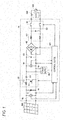
- Fig. 1 is a system configuration diagram illustrating an example of an entire configuration of a photovoltaic system of the present embodiment.
- the photovoltaic system includes a photovoltaic array 200 and a power conditioner 10.
- a plurality of photovoltaic strings in which a plurality of photovoltaic modules are connected in series are connected in parallel in the photovoltaic array 200.
- the plurality of photovoltaic arrays 200 are examples of the power supply that outputs a DC voltage.
- the power conditioner 10 boosts the DC voltage outputted from the photovoltaic array 200, converts the boosted DC voltage into an AC voltage, and outputs the AC voltage onto a side of a system power supply 300.
- the power conditioner 10 includes a capacitor C1, a boost circuit 20, a capacitor C2, an inverter 40, a coil L2, a capacitor C3, a relay 50, a power supply 60, and a control device 100.
- the boost circuit 20 includes a coil L1, a switch Tr, and a diode D1.
- the boost circuit 20 may be what is called a chopper switching regulator.
- the boost circuit 20 boosts the voltage outputted from the photovoltaic array 200.
- the switch Tr is an Insulated Gate Bipolar Transistor (IGBT).
- IGBT Insulated Gate Bipolar Transistor
- One end of the coil L1 is connected to one end of the capacitor C1, and the other end of the coil L1 is connected to a collector of the switch Tr.
- the collector of the switch Tr is connected to an anode of the diode D1, and an erraitter of the switch Tr is connected to the other end of the capacitor C1.
- the coil L1 accumulates energy based on power outputted from the photovoltaic array 200 during an on period of the switch Tr, and discharges the energy during an off period of the switch Tr. Therefore, the boost circuit 20 boosts the DC voltage outputted from the photovoltaic array 200.
- the diode D1 rectifies the output from the coil L1.
- the diode D1 prevents the boosted DC voltage from flowing onto an input side from an output side of the boost circuit 20.
- the boost circuit 20 is not limited to the above configuration.
- the boost circuit 20 may be constructed by insulation type boost circuits, such as a half-bridge boost circuit and a full-bridge boost circuit, which have a transformer winding.
- the capacitor C2 smoothes the DC voltage outputted from the boost circuit 20.
- the inverter 40 includes a switch, and converts the DC voltage outputted from the boost circuit 20 into the AC voltage by turning on and off the switch to output to the system power supply 300 or a load 310.
- the inverter 40 may be constructed by a single-phase full-bridge PWM inverter including four bridge-connected semiconductor switches. In one pair out of the four semiconductor switches, the semiconductor switches are connected in series. In the other pair out of the four semiconductor switches, the semiconductor switches are connected in series. The other pair of the semiconductor switches is connected in parallel to the one pair of the semiconductor switches.
- the coil L2 and the capacitor C3 are provided between the inverter 40 and the system power supply 300.
- the coil L2 and the capacitor C3 remove a noise from the AC voltage outputted from the inverter 40.
- the relay 50 is provided between the capacitor C3 and the system power supply 300.
- the relay 50 switches whether the inverter 40 is electrically cut off from the system power supply 300 or the load 310.
- the power conditioner 10 is electrically connected to the system power supply 300 or the load 310 by turning on the relay 50, and the power conditioner 10 is electrically cut off from the system power supply 300 or the load 310 by turning off the relay 50.
- the relay 50 is an example of the cutoff unit.
- the power supply 60 is constructed by a power supply IC chip.
- the power supply 60 is connected onto an output side of the boost circuit 20.
- the power supply 60 generates power, which indicates a predetermined voltage supplied to the control device 100, from the DC voltage taken out from the boost circuit 20, and the power supply 60 supplies the generated power to the control device 100.
- the power supply 60 is started up, when the voltage outputted from the boost circuit 20 reaches a reference voltage while the switch Tr of the boost circuit 20 is in an off state. After the start-up, the power supply 60 generates driving power driving the control device 100 using the power outputted from the boost circuit 20, and supplies the driving power to the control device 100.
- the power supply 60 may directly use the power from the system power supply 300 to generate the power supplied to the control device 100.
- the control device 100 controls the switching operation of the boost circuit 20, boosts the DC voltage outputted from the photovoltaic array 200, converts the boosted DC voltage into the AC voltage, and outputs the AC voltage onto the side of the system power supply 300.
- the power conditioner 10 also includes voltage sensors 12 and 16 and current sensors 14 and 18.
- the voltage sensor 12 detects a voltage Vin corresponding to a potential difference between both the ends of the photovoltaic array 200.
- the voltage sensor 16 detects a voltage Vout corresponding to the potential difference between both the ends on the output side of the boost circuit 20.
- the current sensor 14 detects a current lin, which is outputted from the photovoltaic array 200 and passes onto the input side of the boost circuit 20.
- the current sensor 18 detects a current Iout outputted from the boost circuit 20.
- Fig. 2 is a flowchart illustrating an example of a processing procedure performed during the start-up of the control device 100.
- the power supply 60 is started up, when an output voltage Vout, which is inputted from the photovoltaic array 200 and outputted from the boost circuit 20, is greater than or equal to a reference voltage Vth1 while the boost circuit 20, the inverter 40, the power supply 60, and the control device 100 are stopped (S10).
- the power supply 60 generates the driving power driving the control device 100 using the power outputted from the photovoltaic array 200.
- the control device 100 is started up by receiving the power from the power supply 60 (S12).
- the control device 100 starts the operation of the boost circuit 20 while the inverter 40 is electrically cut off from the system power supply 300 or the load 310 through the relay 50 (S14).
- the control device 100 estimates power Wa that can be outputted from the boost circuit 20 with an amount of change in power, which is outputted from the boost circuit 20 when the voltage input to the boost circuit 20 is changed, as a parameter (S16).
- the control device 100 determines whether the power Wa is greater than or equal to power Wt necessary to operate the control device 100, the boost circuit 20, and the inverter 40 (S18). When the power Wa is less than the power Wt, the control device 100 determines that the power obtained from the photovoltaic array 200 does not satisfy the power necessary to start up the power conditioner 10, and stops the operation of the boost circuit 20 (S20). The control device 100 starts the operation of the boost circuit 20 again when a predetermined waiting period elapses (S22).
- the control device 100 turns on the relay 50 (S24), and starts the operation of the inverter 40 to start grid interconnection with the system power supply 300 (S26).
- the control device 100 turns on the relay 50 to operate the inverter 40, when the estimated power satisfies the power that can operate the control device 100, the boost circuit 20, and the inverter 40.
- the control device 100 stops the operations of the boost circuit 20 and the inverter 40 to tentatively turn off the relay 50. Then the control device 100 starts the operation of the boost circuit 20 to estimate the power again.
- the relay 50 is repeatedly turned on and off by repeating the estimation of the power during the start-up of the power conditioner 10. Because occasionally the obtained power changes depending on the type of the photovoltaic array connected to the power conditioner 10, it is further difficult that the control device 100 accurately estimates the power for many types of the photovoltaic arrays that can be connected to the power conditioner 10.
- the control device 100 determines whether a startable power corresponding to the minimum power necessary to start up the power conditioner 10 is obtained from the photovoltaic array 200 based on the power outputted from the boost circuit 20. Therefore, the accuracy of the start-up determination of the power conditioner 10 can be improved. Additionally, the turn-on and -off repetitions of the relay 50, which are caused by repeating the estimation of the power during the start-up of the power conditioner 10, can be prevented. Therefore, a generation frequency of an operating sound caused by turning on and off the relay 50 can be decreased. Additionally, progression of degradation of the relay 50 due to the turn-on and -off of the relay 50 can be reduced.
- Fig. 3 illustrates an example of a functional block of the control device 100 of the present embodiment.
- the control device 100 includes a controller 102, a relay controller 104, and a start-up determination unit 106.
- the controller 102 controls the operations of the boost circuit 20 and the inverter 40.
- the controller 102 controls a boost ratio by turning on and off the switch Tr included in the boost circuit 20 based on PWM control, and controls an input voltage Vin at the boost circuit 20 such that the maximum pr peak power is obtained from the photovoltaic array 200.
- the controller 102 controls the input voltage at the inverter 40 by turning on and off each switch included in the inverter 40 based on the PWM control, and converts the direct current outputted from the boost circuit 20 into the alternating current synchronized with the voltage at the system power supply 300.
- the relay controller 104 turns on and off the relay 50 to perform the electric connection and cutoff between the inverter 40 and the system power supply 300 or the load 310.
- the start-up determination unit 106 causes the controller 102 to operate the boost circuit 20 and the inverter 40 while the inverter 40 is electrically cut off from the system power supply 300 or the load 310 through the relay 50.
- the start-up determination unit 106 determines whether the startable power is obtained from the photovoltaic array 200 while the boost circuit 20 and the inverter 40 are operated.
- the start-up determination unit 106 may determine that the startable power is obtained from the photovoltaic array 200 when the voltage outputted from the boost circuit 20 is greater than or equal to a startable voltage Vth3 while the power outputted from the boost circuit 20 reaches the reference power Wth (Step S110 in Fig. 3 ).
- the controller 102 operates the inverter 40 while the relay 50 is turned off in order that the start-up determination unit 106 more accurately determines whether the power necessary to start up the inverter 40, in addition to the control device 100 and the boost circuit 20, is obtained from the photovoltaic array 200. Accordingly, the controller 102 may control each switch of the inverter 40 to operate the inverter 40 on an arbitrary condition. For example, the controller 102 may operate the inverter 40 by controlling each switch of the inverter 40 at a duty ratio of 50%. A processing burden on the control device 100 can be reduced by controlling each switch of the inverter 40 at the duty ratio of 50%.
- the relay controller 104 electrically connects the inverter 40 and the system power supply 300 or the load 310 through the relay 50 in response to the result that the start-up determination unit 106 determines that the startable power is obtained from the photovoltaic array 200.
- the photovoltaic array 200 When the photovoltaic array 200 outputs the high voltage, occasionally the voltage outputted from the boost circuit 20 is excessively high in the case where the boost circuit 20 is operated. In such cases, possibly elements, such as the capacitor C2, which are provided on the output side of the boost circuit 20 are adversely affected.
- the start-up determination unit 106 may cause the controller 102 to operate the inverter 40 while the inverter 40 is electrically cut off from the system power supply 300 or the load 310 through the relay 50 (Steps S104 and S108 in Fig. 4 ).
- the start-up determination unit 106 may determine whether the startable power is obtained from the photovoltaic array 200, in the state in which the boost operation of the boost circuit 20 is stopped while the on and off operations of the switch of the inverter 40 are performed (Step S110 in Fig. 3 ).
- the start-up determination unit 106 may stop the boost operation of the boost circuit 20 while performing only the on and off operations of the switch of the inverter 40, and the start-up determination unit 106 may determine whether the startable power is obtained from the photovoltaic array 200.
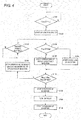
- Fig. 4 is a flowchart illustrating a procedure in which the control device 100 makes the start-up determination of the power conditioner 10.
- the power supply 60 is started up, when the output voltage Vout, which is inputted from the photovoltaic array 200 and outputted from the boost circuit 20, is greater than or equal to the reference voltage Vth1 while the boost circuit 20, the inverter 40, the power supply 60, and the control device 100 are stopped.
- the power supply 60 generates the driving power driving the control device 100 using the power output from the photovoltaic array 200.
- the control device 100 is started up by receiving the power from the power supply 60 (S102).
- the start-up determination unit 106 determines whether the output voltage Vout at the boost circuit 20 is greater than or equal to the upper-limit voltage Vth2 (S104). When the output voltage Vout is less than the upper-limit voltage Vth2, the start-up determination unit 106 causes the controller 102 to start the operations of the boost circuit 20 and the inverter 40 while the inverter 40 is electrically cut off from the system power supply 300 or the load 310 through the relay 50 (S106). The controller 102 may start the on and off operations of each of the switches included in the boost circuit 20 and the inverter 40.
- the start-up determination unit 106 calculates the power Wout outputted from the boost circuit 20 based on the voltage Vout and the current Iout, which are outputted from the boost circuit 20. The start-up determination unit 106 determines whether the output voltage Vout at the boost circuit is greater than or equal to the startable voltage Vth3 when the power Wout reaches the reference power Wth(S110). When the output voltage Vout is greater than or equal to the startable voltage Vth3, the start-up determination unit 106 determines that the startable power is obtained from the photovoltaic array 200, the controller 102 tentatively stops the operation of the inverter 40 (S112), and the relay controller 104 turns on the relay 50 (S114).
- the controller 102 After the relay controller 104 turns on the relay 50, the controller 102 starts the operation of the inverter 40 again (S116). In the case where the power conditioner 10 is not interconnected with the system power supply 300, the controller 102 may not tentatively stop the inverter 40 before the relay 50 is turned on.
- the start-up determination unit 106 causes the controller 102 to start the operation of the inverter 40, in the state in which the boost circuit 20 is stopped while the inverter 40 is electrically cut off from the system power supply 300 or the load 310 through the relay 50 (S108).
- the start-up determination unit 106 determines whether the output voltage Vout at the boost circuit is greater than or equal to the startable voltage Vth3 when the power Wout reaches the reference power Wth (S110).
- the start-up determination unit 106 causes the controller 102 to stop the operations of the boost circuit 20 and the inverter 40 or the operation of the inverter 40 (S118).
- a predetermined waiting period elapses after the operations of the boost circuit 20 and the inverter 40 or the operation of the inverter 40 is stopped (S120)
- the start-up determination unit 106 performs the pieces of processing from Step S104 again.
- the power conditioner 10 makes the start-up determination
- the power output from the photovoltaic array 200 is estimated while the inverter 40 is operated, and the start-up determination can be made from the estimated power. Accordingly, the start-up determination can accurately be made irrespective of the type of the photovoltaic array 200 connected to the power conditioner 10. Therefore, the turn-on and -off repetitions of the relay 50, which are caused by repeating the estimation of the power during the start-up of the power conditioner 10, can be prevented. Additionally, the generation frequency of the operating sound caused by turning on and off the relay 50 can be decreased, and progression of degradation of the relay 50 due to the turn-on and -off of the relay 50 can be reduced.
- Each unit included in the control device 100 of the present embodiment may be constructed by installing a program, which is recorded in a computer-readable recording medium to perform various pieces of processing related to the start-up determination of the power conditioner 10, and by causing the computer to execute the program. That is, the computer acts as each unit included in the control device 100 by causing the computer to execute the program, which performs various pieces of processing related to the start-up determination of the power conditioner 10, whereby the control device 100 may be constructed.
- the computer includes a CPU, various memories such as a ROM, a RAM, and an EEPROM (registered trademark), a communication bus, and an intorface, and the CPU reads and executes sequentially the processing program previously stored in the ROM as firmware, whereby the computer acts as the control device 100.
- various memories such as a ROM, a RAM, and an EEPROM (registered trademark)
- a communication bus and an intorface
Landscapes
- Engineering & Computer Science (AREA)
- Life Sciences & Earth Sciences (AREA)
- Sustainable Development (AREA)
- Sustainable Energy (AREA)
- Power Engineering (AREA)
- Physics & Mathematics (AREA)
- Electromagnetism (AREA)
- General Physics & Mathematics (AREA)
- Radar, Positioning & Navigation (AREA)
- Automation & Control Theory (AREA)
- Inverter Devices (AREA)
- Supply And Distribution Of Alternating Current (AREA)
Applications Claiming Priority (1)
| Application Number | Priority Date | Filing Date | Title |
|---|---|---|---|
| JP2013054146A JP6119332B2 (ja) | 2013-03-15 | 2013-03-15 | パワーコンディショナおよびプログラム |
Publications (2)
| Publication Number | Publication Date |
|---|---|
| EP2778824A2 true EP2778824A2 (fr) | 2014-09-17 |
| EP2778824A3 EP2778824A3 (fr) | 2014-09-24 |
Family
ID=49385120
Family Applications (1)
| Application Number | Title | Priority Date | Filing Date |
|---|---|---|---|
| EP13188790.3A Withdrawn EP2778824A3 (fr) | 2013-03-15 | 2013-10-15 | Conditionneur de puissance et programme |
Country Status (2)
| Country | Link |
|---|---|
| EP (1) | EP2778824A3 (fr) |
| JP (1) | JP6119332B2 (fr) |
Cited By (4)
| Publication number | Priority date | Publication date | Assignee | Title |
|---|---|---|---|---|
| CN104701885A (zh) * | 2015-04-02 | 2015-06-10 | 深圳市英威腾电气股份有限公司 | 光伏并网逆变器启动方法及控制系统 |
| CN107850914A (zh) * | 2015-09-09 | 2018-03-27 | 株式会社日立产机系统 | 功率调节器和功率调节器的控制方法 |
| US11495966B2 (en) | 2017-08-31 | 2022-11-08 | Murata Manufacturing Co., Ltd. | Solar power generation system and power conditioner |
| CN117674098A (zh) * | 2023-11-29 | 2024-03-08 | 国网浙江省电力有限公司丽水供电公司 | 面向不同渗透率的多元负荷时空概率分布预测方法及系统 |
Citations (2)
| Publication number | Priority date | Publication date | Assignee | Title |
|---|---|---|---|---|
| JP2009247184A (ja) | 2008-03-31 | 2009-10-22 | Mitsubishi Electric Corp | 太陽光発電システムおよびその起動方法 |
| US20150295512A1 (en) * | 2014-04-15 | 2015-10-15 | Fronius International Gmbh | Method for feeding energy from photovoltaic modules of a photovoltaic system and inverter designed for executing this method |
Family Cites Families (6)
| Publication number | Priority date | Publication date | Assignee | Title |
|---|---|---|---|---|
| JPS5292324A (en) * | 1976-01-30 | 1977-08-03 | Nippon Telegr & Teleph Corp <Ntt> | Three phase inverter |
| JP3373896B2 (ja) * | 1993-07-06 | 2003-02-04 | 三洋電機株式会社 | 太陽電池電源 |
| JP2002271991A (ja) * | 2001-03-14 | 2002-09-20 | Kyocera Corp | 太陽光発電システム、太陽光発電システムの起動方法、及びコンピュータ読み取り可能な記録媒体 |
| JP4511127B2 (ja) * | 2003-02-26 | 2010-07-28 | 京セラ株式会社 | 太陽光発電システム |
| JP5071498B2 (ja) * | 2010-03-10 | 2012-11-14 | オムロン株式会社 | 電力変換装置およびパワーコンディショナ |
| DE102010060633B3 (de) * | 2010-11-17 | 2012-04-26 | Sma Solar Technology Ag | Verfahren zum Verbinden einer Photovoltaikanlage mit einem Stromversorgungsnetz und Photovoltaikanlage zur Durchführung des Verfahrens |
-
2013
- 2013-03-15 JP JP2013054146A patent/JP6119332B2/ja active Active
- 2013-10-15 EP EP13188790.3A patent/EP2778824A3/fr not_active Withdrawn
Patent Citations (2)
| Publication number | Priority date | Publication date | Assignee | Title |
|---|---|---|---|---|
| JP2009247184A (ja) | 2008-03-31 | 2009-10-22 | Mitsubishi Electric Corp | 太陽光発電システムおよびその起動方法 |
| US20150295512A1 (en) * | 2014-04-15 | 2015-10-15 | Fronius International Gmbh | Method for feeding energy from photovoltaic modules of a photovoltaic system and inverter designed for executing this method |
Cited By (7)
| Publication number | Priority date | Publication date | Assignee | Title |
|---|---|---|---|---|
| CN104701885A (zh) * | 2015-04-02 | 2015-06-10 | 深圳市英威腾电气股份有限公司 | 光伏并网逆变器启动方法及控制系统 |
| CN107850914A (zh) * | 2015-09-09 | 2018-03-27 | 株式会社日立产机系统 | 功率调节器和功率调节器的控制方法 |
| EP3349091A4 (fr) * | 2015-09-09 | 2019-05-08 | Hitachi Industrial Equipment Systems Co., Ltd. | Conditionneur d'énergie et procédé de commande de conditionneur d'énergie |
| CN107850914B (zh) * | 2015-09-09 | 2020-04-24 | 株式会社日立产机系统 | 功率调节器和功率调节器的控制方法 |
| US11495966B2 (en) | 2017-08-31 | 2022-11-08 | Murata Manufacturing Co., Ltd. | Solar power generation system and power conditioner |
| CN117674098A (zh) * | 2023-11-29 | 2024-03-08 | 国网浙江省电力有限公司丽水供电公司 | 面向不同渗透率的多元负荷时空概率分布预测方法及系统 |
| CN117674098B (zh) * | 2023-11-29 | 2024-06-07 | 国网浙江省电力有限公司丽水供电公司 | 面向不同渗透率的多元负荷时空概率分布预测方法及系统 |
Also Published As
| Publication number | Publication date |
|---|---|
| JP6119332B2 (ja) | 2017-04-26 |
| JP2014180182A (ja) | 2014-09-25 |
| EP2778824A3 (fr) | 2014-09-24 |
Similar Documents
| Publication | Publication Date | Title |
|---|---|---|
| US10090709B2 (en) | Bidirectional non-contact power supply device and bidirectional non-contact power supply system | |
| EP2768132B1 (fr) | Conditionneur d'énergie, système photovoltaïque et procédé de détermination d'anomalie | |
| US20130016531A1 (en) | Power supply device and method of controlling power supply device | |
| EP2760118B1 (fr) | Conditionneur d'énergie, système photovoltaïque et procédé de détermination d'anomalie | |
| US9602007B2 (en) | Power conversion apparatus | |
| US10084383B2 (en) | Booster device and converter device | |
| JP6300664B2 (ja) | 鉄道車両用電源回路 | |
| EP2778824A2 (fr) | Conditionneur de puissance et programme | |
| JP5252214B2 (ja) | スイッチング電源装置 | |
| US9252678B2 (en) | Power conversion apparatus | |
| JP2010252512A (ja) | Dcdcコンバータの制御装置及び制御システム | |
| EP2765472B1 (fr) | Unité de survoltage, onduleur, système photovoltaïque, programme et procédé de suivi de tension | |
| JP2014155384A (ja) | 電力変換装置 | |
| JP5355655B2 (ja) | Dcdcコンバータおよびdcdcコンバータの制御方法 | |
| US10734900B2 (en) | Converter device, motor drive device, refrigerator, air conditioner, and heat-pump water heater | |
| CN117375381B (zh) | Dc/dc变换器及其控制方法、功率变换装置和储能系统 | |
| CN109792211A (zh) | 电能系统中的部分功率转换器(ppc) | |
| US20230124775A1 (en) | Power supply circuit | |
| JP7578004B2 (ja) | 電圧変換装置 | |
| JP6444204B2 (ja) | 電力変換装置 | |
| US10468992B2 (en) | Auxiliary power supply device for electric rolling stock | |
| JP5381169B2 (ja) | Dc−dcコンバータ | |
| CN109004675B (zh) | 一种自适应切换绕组的宽输入辅助电源 | |
| US9948189B2 (en) | Power conversion device and method for correcting decision threshold level thereof | |
| TWI556461B (zh) | 電源系統的電能輸出控制方法 |
Legal Events
| Date | Code | Title | Description |
|---|---|---|---|
| PUAL | Search report despatched |
Free format text: ORIGINAL CODE: 0009013 |
|
| PUAI | Public reference made under article 153(3) epc to a published international application that has entered the european phase |
Free format text: ORIGINAL CODE: 0009012 |
|
| 17P | Request for examination filed |
Effective date: 20131015 |
|
| AK | Designated contracting states |
Kind code of ref document: A2 Designated state(s): AL AT BE BG CH CY CZ DE DK EE ES FI FR GB GR HR HU IE IS IT LI LT LU LV MC MK MT NL NO PL PT RO RS SE SI SK SM TR |
|
| AX | Request for extension of the european patent |
Extension state: BA ME |
|
| AK | Designated contracting states |
Kind code of ref document: A3 Designated state(s): AL AT BE BG CH CY CZ DE DK EE ES FI FR GB GR HR HU IE IS IT LI LT LU LV MC MK MT NL NO PL PT RO RS SE SI SK SM TR |
|
| AX | Request for extension of the european patent |
Extension state: BA ME |
|
| RIC1 | Information provided on ipc code assigned before grant |
Ipc: G05F 1/67 20060101AFI20140819BHEP |
|
| R17P | Request for examination filed (corrected) |
Effective date: 20150324 |
|
| RBV | Designated contracting states (corrected) |
Designated state(s): AL AT BE BG CH CY CZ DE DK EE ES FI FR GB GR HR HU IE IS IT LI LT LU LV MC MK MT NL NO PL PT RO RS SE SI SK SM TR |
|
| STAA | Information on the status of an ep patent application or granted ep patent |
Free format text: STATUS: EXAMINATION IS IN PROGRESS |
|
| 17Q | First examination report despatched |
Effective date: 20171017 |
|
| STAA | Information on the status of an ep patent application or granted ep patent |
Free format text: STATUS: THE APPLICATION IS DEEMED TO BE WITHDRAWN |
|
| 18D | Application deemed to be withdrawn |
Effective date: 20180228 |