EP2779103A2 - Wiedergabeeinrichtungsgrafik - Google Patents
Wiedergabeeinrichtungsgrafik Download PDFInfo
- Publication number
- EP2779103A2 EP2779103A2 EP14159918.3A EP14159918A EP2779103A2 EP 2779103 A2 EP2779103 A2 EP 2779103A2 EP 14159918 A EP14159918 A EP 14159918A EP 2779103 A2 EP2779103 A2 EP 2779103A2
- Authority
- EP
- European Patent Office
- Prior art keywords
- node
- objects
- subset
- animation objects
- animation
- Prior art date
- Legal status (The legal status is an assumption and is not a legal conclusion. Google has not performed a legal analysis and makes no representation as to the accuracy of the status listed.)
- Withdrawn
Links
Images



Classifications
-
- G—PHYSICS
- G06—COMPUTING OR CALCULATING; COUNTING
- G06T—IMAGE DATA PROCESSING OR GENERATION, IN GENERAL
- G06T13/00—Animation
-
- G—PHYSICS
- G06—COMPUTING OR CALCULATING; COUNTING
- G06T—IMAGE DATA PROCESSING OR GENERATION, IN GENERAL
- G06T13/00—Animation
- G06T13/20—Three-dimensional [3D] animation
-
- G—PHYSICS
- G06—COMPUTING OR CALCULATING; COUNTING
- G06T—IMAGE DATA PROCESSING OR GENERATION, IN GENERAL
- G06T15/00—Three-dimensional [3D] image rendering
- G06T15/50—Lighting effects
- G06T15/506—Illumination models
-
- G—PHYSICS
- G06—COMPUTING OR CALCULATING; COUNTING
- G06T—IMAGE DATA PROCESSING OR GENERATION, IN GENERAL
- G06T19/00—Manipulating three-dimensional [3D] models or images for computer graphics
-
- G—PHYSICS
- G06—COMPUTING OR CALCULATING; COUNTING
- G06T—IMAGE DATA PROCESSING OR GENERATION, IN GENERAL
- G06T2210/00—Indexing scheme for image generation or computer graphics
- G06T2210/61—Scene description
Definitions
- the present disclosure relates to computer-generated animation and, more specifically, to rendering a computer-generated animation using a dependency graph.
- a computer-generated animation is typically created by rendering a sequence of images, with each image depicting a computer-generated scene composed of one or more computer-generated objects (e.g., a character, tree, table, chair, etc.).
- Light sources, materials, textures, and other visual effects may be associated with the computer-generated objects to create realistic lighting effects for the computer-generated scene.
- Properly implementing these visual effects can involve configuring large amounts of data used by numerous external processes, such as rendering, shading, rasterizing, shadowing calculations, reflection calculations, transmission calculations, and the like. Managing the configuration data and external processes can be difficult due to the large amount of data and large number of processes required to produce a computer-generated animation and the complex dependencies that exist between them.
- film production lighting typically requires a lighter to configure tens to thousands of outputs to be used by external processes for each shot in a computer-generated animation. These outputs may depend from multiple inputs, which may in turn depend from other inputs and/or external processes.
- the lighter may be required to select one or more light sources (e.g., ambient light source, point light source, spotlight, or the like) used to illuminate the computer-generated scene as well as configure surface shaders to simulate the optical properties (e.g., color, texture, specular properties, and the like) of each surface of each computer-generated object in that scene.
- the appearance of an object in the scene depends on, among other things, the one or more light sources and the outputs of the external shading processes used to simulate the optical properties of the various surfaces of that object.
- complex assignments of lighting configurations may be used such that some lighting configurations are assigned on an object-by-object basis, while others are assigned to groups of objects identified by a shared attribute.
- a spotlight may be associated with only the main character in the foreground of the scene, causing the spotlight to illuminate the main character and not the other objects in the scene.
- the scene may also include an ambient light associated with all objects in the scene. This approach provides the animator or lighter with more flexibility when configuring the visual effects in a scene, but may result in increased complexity for the lighter since traditional lighting work-flows require the lighter to commit the intricate data dependencies between the external processes to memory. Additionally, traditional lighting work-flows require the lighter to explicitly modify the lighting configurations as objects in a scene are edited, added, or removed, creating a substantial amount of work for the lighter.
- One example process may include accessing a dependency graph, the dependency graph comprising a plurality of interconnected nodes; accessing a set of animation objects; selecting a subset of the set of animation objects; selecting a visual effect for the subset of the set of animation objects; and rendering an image based on the subset of the set of animation objects and the selected visual effect.
- the plurality of interconnected nodes may include a first node representative of the set of animation objects; a second node comprising an object attribute or configuration attribute for selecting the subset of the set of animation objects; a third node comprising the visual effect to be selected for the subset of the set of animation objects; and a fourth node comprising an instruction to render the image based on the subset of the set of animation objects and the selected visual effect.
- selecting the subset of the set of animation objects may include selecting animation objects that comprise the object attribute or the configuration attribute from a set of animation objects received at an input of the second node.
- the object attribute or configuration attribute comprises one or more of an object name, an object type, a geometry name, a part name, a material, or a proximity characteristic.
- the dependency graph may further include a fifth node comprising an instruction to perform one or more of a rendering process, translucency process, shading process, or rasterizing process.
- Rendering the image may include rendering the image using a result from the one or more of the rendering process, translucency process, shading process, or rasterizing process.
- Non-transitory computer-readable storage medium comprising computer-executable instructions for rendering an image using a dependency graph, the computer-executable instructions comprising instructions for:
- an apparatus for rendering an image using a dependency graph comprising:
- a computer-generated animation is typically created by rendering a sequence of images, each image depicting a computer-generated scene composed of one or more computer-generated objects.
- Light sources, materials, textures, and other visual effects may be associated with the computer-generated objects to create a realistic visual appearance for the computer-generated scene.
- a computer-generated scene generally refers to the three-dimensional space that may be filmed using a virtual camera, and may also be referred to generically as a scene.
- the render setup graph may include a dependency graph having nodes interconnected by edges along which objects and object configuration data may be passed between nodes.
- the output of a node may include one or more objects and associated configuration data (or identifiers for one or more objects and associated configuration data).
- the input of a node may include a reference to one or more outputs of another node through which the node may receive the object and object configuration data.
- the nodes may be used to provide a source of objects and object configuration data, configure visual effects of an object, partition a set of objects, call external processes, perform data routing functions within the graph, and the like.
- the render setup graph may advantageously be used to organize configuration data and execution of processes for rendering an image.
- selecting the subset of the set of animation objects may comprise selecting animation objects that comprise the object attribute and/or the configuration attribute from a set of animation objects received at an input of the second node.
- the object attribute and/or configuration attribute may comprise one or more of an object name, an object type, a geometry name, a part name, a material, or a proximity characteristic.
- the dependency graph may comprise a fifth node comprising an instruction to perform one or more of a rendering process, translucency process, shading process, or rasterizing process.
- rendering the image may comprise rendering the image using a result from the one or more of the rendering process, translucency process, shading process, or rasterizing process.
- the visual effect to be selected for the subset of the set of animation objects may comprise one or more of a look, an associated light source, a texture, and/or a material.
- An output of the second node may be connected to an input of the third node in the dependency graph.
- An output of the third node may be connected to an input of the fourth node in the dependency graph.
- selecting the subset of the set of animation objects may comprise selecting animation objects that comprise the object attribute or configuration attribute from a set of animation objects received at an input of the second node.
- the object attribute or configuration attribute may comprise one or more of an object name, an object type, a geometry name, a part name, a material, or a proximity characteristic.
- the dependency graph may further comprise a fifth node comprising an instruction to perform one or more of a rendering process, translucency process, shading process, or rasterizing process.
- rendering the image may comprise rendering the image using a result from the one or more of the rendering process, translucency process, shading process, or rasterizing process.
- the visual effect to be selected for the subset of the set of animation objects may comprise a look, an associated light source, a texture, or a material.
- an output of the second node may be is connected to an input of the third node in the dependency graph.
- an output of the third node may be connected to an input of the fourth node in the dependency graph.
- selecting the subset of the set of animation objects may comprise selecting animation objects that comprise the object attribute or configuration attribute from a set of animation objects received at an input of the second node.
- the object attribute or configuration attribute may comprise one or more of an object name, an object type, a geometry name, a part name, a material, or a proximity characteristic.
- the dependency graph may further comprise a fifth node comprising an instruction to perform one or more of a rendering process, translucency process, shading process, or rasterizing process.
- rendering the image may comprise rendering the image using a result from the one or more of the rendering process, translucency process, shading process, or rasterizing process.
- the visual effect to be selected for the subset of the set of animation objects may comprise one or more of a look, an associated light source, a texture, or a material.
- an output of the second node may be connected to an input of the third node in the dependency graph.
- an output of the third node is connected to an input of the fourth node in the dependency graph
- FIG. 1 depicts an exemplary computer-generated image that may be rendered using a render setup graph according to various embodiments.
- FIG. 1 depicts lighting effects caused by light sources being reflected and blocked by portions of two animated characters.
- a lighter typically configures light sources, shaders, and the like to produce the desired lighting effect.
- traditional lighting work-flows require lighters to commit these lighting configurations to memory, making the lighting process a difficult and burdensome task.
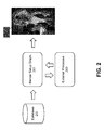
- FIG. 2 illustrates the operation of an exemplary render setup graph 201 that can be used to configure and manage lighting configuration data as well as external processes used to render the computer-generated image 207 of FIG. 1 .
- Render setup graph 201 may receive data, such as animation objects, object configuration data, and the like from database 203, which may include a centralized or decentralized computer-storage database made up of one or more local and/or remote computer-storage databases that can be accessed by one or more users. Using a centralized storage may improve storage efficiency and help ensure that the rendering of a computer-generated animation is performed using a common version of the computer-generated objects.
- the object data received from the database 203 may include data in any format that represents the set of objects (e.g., characters, plants, buildings, etc.) that may be used to render an image.
- the object data may include surface and/or volumetric representations of the objects, identification of parts that make up the objects, and the like.
- the set of objects may include objects that are to be displayed within an image as well as those contained in the database that are not displayed within the image.
- the object configuration data may include visual properties, such as materials, textures, and the like that may be associated with the surfaces of the parts of the objects.
- the object configuration data may also include any number of "looks" that have been defined for the object.
- the looks may include specific configurations of visual properties that have been assigned to the surfaces of the object.
- a chair object may have a first look that assigns a pine wood material to each piece of the chair and a second look that assigns a maple wood material to each piece of the chair. Any number of looks may be defined for each object and may be included within the object configuration data provided by the database 203.
- the data provided by database 203 may include a set of configured computer-generated objects, where each member of the set represents an object configured to have a particular look.
- Render setup graph 201 may include a dependency graph having nodes interconnected by edges along which objects and object configuration data may be passed between nodes.
- the nodes may be used to provide a source of objects and object configuration data, configure visual effects of an object, partition a set of objects, call external processes 205, perform data routing functions within the graph, and the like.
- Render setup graph 201 may provide object data, object configuration data, and any other required data to external processes 205.
- the results of external processes 205 may be returned to render setup graph 201.
- the evaluation of render setup graph 201 and the execution of associated external processes 205 may produce a computer-generated image 207 like that shown in FIG. 1 .
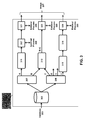
- FIG. 3 illustrates a more detailed view of a visual representation of an exemplary render setup graph 301, which is an example graph that may be used as render setup graph 201 in FIG. 2 .
- render setup graph 301 may receive objects and object configuration data as input from a database (e.g., database 203) and may call external processes 305 to produce a computer-generated image (e.g., image 207).
- a database e.g., database 203
- render setup graph 301 may be displayed on a computer display and manipulated using a graphical user interface and computer I/O hardware.
- render setup graph 301 may be generally configurable by an animator, lighter, or other user and may be used to configure and manage lighting configuration data as well as external processes used to render a computer-generated image.
- render setup graph 301 may include a dependency graph having one or more nodes (e.g., nodes 303, 307, 309, 311, 313, 315, 317, 319, 321, 323, and 325) interconnected by edges.
- the nodes may perform various functions depending on the node type. For example, nodes may represent a source of data, configure visual effects of an object, partition a set of objects, call external processes, perform data routing functions within the graph, and the like.
- the data output by a node may be conveyed to downstream nodes along edges connecting the nodes.
- Render setup graph 301 may include various types of nodes to perform any desired function.
- One example node type that may be included within render setup graph 301 is an object source node (e.g., node 303) representative of a set of configured computer-generated objects (e.g., objects and their associated object configuration data) that are to be used by render setup graph 301 and that may be provided by a local or remote database similar or identical to database 203, discussed above.
- the set of configured computer-generated objects represented by the source node can be assigned by the user. For example, to render a particular image, the user may select a render setup graph 301 and a set of objects to be operated on using the render setup graph 301. In this way, the render setup graph 301 is not constrained to a particular set of objects and can be used to render any desired image.
- the object source node may include reference information that identifies the objects to be used by render setup graph 301.
- the objects may be referenced by an identification of a storage location containing those objects.
- the object source node may include a reference to one or more local or remote databases (e.g., database 203) that contain the objects to be used by render setup graph 301.
- the objects to be used by render setup graph 301 may be added, deleted, or modified at the source database(s) and may be used by the render setup graph 301 without having to modify render setup graph 301 to specifically reference the newly added or modified objects.
- the object source node may include unique identifiers that individually reference the objects to be used by render setup graph 301.
- the object source node may include a list of object names or unique identifiers to define the set of objects to be used by render setup graph 301.
- the object source node may output the set of referenced objects (and associated object configuration data) along one or more edges to one or more connected nodes.
- object source node 303 may provide the set of objects and associated object configuration data contained in database 203 to nodes 307 and 309.
- an organizer node e.g., nodes 307 and 309
- the organizer node may be configured to partition received objects based on any one or more attributes of the objects or associated configuration data, such as object name, object type, geometry name, part name, material, proximity characteristics (e.g., objects within camera frustum, distance from object/camera, existence within a region, or the like) with a time-based limitation (e.g., a time value or range that the position of the object is evaluated), screen projection with a time-based limitation (e.g., a time value or range that the position of the object is evaluated), or the like.
- a time-based limitation e.g., a time value or range that the position of the object is evaluated
- an organizer node may include partition criterion to partition all objects (and associated object configuration data) having an object type of "chair.”
- the organizer node may evaluate metadata associated with the set of objects received at the input of the organizer node and may generate a subset of objects containing all chair-type objects that were received by the organizer node.
- the organizer node may be configured such that the time-based criterion is met if the criterion is met for the entire time range or if the criterion is met at any time within the range.
- the organizer node may generate two outputs for each partition criterion defined for that node.
- the first output may include the subset of objects (which may include zero, some, or all of the received set of objects) that satisfy the partition criterion, while the second output may include the subset of objects that do not satisfy the partition criterion.
- organizer node 307 is coupled to receive the set of objects contained in database 203 from object source node 303.
- Organizer node 307 may be configured to include one partition criterion to partition all objects (and associated object configuration data) having an object type of "chair.” Thus, organizer node 307 may evaluate metadata associated with the set of objects received at the input of organizer node 307 and output the set of chair-type objects at output A. Organizer node 307 may further output the set of remaining objects (e.g., non-chair objects) and associated object configuration data at output B.
- remaining objects e.g., non-chair objects
- organizer node 307 is shown having two outputs, it should be appreciated that organizer nodes may include additional outputs for any additional partition criteria specified for that node.
- the partition criteria may be hierarchical, meaning that one partition criterion may be used to partition the result of another partition criterion.
- organizer node 309 may be configured to include one partition criterion to partition objects having an object type of "plant" and a second partition criterion to partition plants located within a defined region of a scene.
- organizer node 309 may output all plant objects (and associated configuration data) received at the input of organizer node 309 at output C, all non-plant objects (and associated object configuration data) at output D, all plant objects (and associated object configuration data) located within the defined region of the scene at output E, and all plant objects (and associated object configuration data) that are not located within the defined region of the scene at output F.
- Each of the outputs of organizer nodes 307 and 309 may be connected to any number of downstream nodes by edges and may pass their respective subsets of objects (and associated object configuration data) along these edges.
- Partitioning objects based on object attributes and object configuration data advantageously allows an animator, lighter, or other user to select objects having a desired characteristic, without requiring the user to individually identify the selected objects. This obviates the need to modify the render setup graph 301 when the objects in the set of input objects are modified, added, or deleted. For example, if an additional chair object is added to the scene, the organizer node 307 may identify this newly added chair object and output it along with the previously defined chair objects at output A without any additional input from the user.
- merge node 313 may be used to output the aggregate of all inputs received by the merge node.
- merge node 313 may receive output B from organizer node 307 and output C from organizer node 309.
- Merge node 313 may combine these sets of objects and may output the set of objects that includes all ofB and all of C.
- duplicate objects between the inputs of the merge node may be discarded such that only one of each object exists at the output.
- duplicate objects between the inputs of the merge node may not be discarded such that the output of the merge node may include multiple instances of the same object.
- a look selector node that may be used to select a particular "look" for an object.
- the object configuration data passed between nodes may include looks that were defined for the associated object.
- a chair object may have a first look that assigns a pine wood appearance to each piece of the chair and a second look that assigns a maple wood appearance to each piece of the chair.
- the look selector node may be used to select a look for the one or more objects received by the node and may output the one or more objects configured to have the selected look.
- node 311 may be a look selector node and may be configured to select a high-quality look for the objects received from output A of organizer node 307. This may be used, for example, because the objects received from output A of organizer node 307 appear in the foreground of the scene, and thus should appear with a higher level of detail. Look selector node 311 may then output the objects received from output A of organizer node 307 with the high-quality look selected.
- node that may be included within render setup graph 301 is a light node that may be assigned to illuminate one or more objects and which may be configured such that some other set of objects casts shadows due to that light.
- the light node may correspond to one or more light sources, such as ambient light sources, point light sources, spotlights, and the like.
- the light node may be configured to cast shadows by the object(s) received as its input.
- a light can also be assigned to illuminate one or more objects. These shadow casting objects may then cast shadows within a scene when these assigned light sources fall on them.
- node 315 may be a light node configured to cast a shadow due to a point light source falling on the objects received from output F of organizer node 309.
- the objects received from output F of the organizer node 309 may cast shadows from the point light source associated with node 315 when the objects are rendered.
- an organizer node may be used.
- the light source may be associated with the organizer node and may be assigned to illuminate the objects of one or more of the outputs of the organizer node.
- a material node that may be used to assign a material to an object.
- the material node may assign a material to the surface of an entire object or only a portion of the object.
- a material node may be used to assign a material type of brass to a doorknob of a door or may be used to assign a material type of oak to an entire chair.
- the material nodes may simply represent a material and may be linked to an organizer node.
- the organizer node may be further configured to assign the material associated with the linked material node to one or more of the outputs of the organizer node.
- map node that may be used with light and material nodes.
- the map node may specify a texture to be used by the light or material, but is not directly assigned as part of the configuration. Instead, the texture is applied to the light or material by virtue of the map node being linked with the node associated with the light or material.
- node that may be included within render setup graph 301 is a generic node that may be used to encapsulate a process that has not been predefined. These nodes may be associated with a command manually entered by the user to provide flexibility to the graph by allowing users to perform functions that were not explicitly provided by the graph.
- pass node e.g., 317, 321, 323, and 325
- Pass nodes may include an instruction to perform an external process using objects and object configuration data received by the pass node.
- the pass nodes may include a reference to the external processes to be performed and may pass the data received by the pass node to the external process.
- the pass node may receive the output of the external process after the process is executed, and may, in turn, output that result to other nodes within the render setup graph 301 or may output the result of the external process as an output of the render setup graph 301.
- node 317 may be a translucency pass node configured to call an external translucency process 305.
- node 317 may pass the objects (and associated object configuration data) to the external translucency process 305 and may receive the result of the execution of that process.
- Node 317 may then output the result of the external translucency process 305 to another pass node 321 within render setup graph 301.
- This pass node 321 may be, for example, a shade pass node configured to call an external shading process 305.
- node 321 may pass the output of the translucency pass node 317 to the external shading process 305 and may receive the result of the execution of that process.
- the result of the shading process 305 may then be output by the render setup graph 301 as part of image 207.
- the outputs of pass nodes 323 and 325 may call their respective external processes 205 and may output by the render setup graph 301 as part of image 207.
- render setup graph 301 may include other types of nodes, such as splitter nodes, other routing nodes, for-loop nodes, group nodes (representing two or more nodes to avoid screen clutter), and the like. These other nodes can be combined with those discussed above to allow an animator, lighter, or other user to configure, document, and visualize the processes to be performed and the dependencies of these processes on other processes and configuration data.
- a render setup graph may include additional or fewer nodes arranged in any configuration as appropriate to generate a desired image or animation.
- Using a render setup graph similar or identical to that described above advantageously allows the animator or lighter to abstractly define the objects to be used, configure visual effects of these objects (e.g., lighting effects), quickly identify dirty data that should be updated, and define the flow of processes to be performed in a manner that is independent of the objects being input into the graph.
- the render setup graph provides the animator, lighter, or other user with the ability to define and configure rendering passes without having to work on the entire scene.
- the render setup graph may also allow the animator, lighter, or other user to work with a simplified version of the scene that may omit resource intensive visual effects that are used in the final production rendering pass.
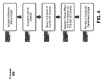
- FIG. 4 illustrates an exemplary process 400 for rendering an image using a render setup graph similar or identical to graph 301, discussed above.
- a render setup graph may be accessed.
- a processor may access a local or remote database containing a render setup graph (e.g., a graph similar or identical to render setup graph 201 or 301) that was generated to render a particular image or animation.
- the render setup graph may include nodes interconnected by edges that define the objects to be used in the rendering process, the configurations for the visual effects of those objects, and the external processes to be executed on those objects.
- a set of animation objects may be accessed.
- Object configuration data that are associated with the objects, such as the visual properties and looks for an object, may also be accessed.
- the set of objects may be defined by the user. For example, to render a particular image, the user may select the render setup graph to be accessed at block 402 and a set of objects to be operated on using that render setup graph. In this way, the render setup graph is not constrained to a particular set of objects and can be used to render any desired image.
- the user-selected objects may be accessed from a database similar or identical to database 203 and provided to the render setup graph at one or more object source nodes similar or identical to object source node 303.
- the set of objects may be defined by the render setup graph.
- the render setup graph may define the objects to be accessed using an object source node similar or identical to object source node 303 discussed above.
- the object source node may include one or more references that define the set of objects abstractly, for example, by identifying one or more storage locations of the objects. In this way, objects to be used by the render setup graph may be modified, added, or deleted without having to modify the render setup graph.
- the object source node may include one or more references that explicitly define the objects to be used by individually identifying the objects (e.g., by using a unique identifier).
- a processor may access the objects by querying a local or remote database using the object identifiers or the location identifiers. For example, if render setup graph 301 was accessed at block 402, the set of objects and associated object configuration data to be accessed at block 404 may be defined by object source node 303. In some examples, object source node 303 may define the set of objects to be used by render setup graph 301 abstractly by identifying database 203 as the source of the objects. Thus, at block 404, the objects and associated object configuration data may be accessed from database 203.
- a subset of the set of objects accessed at block 404 may be selected based on the render setup graph.
- organizer nodes similar or identical to organizer nodes 307 and 309 may be used to selectively partition subsets of objects based on any one or more attributes of the objects or associated configuration data, such as object name, object type, geometry name, part name, material, proximity characteristics (e.g., objects within camera frustum, distance from object/camera, existence within a region, or the like) with a time-based limitation, screen projection with a time-based limitation, or the like.
- render setup graph 301 may include organizer node 307 to define a subset of objects received by object source node 303 by partitioning objects having an object type of "chair.” As a result, a subset of objects containing chair-type objects may be output at output A of organizer node 307.
- visual effects of subsets of the set of objects selected at block 406 may be selected based on the render setup graph.
- the visual effects may include any type of visual effect, such as a look, associated light source, texture, material, or the like.
- Nodes, such as light nodes, material nodes, look selector nodes, and map nodes may be used to select visual effects (e.g., light sources, material properties, looks, and textures) that are to be associated with the subsets of objects.
- a set of objects received by one of the light nodes, material nodes, look selector nodes, map nodes, and the like may be assigned a visual effect as defined by that node.
- the light nodes and material nodes may simply be represent a light source or material, respectively, and may be linked to an organizer node.
- the organizer nodes may be further configured to assign materials or light sources associated with linked nodes to the objects. As a result, any subsequent process performed on those objects may be performed using the selected visual effect(s).
- render setup graph 301 may include organizer node 307 that outputs the subset of objects containing chair-type objects at output A of organizer node 307.
- This subset of chair-type objects may be received by node 311, which may be a look selector node configured to select a high-quality look for the objects received at the input of the node.
- node 311 may be a look selector node configured to select a high-quality look for the objects received at the input of the node.
- all processes performed on the chair-type objects output by look selector node 311 may be performed using the high-quality look (assuming that there are no intervening look selector nodes that may change the selected look).
- a computer-generated image may be rendered based on the render setup graph.
- Rendering the image may include performing one or more external processes on the subset of objects using the selected visual effect(s) based on the render setup graph.
- the external processes may include any process, such as rendering, shading, rasterizing, shadowing calculation, reflection calculation, transmission calculation, or the like that the animator, lighter, or other user may want to perform on the objects used by the render setup graph.
- the render setup graph may include pass nodes similar or identical to pass nodes 317, 321, 323, and 325 that may include references to the external processes to be performed.
- a processor may execute the processes referenced by these pass nodes using the objects and associated configuration data received by these pass nodes.
- a processor may then aggregate the outputs of some or all of the pass nodes to produce a computer-generated image of a scene.
- render setup graph 301 may reference an external translucency process using pass node 317.
- the referenced translucency process may be performed on the subset of chair-type objects partitioned by organizer node 307 using the high-quality look selected based on look selector node 311.
- Render setup graph 301 further includes a pass node 321, which may reference an external shading process.
- the referenced shading process may be performed on the result of the translucency process performed on the subset of chair-type objects using a high-quality look.
- the result may be a high-quality shaded representation of the subset of chair-type objects partitioned by organizer node 307.
- This data may be combined with the outputs of pass nodes 323 and 325, which may output a representation of a character in the scene and the background of the scene, respectively.
- the processor may combine these outputs to render an image of shaded chairs, a character, and a background.
- FIG. 5 illustrates an exemplary process 500 that may be used to generate a render setup graph according to various embodiments.
- a user interface for generating or modifying a render setup graph may be caused to be displayed.
- a processor may cause a user interface similar or identical to interfaces 600 and 700 shown in FIGs. 6 and 7 , respectively, to be displayed on a monitor or other display device.
- the user interface 600/700 may include a first portion 601/701 for displaying a visual representation of the nodes and edges of the render setup graph.
- the user interface may further include a second portion 603/703 having visual representations of one or more node types that may be included within the first portion 601/701 of the display.
- the visual representations of the node types may include text and/or graphics representing the various node types, such as organizer nodes, pass nodes, merge nodes, light nodes, material nodes, map nodes, look selector nodes, object source nodes, generic nodes, or the like.
- the user interface may include any known means for selecting an object, such as a pull-down menu, drag-and-drop icons, or the like.
- a selection of a node type may be received.
- the selection may include an identification of the selected node type.
- the selection may be received by a processor in response to a selection made by a user in the user interface provided at block 502.
- the selection may be made using any known means for selecting an object, such as a pull-down menu, drag-and-drop icons, or the like.
- a selection of a destination of the node type selected at block 504 may be received.
- the destination may include a position within the first portion 601/701 of the display at which the selected node type should be displayed. The user may make this selection using any known selection means, such as clicking on the destination after selecting the node type, dragging the selected node type to the destination, entering coordinates of the destination, or the like.
- a processor may receive the selected destination and may cause a visual representation of the selected node type to be displayed at a position within the user interface corresponding to the selected destination.
- connections for the selected node type may be received.
- the connections may indicate one or more sources of an input to the selected node type or one or more destinations for an output of the selected node type.
- the connections may be selected by a user by selecting an output of one node and an input of another node.
- a display of a visual representation of the node type selected at block 504 may be displayed at a position in the display corresponding to the destination selected at block 506 and with connections received at block 508.
- a processor may cause a visual representation of a node connected by lines to one or more other nodes within the first portion 601/701 of the user interface 600/700 shown in FIGs. 6 and 7 .
- the render setup graph may also be stored for subsequent use to render an image using process 400, described above.
- FIG. 8 illustrates an exemplary animation system 800 that can be used to implement the render setup graph discussed above.
- the render setup graph can be implemented, for example, in either hardware or in software stored on a non-transitory computer-readable storage medium.
- the system can be configured to generate, modify, and evaluate the render setup graph to configure and manage lighting configuration data as well as external processes used to render a computer-generated image.
- the system can be further configured to receive input from a user and to display graphics, an image, or scene of an animation based on the render setup graph.
- the animation system 800 can be configured to receive user input from an input device 820.
- the input device 820 can be any device that receives input from the user and transmits it to the animation system 800.
- the input device 820 can be a keyboard, a mouse, a tablet, a stylus, or the like. Those skilled in the art will recognize that other types of input devices can also be used.
- the animation system 800 can be configured to output graphics, images, or animation to a display device 830.
- the display device 830 can include any device that receives data from the animation system and presents the data to the user.
- the display device may include a liquid crystal display, a set of light-emitting diodes, a projector, or the like. Those skilled in the art will recognize that other types of output devices can also be used.
- the animation system 800 may further include a central processing unit 802.
- the central processing unit may include one or more processing cores.
- the central processing unit 802 may be coupled to and able to communicate with the input device 820.
- the animation system 800 may include multiple processing units.
- the animation system 800 may also include a graphics processing unit 804.
- the graphics processing unit 804 may be dedicated to processing graphics-related data.
- the graphics processing unit 804 may include a single processing core or multiple processing cores.
- the animation system 800 is illustrated with one graphics processing unit 804, the animation system 800 may include a plurality of graphics processing units.
- the central processing unit 802 and/or the graphics processing unit 804 may be coupled to and able to communicate data to the output device 830.
- the animation system 800 may include one or more processors and instructions stored in a non-transitory computer-readable storage medium, such as a memory or storage device, that when executed by the one or more processors, perform animation rendering using a render setup graph, as described above.
- a non-transitory computer-readable storage medium can be any medium that can contain or store the program for use by or in connection with the instruction execution system, apparatus, or device.
- the non-transitory computer-readable storage medium can include, but is not limited to, an electronic, magnetic, optical, electromagnetic, infrared, or semiconductor system, apparatus- or device, a portable computer diskette (magnetic), a random access memory (RAM) (magnetic), a read-only memory (ROM) (magnetic), an erasable programmable read-only memory (EPROM) (magnetic), a portable optical disc such a CD, CD-R, CD-RW, DVD, DVD-R, or DVD-RW, or flash memory such as compact flash cards, secured digital cards, USB memory devices, memory sticks, and the like.
- the animation system 800 may include volatile memory 806, which is a non-transitory computer-readable storage medium, in communication with the central processing unit 802.
- the volatile memory 806 may include, for example, random access memory, such as dynamic random access memory or static random access memory, or any other type of volatile memory.
- the volatile memory 806 may be used to store data or instructions during the operation of the animation system 800. Those skilled in the art will recognize that other types of volatile memory can also be used.
- the animation system 800 may also include non-volatile memory 808, which is a non-transitory computer-readable storage medium, in communication with the central processing unit 802.
- the non-volatile memory 808 may include flash memory, hard disks, magnetic storage devices, read-only memory, or the like.
- the non-volatile memory 808 may be used to store animation data, render setup graph data, computer instructions, or any other information. Those skilled in the art will recognize that other types of non-volatile memory can also be used.
- the animation system 800 is not limited to the devices, configurations, and functionalities described above.
- a single volatile memory 806, non-volatile memory 808, central processing unit 802, graphics processing unit 804, input device 820, and output device 830 are illustrated, a plurality of any of these devices can be implemented internal or external to the animation system 800.
- the animation system 800 may include a network access device for accessing information on a network, such as an internal network or the Internet. Those skilled in the art will recognize that other configurations of the animation system 800 can be used.
- Embodiments of the computer-implemented method, computer-readable storage medium, and apparatus are set out in the following items:
Landscapes
- Engineering & Computer Science (AREA)
- Physics & Mathematics (AREA)
- General Physics & Mathematics (AREA)
- Theoretical Computer Science (AREA)
- Computer Graphics (AREA)
- Computer Hardware Design (AREA)
- General Engineering & Computer Science (AREA)
- Software Systems (AREA)
- Processing Or Creating Images (AREA)
- Image Generation (AREA)
Applications Claiming Priority (1)
| Application Number | Priority Date | Filing Date | Title |
|---|---|---|---|
| US13/844,363 US9589382B2 (en) | 2013-03-15 | 2013-03-15 | Render setup graph |
Publications (2)
| Publication Number | Publication Date |
|---|---|
| EP2779103A2 true EP2779103A2 (de) | 2014-09-17 |
| EP2779103A3 EP2779103A3 (de) | 2015-12-16 |
Family
ID=50382220
Family Applications (1)
| Application Number | Title | Priority Date | Filing Date |
|---|---|---|---|
| EP14159918.3A Withdrawn EP2779103A3 (de) | 2013-03-15 | 2014-03-14 | Wiedergabeeinrichtungsgrafik |
Country Status (3)
| Country | Link |
|---|---|
| US (1) | US9589382B2 (de) |
| EP (1) | EP2779103A3 (de) |
| CN (1) | CN104050701B (de) |
Families Citing this family (7)
| Publication number | Priority date | Publication date | Assignee | Title |
|---|---|---|---|---|
| US10462499B2 (en) * | 2012-10-31 | 2019-10-29 | Outward, Inc. | Rendering a modeled scene |
| EP2915038A4 (de) | 2012-10-31 | 2016-06-29 | Outward Inc | Lieferung von virtualisierten inhalten |
| US20140354658A1 (en) * | 2013-05-31 | 2014-12-04 | Microsoft Corporation | Shader Function Linking Graph |
| CN105224536A (zh) * | 2014-05-29 | 2016-01-06 | 国际商业机器公司 | 划分数据库的方法和装置 |
| US11087430B2 (en) | 2018-09-28 | 2021-08-10 | Apple Inc. | Customizable render pipelines using render graphs |
| US10825258B1 (en) * | 2018-09-28 | 2020-11-03 | Facebook, Inc. | Systems and methods for graph-based design of augmented-reality effects |
| CN113709573B (zh) * | 2020-05-21 | 2023-10-24 | 抖音视界有限公司 | 配置视频特效方法、装置、设备及存储介质 |
Family Cites Families (120)
| Publication number | Priority date | Publication date | Assignee | Title |
|---|---|---|---|---|
| US4922413A (en) * | 1987-03-24 | 1990-05-01 | Center For Innovative Technology | Method for concurrent execution of primitive operations by dynamically assigning operations based upon computational marked graph and availability of data |
| JPH04181423A (ja) | 1990-11-16 | 1992-06-29 | Fujitsu Ltd | バージョン管理方式 |
| US5307295A (en) | 1991-01-14 | 1994-04-26 | Vari-Lite, Inc. | Creating and controlling lighting designs |
| DE69232403T2 (de) | 1991-08-06 | 2002-08-22 | Canon K.K., Tokio/Tokyo | Dreidimensionales Modellverarbeitungsverfahren und -gerät |
| GB2264603B (en) | 1992-02-28 | 1995-08-23 | Sony Broadcast & Communication | Multiplexing and demultiplexing image data |
| US5675752A (en) | 1994-09-15 | 1997-10-07 | Sony Corporation | Interactive applications generator for an interactive presentation environment |
| US5986667A (en) * | 1994-12-22 | 1999-11-16 | Apple Computer, Inc. | Mechanism for rendering scenes using an object drawing subsystem |
| US5692184A (en) | 1995-05-09 | 1997-11-25 | Intergraph Corporation | Object relationship management system |
| US5870097A (en) | 1995-08-04 | 1999-02-09 | Microsoft Corporation | Method and system for improving shadowing in a graphics rendering system |
| US5808617A (en) | 1995-08-04 | 1998-09-15 | Microsoft Corporation | Method and system for depth complexity reduction in a graphics rendering system |
| US5808625A (en) * | 1995-08-04 | 1998-09-15 | Silicon Graphics Incorporated | System and method for using dependency graphs for the control of a graphics creation process |
| US5982389A (en) * | 1996-06-17 | 1999-11-09 | Microsoft Corporation | Generating optimized motion transitions for computer animated objects |
| US5896139A (en) | 1996-08-01 | 1999-04-20 | Platinum Technology Ip, Inc. | System and method for optimizing a scene graph for optimizing rendering performance |
| US7920143B1 (en) | 1997-03-27 | 2011-04-05 | At&T Intellectual Property Ii, L.P. | Method for defining animation parameters for an animation definition interface |
| US6496190B1 (en) | 1997-07-02 | 2002-12-17 | Mental Images Gmbh & Co Kg. | System and method for generating and using systems of cooperating and encapsulated shaders and shader DAGs for use in a computer graphics system |
| US7548238B2 (en) | 1997-07-02 | 2009-06-16 | Nvidia Corporation | Computer graphics shader systems and methods |
| US6154215A (en) * | 1997-08-01 | 2000-11-28 | Silicon Graphics, Inc. | Method and apparatus for maintaining multiple representations of a same scene in computer generated graphics |
| AU761202B2 (en) | 1997-09-22 | 2003-05-29 | Sony Corporation | Generation of a bit stream containing binary image/audio data that is multiplexed with a code defining an object in ascii format |
| US6263496B1 (en) | 1998-02-03 | 2001-07-17 | Amazing Media, Inc. | Self modifying scene graph |
| US6272650B1 (en) | 1998-02-03 | 2001-08-07 | Amazing Media, Inc. | System and method for disambiguating scene graph loads |
| US6243856B1 (en) * | 1998-02-03 | 2001-06-05 | Amazing Media, Inc. | System and method for encoding a scene graph |
| US6263103B1 (en) | 1998-11-30 | 2001-07-17 | Mitsubishi Electric Research Laboratories, Inc. | Estimating scenes using statistical properties of images and scenes |
| US6563504B1 (en) | 1998-12-24 | 2003-05-13 | B3D, Inc. | System and method for creating 3D animated content for multiple playback platforms from a single production process |
| US6362822B1 (en) | 1999-03-12 | 2002-03-26 | Terminal Reality, Inc. | Lighting and shadowing methods and arrangements for use in computer graphic simulations |
| US6760485B1 (en) | 1999-05-20 | 2004-07-06 | Eastman Kodak Company | Nonlinearly modifying a rendered digital image |
| US7657330B2 (en) | 1999-06-11 | 2010-02-02 | Parker-Hannifin Corporation | Optical ring architecture |
| US6556200B1 (en) | 1999-09-01 | 2003-04-29 | Mitsubishi Electric Research Laboratories, Inc. | Temporal and spatial coherent ray tracing for rendering scenes with sampled and geometry data |
| US7184038B2 (en) | 1999-09-24 | 2007-02-27 | Sun Microsystems, Inc. | Using render bin parallelism for rendering scene graph based graphics data |
| US7231327B1 (en) | 1999-12-03 | 2007-06-12 | Digital Sandbox | Method and apparatus for risk management |
| US7133041B2 (en) | 2000-02-25 | 2006-11-07 | The Research Foundation Of State University Of New York | Apparatus and method for volume processing and rendering |
| US7414626B1 (en) | 2000-05-30 | 2008-08-19 | Autodesk, Inc. | System for passing algorithms with polymorphic parameter sets in a dependency graph of a graphic creation process |
| US7659894B2 (en) | 2000-06-19 | 2010-02-09 | Mental Images Gmbh | Terminating spatial partition hierarchies by a priori bounding memory |
| US7865306B2 (en) | 2000-09-28 | 2011-01-04 | Michael Mays | Devices, methods, and systems for managing route-related information |
| US7176921B2 (en) | 2000-10-20 | 2007-02-13 | Sony Corporation | Graphical rewriting system for multimedia descriptions |
| US6845358B2 (en) | 2001-01-05 | 2005-01-18 | Matsushita Electric Industrial Co., Ltd. | Prosody template matching for text-to-speech systems |
| EP1223759A1 (de) | 2001-01-08 | 2002-07-17 | Robert Bosch Gmbh | Verfahren zur Erzeugung eines Erweiterungscodes für die binarische Beschreibung von Multimediadaten |
| US6873344B2 (en) | 2001-02-22 | 2005-03-29 | Sony Corporation | Media production system using flowgraph representation of operations |
| EP1391848A4 (de) | 2001-05-14 | 2009-11-04 | Netdimension Corp | Informationsverteilungssystem und informationsverteilungsverfahren |
| US7117216B2 (en) | 2001-06-07 | 2006-10-03 | Sun Microsystems, Inc. | Method and apparatus for runtime merging of hierarchical trees |
| US6919891B2 (en) | 2001-10-18 | 2005-07-19 | Microsoft Corporation | Generic parameterization for a scene graph |
| JP4075039B2 (ja) | 2002-02-19 | 2008-04-16 | 株式会社セガ | テクスチャマッピング方法、プログラム及び装置 |
| US7439982B2 (en) | 2002-05-31 | 2008-10-21 | Envivio, Inc. | Optimized scene graph change-based mixed media rendering |
| US7129943B2 (en) | 2002-11-15 | 2006-10-31 | Microsoft Corporation | System and method for feature-based light field morphing and texture transfer |
| KR100443552B1 (ko) | 2002-11-18 | 2004-08-09 | 한국전자통신연구원 | 가상 현실 구현 시스템 및 방법 |
| US7034835B2 (en) * | 2002-11-29 | 2006-04-25 | Research In Motion Ltd. | System and method of converting frame-based animations into interpolator-based animations |
| US20050140672A1 (en) | 2003-02-18 | 2005-06-30 | Jeremy Hubbell | Shader editor and compiler |
| US7417645B2 (en) | 2003-03-27 | 2008-08-26 | Microsoft Corporation | Markup language and object model for vector graphics |
| US7126606B2 (en) * | 2003-03-27 | 2006-10-24 | Microsoft Corporation | Visual and scene graph interfaces |
| US7173623B2 (en) * | 2003-05-09 | 2007-02-06 | Microsoft Corporation | System supporting animation of graphical display elements through animation object instances |
| US7444595B2 (en) | 2003-08-13 | 2008-10-28 | National Instruments Corporation | Graphical programming system and method for creating and managing a scene graph |
| US7511718B2 (en) * | 2003-10-23 | 2009-03-31 | Microsoft Corporation | Media integration layer |
| US7432925B2 (en) * | 2003-11-21 | 2008-10-07 | International Business Machines Corporation | Techniques for representing 3D scenes using fixed point data |
| JP2005284694A (ja) | 2004-03-30 | 2005-10-13 | Fujitsu Ltd | 3次元モデルデータ提供プログラム、3次元モデルデータ提供サーバ、及び3次元モデルデータ転送方法 |
| US7231632B2 (en) | 2004-04-16 | 2007-06-12 | Apple Computer, Inc. | System for reducing the number of programs necessary to render an image |
| US7248265B2 (en) | 2004-04-16 | 2007-07-24 | Apple Inc. | System and method for processing graphics operations with graphics processing unit |
| US7330185B2 (en) | 2004-05-10 | 2008-02-12 | Pixar | Techniques for processing complex scenes |
| US7821516B2 (en) | 2004-05-17 | 2010-10-26 | Pixar | Automatic pre-render pinning of change isolated assets methods and apparatus |
| US7614037B2 (en) | 2004-05-21 | 2009-11-03 | Microsoft Corporation | Method and system for graph analysis and synchronization |
| CN101233504B (zh) | 2005-01-05 | 2010-11-10 | 希尔克瑞斯特实验室公司 | 用于用户界面的分布式软件架构 |
| WO2006094199A2 (en) | 2005-03-03 | 2006-09-08 | Pixar | Hybrid hardware-accelerated relighting system for computer cinematography |
| US20060274070A1 (en) | 2005-04-19 | 2006-12-07 | Herman Daniel L | Techniques and workflows for computer graphics animation system |
| EP1918880A3 (de) | 2005-04-19 | 2009-09-02 | Digitalfish, Inc. | Verfahren und Arbeitsabläufe für ein Computergraphiken-Animationssystem |
| JP2009500730A (ja) | 2005-07-01 | 2009-01-08 | メンタル イメージズ ゲーエムベーハー | コンピュータ・グラフィック・シェイダー・システムおよび方法 |
| US7441230B2 (en) | 2005-10-07 | 2008-10-21 | Lucasfilm Entertainment Company Ltd. | Method of utilizing product proxies with a dependency graph |
| WO2007067131A1 (en) | 2005-12-08 | 2007-06-14 | Agency 9 Ab | A method to render a root-less scene graph with a user controlled order of rendering |
| US20070176926A1 (en) | 2006-01-31 | 2007-08-02 | Garcia Jose M D | Lighting states in a computer aided design |
| US8024356B2 (en) | 2006-02-03 | 2011-09-20 | Autodesk, Inc. | Database-managed image processing |
| US8773433B1 (en) | 2006-04-12 | 2014-07-08 | Pixar | Component-based lighting |
| US7836086B2 (en) | 2006-06-09 | 2010-11-16 | Pixar | Layering and referencing of scene description |
| FR2902908B1 (fr) | 2006-06-21 | 2012-12-07 | Streamezzo | Procede de creation et de restitution optimise du rendu d'une scene multimedia comprenant au moins un objet actif, sans modification prealable de la semantique et/ou du format de description de scene |
| WO2008011353A2 (en) | 2006-07-16 | 2008-01-24 | The Jim Henson Company | System and method of producing an animated performance utilizing multiple cameras |
| CA2593902A1 (en) | 2006-07-31 | 2008-01-31 | Avid Technology, Inc. | Efficient processing of operator graphs representing three-dimensional character animation |
| TW200811756A (en) | 2006-08-23 | 2008-03-01 | Shu-Kai Yang | Computer graphics system and method thereof |
| US20080122838A1 (en) | 2006-09-27 | 2008-05-29 | Russell Dean Hoover | Methods and Systems for Referencing a Primitive Located in a Spatial Index and in a Scene Index |
| AU2006235850B2 (en) | 2006-11-03 | 2012-12-20 | Canon Information Systems Research Australia Pty Ltd | Reviewing editing operations |
| WO2008064363A2 (en) | 2006-11-22 | 2008-05-29 | Take Two Interactive Software, Inc. | System and method for real-time pose-based deformation of character models |
| US7782319B2 (en) | 2007-03-28 | 2010-08-24 | Autodesk, Inc. | Three-dimensional orientation indicator and controller |
| US8189003B2 (en) | 2007-05-08 | 2012-05-29 | Dreamworks Animation Llc | System and method for rendering computer graphics utilizing a shadow illuminator |
| US20090021513A1 (en) | 2007-07-18 | 2009-01-22 | Pixblitz Studios Inc. | Method of Customizing 3D Computer-Generated Scenes |
| US20090027380A1 (en) | 2007-07-23 | 2009-01-29 | Vivek Rajan | 3-D visualization |
| US8259110B1 (en) | 2007-11-12 | 2012-09-04 | Adobe Systems Incorporated | Method and apparatus for computing direct lighting for global illumination rendering in 3-D computer graphics |
| US8274506B1 (en) | 2008-04-28 | 2012-09-25 | Adobe Systems Incorporated | System and methods for creating a three-dimensional view of a two-dimensional map |
| US8612485B2 (en) * | 2008-08-11 | 2013-12-17 | Sony Corporation | Deferred 3-D scenegraph processing |
| CA2734332A1 (en) | 2008-09-24 | 2010-04-01 | The Bakery | Method and system for rendering or interactive lighting of a complex three dimensional scene |
| US8441496B1 (en) | 2008-09-30 | 2013-05-14 | Adobe Systems Incorporated | Method and system for modifying and rendering scenes via display lists |
| US8665274B2 (en) | 2008-10-01 | 2014-03-04 | International Business Machines Corporation | Method and system for generating and displaying an interactive dynamic view of bi-directional impact analysis results for multiply connected objects |
| US8442328B2 (en) | 2008-10-03 | 2013-05-14 | 3M Innovative Properties Company | Systems and methods for evaluating robustness of saliency predictions of regions in a scene |
| JP5605571B2 (ja) | 2008-10-07 | 2014-10-15 | 国立大学法人お茶の水女子大学 | 部分グラフ検出装置、部分グラフ検出方法、プログラム、データのデータ構造、及び情報記憶媒体 |
| US8352443B1 (en) | 2008-11-08 | 2013-01-08 | Pixar | Representing scene description in databases |
| US8508537B2 (en) | 2008-11-17 | 2013-08-13 | Disney Enterprises, Inc. | System and method for dependency graph evaluation for animation |
| US8730245B2 (en) | 2008-12-01 | 2014-05-20 | Naturalmotion Ltd. | Defining an animation of a virtual object within a virtual world |
| US8411086B2 (en) | 2009-02-24 | 2013-04-02 | Fuji Xerox Co., Ltd. | Model creation using visual markup languages |
| US8624898B1 (en) | 2009-03-09 | 2014-01-07 | Pixar | Typed dependency graphs |
| US20100289804A1 (en) | 2009-05-13 | 2010-11-18 | International Business Machines Corporation | System, mechanism, and apparatus for a customizable and extensible distributed rendering api |
| US9142044B2 (en) | 2009-05-26 | 2015-09-22 | Oracle International Corporation | Apparatus, systems and methods for layout of scene graphs using node bounding areas |
| EP2443751A1 (de) | 2009-06-17 | 2012-04-25 | Coherent Logix Incorporated | Parallele ausführung von verfahren auf trellis-basis |
| WO2010150150A1 (en) | 2009-06-25 | 2010-12-29 | Koninklijke Philips Electronics N.V. | Effect-driven specification of dynamic lighting |
| US8369564B2 (en) | 2009-06-30 | 2013-02-05 | Apple Inc. | Automatic generation and use of region of interest and domain of definition functions |
| US8352397B2 (en) | 2009-09-10 | 2013-01-08 | Microsoft Corporation | Dependency graph in data-driven model |
| US20110090236A1 (en) | 2009-10-15 | 2011-04-21 | Microsoft Corporation | Graphic Object Data Binding |
| CN102053989A (zh) | 2009-10-30 | 2011-05-11 | 国际商业机器公司 | 用于确定要被物化的节点的方法和系统 |
| US9171390B2 (en) | 2010-01-19 | 2015-10-27 | Disney Enterprises, Inc. | Automatic and semi-automatic generation of image features suggestive of motion for computer-generated images and video |
| US8488783B2 (en) | 2010-02-19 | 2013-07-16 | Nokia | Method and apparatus for applying recipient criteria in identity-based encryption |
| US8665266B2 (en) | 2010-06-23 | 2014-03-04 | The United States Of America, As Represented By The Secretary Of The Navy | Global visualization process terrain database builder |
| US8629875B2 (en) | 2010-11-09 | 2014-01-14 | Qualcomm Incorporated | Constraint systems and methods for manipulating non-hierarchical objects |
| US8892569B2 (en) | 2010-12-23 | 2014-11-18 | Ianywhere Solutions, Inc. | Indexing spatial data with a quadtree index having cost-based query decomposition |
| FR2973907B1 (fr) | 2011-04-11 | 2013-04-26 | Bull Sas | Procede et dispositif de traitement de commandes d'administration dans un cluster |
| US20120280991A1 (en) | 2011-05-03 | 2012-11-08 | Microsoft Corporation | Employing mesh files to animate transitions in client applications |
| US9001128B2 (en) | 2011-05-06 | 2015-04-07 | Danglesnort, Llc | Efficient method of producing an animated sequence of images |
| US9552212B2 (en) | 2011-05-06 | 2017-01-24 | Microsoft Technology Licensing, Llc | Caching intermediate data for scroll view rendering |
| US20130086328A1 (en) | 2011-06-13 | 2013-04-04 | Paneve, Llc | General Purpose Digital Data Processor, Systems and Methods |
| US9508181B2 (en) | 2011-08-31 | 2016-11-29 | Adobe Systems Incorporated | Ordering and rendering buffers for complex scenes with cyclic dependency |
| WO2013036691A1 (en) | 2011-09-06 | 2013-03-14 | Dreamworks Animation Llc | Optimizing graph evaluation |
| US20130063472A1 (en) | 2011-09-08 | 2013-03-14 | Microsoft Corporation | Customized image filters |
| US20130063460A1 (en) | 2011-09-08 | 2013-03-14 | Microsoft Corporation | Visual shader designer |
| US9240073B2 (en) | 2011-11-15 | 2016-01-19 | Pixar | File format for representing a scene |
| GB2500405B (en) | 2012-03-20 | 2014-04-16 | Lightmap Ltd | Point and click lighting for image based lighting surfaces |
| US9892529B2 (en) | 2012-08-03 | 2018-02-13 | Dreamworks Animation L.L.C. | Constraint evaluation in directed acyclic graphs |
| US10110412B2 (en) | 2012-10-17 | 2018-10-23 | Disney Enterprises, Inc. | Dynamically allocated computing method and system for distributed node-based interactive workflows |
| EP2779100A1 (de) | 2013-03-11 | 2014-09-17 | Thomson Licensing | Verfahren zur Verarbeitung einer computeranimierten Szene und zugehörige Vorrichtung |
-
2013
- 2013-03-15 US US13/844,363 patent/US9589382B2/en active Active
-
2014
- 2014-03-14 EP EP14159918.3A patent/EP2779103A3/de not_active Withdrawn
- 2014-03-16 CN CN201410096622.9A patent/CN104050701B/zh active Active
Non-Patent Citations (1)
| Title |
|---|
| NATIONAL INSTRUMENTS: "LabVIEW Function and VI Reference Manual", 1 January 1998 (1998-01-01), pages 1 - 609, XP055640128, Retrieved from the Internet <URL:http://www.ni.com/pdf/manuals/321526b.pdf> [retrieved on 20191107] * |
Also Published As
| Publication number | Publication date |
|---|---|
| CN104050701A (zh) | 2014-09-17 |
| EP2779103A3 (de) | 2015-12-16 |
| CN104050701B (zh) | 2018-10-12 |
| US9589382B2 (en) | 2017-03-07 |
| US20140267309A1 (en) | 2014-09-18 |
Similar Documents
| Publication | Publication Date | Title |
|---|---|---|
| US9589382B2 (en) | Render setup graph | |
| US6570578B1 (en) | System for automatic generation of selective partial renderings of complex scenes | |
| US10372308B2 (en) | Predictive material editor | |
| US9208597B2 (en) | Generalized instancing for three-dimensional scene data | |
| CN105631925A (zh) | 基于osg三维渲染引擎预处理的三维场景生成方法及装置 | |
| CN104050232B (zh) | 计算机生成动画资产的任意分层加标签 | |
| US9514562B2 (en) | Procedural partitioning of a scene | |
| EP2973412B1 (de) | Konservative partitionierung zur darstellung einer computergenerierten animation | |
| EP2779112B1 (de) | Für Knoten in einem Render-Setup-Graph | |
| US9582247B1 (en) | Preserving data correlation in asynchronous collaborative authoring systems | |
| EP2981944B1 (de) | Erscheinungsbildbasierte auswahl zur generierung einer computeranimation | |
| CN110992459B (zh) | 基于分区的室内场景渲染及优化方法 | |
| US9569875B1 (en) | Ordered list management | |
| US9218785B2 (en) | Lighting correction filters | |
| CN120431260A (zh) | 商品显示方法、装置、电子设备及介质 | |
| US20140129608A1 (en) | Distributed production pipeline | |
| Green | An Interface for Real-Time Networked Streaming of 3D Scenes |
Legal Events
| Date | Code | Title | Description |
|---|---|---|---|
| 17P | Request for examination filed |
Effective date: 20140314 |
|
| AK | Designated contracting states |
Kind code of ref document: A2 Designated state(s): AL AT BE BG CH CY CZ DE DK EE ES FI FR GB GR HR HU IE IS IT LI LT LU LV MC MK MT NL NO PL PT RO RS SE SI SK SM TR |
|
| AX | Request for extension of the european patent |
Extension state: BA ME |
|
| PUAI | Public reference made under article 153(3) epc to a published international application that has entered the european phase |
Free format text: ORIGINAL CODE: 0009012 |
|
| PUAL | Search report despatched |
Free format text: ORIGINAL CODE: 0009013 |
|
| AK | Designated contracting states |
Kind code of ref document: A3 Designated state(s): AL AT BE BG CH CY CZ DE DK EE ES FI FR GB GR HR HU IE IS IT LI LT LU LV MC MK MT NL NO PL PT RO RS SE SI SK SM TR |
|
| AX | Request for extension of the european patent |
Extension state: BA ME |
|
| RIC1 | Information provided on ipc code assigned before grant |
Ipc: G06T 15/50 20110101ALI20151106BHEP Ipc: G06T 19/00 20110101ALI20151106BHEP Ipc: G06T 13/20 20110101AFI20151106BHEP |
|
| R17P | Request for examination filed (corrected) |
Effective date: 20160615 |
|
| RBV | Designated contracting states (corrected) |
Designated state(s): AL AT BE BG CH CY CZ DE DK EE ES FI FR GB GR HR HU IE IS IT LI LT LU LV MC MK MT NL NO PL PT RO RS SE SI SK SM TR |
|
| 17Q | First examination report despatched |
Effective date: 20180718 |
|
| STAA | Information on the status of an ep patent application or granted ep patent |
Free format text: STATUS: THE APPLICATION HAS BEEN WITHDRAWN |
|
| 18W | Application withdrawn |
Effective date: 20200211 |