EP2779236A2 - Induktoren mit magnetischem Kern für integrierte Spannungsregler - Google Patents
Induktoren mit magnetischem Kern für integrierte Spannungsregler Download PDFInfo
- Publication number
- EP2779236A2 EP2779236A2 EP20140158260 EP14158260A EP2779236A2 EP 2779236 A2 EP2779236 A2 EP 2779236A2 EP 20140158260 EP20140158260 EP 20140158260 EP 14158260 A EP14158260 A EP 14158260A EP 2779236 A2 EP2779236 A2 EP 2779236A2
- Authority
- EP
- European Patent Office
- Prior art keywords
- die
- slotted
- magnetic
- mci
- layers
- Prior art date
- Legal status (The legal status is an assumption and is not a legal conclusion. Google has not performed a legal analysis and makes no representation as to the accuracy of the status listed.)
- Granted
Links
Images


Classifications
-
- H—ELECTRICITY
- H10—SEMICONDUCTOR DEVICES; ELECTRIC SOLID-STATE DEVICES NOT OTHERWISE PROVIDED FOR
- H10W—GENERIC PACKAGES, INTERCONNECTIONS, CONNECTORS OR OTHER CONSTRUCTIONAL DETAILS OF DEVICES COVERED BY CLASS H10
- H10W42/00—Arrangements for protection of devices
-
- H—ELECTRICITY
- H10—SEMICONDUCTOR DEVICES; ELECTRIC SOLID-STATE DEVICES NOT OTHERWISE PROVIDED FOR
- H10D—INORGANIC ELECTRIC SEMICONDUCTOR DEVICES
- H10D84/00—Integrated devices formed in or on semiconductor substrates that comprise only semiconducting layers, e.g. on Si wafers or on GaAs-on-Si wafers
-
- H—ELECTRICITY
- H01—ELECTRIC ELEMENTS
- H01F—MAGNETS; INDUCTANCES; TRANSFORMERS; SELECTION OF MATERIALS FOR THEIR MAGNETIC PROPERTIES
- H01F17/00—Fixed inductances of the signal type
- H01F17/0006—Printed inductances
-
- H—ELECTRICITY
- H10—SEMICONDUCTOR DEVICES; ELECTRIC SOLID-STATE DEVICES NOT OTHERWISE PROVIDED FOR
- H10D—INORGANIC ELECTRIC SEMICONDUCTOR DEVICES
- H10D1/00—Resistors, capacitors or inductors
- H10D1/20—Inductors
-
- H—ELECTRICITY
- H10—SEMICONDUCTOR DEVICES; ELECTRIC SOLID-STATE DEVICES NOT OTHERWISE PROVIDED FOR
- H10D—INORGANIC ELECTRIC SEMICONDUCTOR DEVICES
- H10D86/00—Integrated devices formed in or on insulating or conducting substrates, e.g. formed in silicon-on-insulator [SOI] substrates or on stainless steel or glass substrates
- H10D86/80—Integrated devices formed in or on insulating or conducting substrates, e.g. formed in silicon-on-insulator [SOI] substrates or on stainless steel or glass substrates characterised by multiple passive components, e.g. resistors, capacitors or inductors
- H10D86/85—Integrated devices formed in or on insulating or conducting substrates, e.g. formed in silicon-on-insulator [SOI] substrates or on stainless steel or glass substrates characterised by multiple passive components, e.g. resistors, capacitors or inductors characterised by only passive components
-
- H—ELECTRICITY
- H10—SEMICONDUCTOR DEVICES; ELECTRIC SOLID-STATE DEVICES NOT OTHERWISE PROVIDED FOR
- H10W—GENERIC PACKAGES, INTERCONNECTIONS, CONNECTORS OR OTHER CONSTRUCTIONAL DETAILS OF DEVICES COVERED BY CLASS H10
- H10W44/00—Electrical arrangements for controlling or matching impedance
-
- H—ELECTRICITY
- H10—SEMICONDUCTOR DEVICES; ELECTRIC SOLID-STATE DEVICES NOT OTHERWISE PROVIDED FOR
- H10W—GENERIC PACKAGES, INTERCONNECTIONS, CONNECTORS OR OTHER CONSTRUCTIONAL DETAILS OF DEVICES COVERED BY CLASS H10
- H10W90/00—Package configurations
-
- H—ELECTRICITY
- H01—ELECTRIC ELEMENTS
- H01F—MAGNETS; INDUCTANCES; TRANSFORMERS; SELECTION OF MATERIALS FOR THEIR MAGNETIC PROPERTIES
- H01F17/00—Fixed inductances of the signal type
- H01F17/0006—Printed inductances
- H01F2017/0066—Printed inductances with a magnetic layer
-
- H—ELECTRICITY
- H10—SEMICONDUCTOR DEVICES; ELECTRIC SOLID-STATE DEVICES NOT OTHERWISE PROVIDED FOR
- H10D—INORGANIC ELECTRIC SEMICONDUCTOR DEVICES
- H10D1/00—Resistors, capacitors or inductors
- H10D1/60—Capacitors
- H10D1/68—Capacitors having no potential barriers
-
- H—ELECTRICITY
- H10—SEMICONDUCTOR DEVICES; ELECTRIC SOLID-STATE DEVICES NOT OTHERWISE PROVIDED FOR
- H10W—GENERIC PACKAGES, INTERCONNECTIONS, CONNECTORS OR OTHER CONSTRUCTIONAL DETAILS OF DEVICES COVERED BY CLASS H10
- H10W90/00—Package configurations
- H10W90/701—Package configurations characterised by the relative positions of pads or connectors relative to package parts
- H10W90/721—Package configurations characterised by the relative positions of pads or connectors relative to package parts of bump connectors
- H10W90/724—Package configurations characterised by the relative positions of pads or connectors relative to package parts of bump connectors between a chip and a stacked insulating package substrate, interposer or RDL
Definitions
- Embodiments of the invention are in the field of semiconductor packages and, in particular, semiconductor packages including magnetic core inductor (MCI) structures for integrated voltage regulators.
- MCI magnetic core inductor
- On-die voltage regulation can be used to locally change the voltage, e.g., within core voltage changes, for active power management. Additionally, On-die voltage regulation can also be designed to automatically maintain a constant voltage level for an associated semiconductor die. In another application, on-die voltage regulation can also be used to throttle voltages in real time if active power management required.
- a voltage regulator may be a simple "feed-forward" design or may include negative feedback control loops. It may use an electromechanical mechanism, or electronic components. Depending on the design, it may be used to regulate one or more AC or DC voltages.
- Inductors may be implemented on substrates such as an integrated circuit die or a printed circuit board (PCB). Such implementations involve placing patterns of material (e.g., a conductive material) on one or more substrate layers. This placement may be through lithographic techniques.
- Inductors used for RF applications are typically air-core spiral inductors or , in some cases, ferrite magnetic inductors.
- air-core spiral inductors typically require a substantial amount of space (area) on a substrate (e.g., an IC die).
- such inductors typically, but not necessarily, couple to a high-resistivity substrate.
- a magnetic layer underneath the stripline effectively shields the substrate at the operating frequency of an associated VR.
- MCI magnetic core inductor
- One or more embodiments described herein are directed to magnetic inductor structures for integrated voltage regulators.
- the structures may be designed to provide a reduced associated on die and/or on package capacitor area and to improve efficiency of the inductors and associated voltage regulators.
- approaches or structures described herein enable use of a reduced capacitance while moving to increased frequency for operation of an associated voltage regulator.
- inductor structures involve slotting aspects, i.e., slotted features. Such slotted features may enable mitigation of rapid inductance value drop by capacitive coupling through proximate thin dielectric layers.
- the magnetic inductors described are magnetic core inductors having a magnetic core made of a ferromagnetic or ferrimagnetic material or alloys, such as iron, ferrite (iron oxide), cobalt or nickel, nickel Iron alloys, cobalt alloys, cobalt iron alloys, Mn alloys and other known soft magnetic materials to increase the inductance.
- MCIs magnetic core inductors
- Air core inductors typically require large form factor semiconductor packages, and possibly cored packages. As scaling and die shrinking is performed with each generation, package scaling is often required to provide ever smaller form factors. However, the reduction in package size makes inclusion of ACIs difficult since a smaller package means a smaller inductor which can lead to increased losses for the ACIs. Nonetheless, power management is trending towards the use of FIVRs without a full understanding of the scalability of FIVR components. In the near future, the processor core area is expected to decrease by approximately 50% with each generation. Unfortunately, ACIs cannot scale by the same factor while maintaining the same performance.
- MCIs may offer comparable performance to ACIs in a much smaller volume through the use of high permeability materials (e.g., magnetic materials).
- high permeability materials e.g., magnetic materials
- conventional MCIs may suffer from magnetic saturation effects.
- MCIs are small but have high magnetic fields (i.e., magnetic flux densities) inside the magnetic material. The small size and high magnetic fields can lead to such magnetic saturation which may cause high ripple currents that significantly reduces the efficiency of the MCI. Such an effect may limit the use of MCIs in many power delivery applications requiring large direct current (DC) and alternating current (AC) currents.
- DC direct current
- AC alternating current
- magnetic saturation effects may lead to one or more detriments, such as, but not limited to, limiting the maximum achievable FIVR efficiency, forcing the use of certain MCI topologies which renders the efficient operating region smaller and significantly increases the complexity of the FIVR control circuitry (FIVR controller) design, and requiring large MIM capacitors at the output.
- detriments such as, but not limited to, limiting the maximum achievable FIVR efficiency, forcing the use of certain MCI topologies which renders the efficient operating region smaller and significantly increases the complexity of the FIVR control circuitry (FIVR controller) design, and requiring large MIM capacitors at the output.
- MIM capacitor capacitance density another factor that limits scaling down the area of FIVR circuits and PMICs is the available metal-insulator-metal (MIM) capacitor capacitance density.
- MIM capacitance density a certain MIM capacitance value is needed to meet the ripple voltage and transient response requirements of associated voltage regulators.
- a scaling approach for MIM capacitors could be based on adding additional MIM capacitor material layers. Such an approach, however, results in significantly increased die cost and potential yield issues if the MIM capacitor capacitance value is to remain constant across scaled technology nodes.
- FIVR and PMICs require both high voltage input (e.g., approximately twice the corresponding gate voltage, Vcc) MIM capacitance and low voltage (Vcc) output MIM capacitance.
- Vcc gate voltage
- Vcc low voltage
- One option to reduce the required MIM capacitor capacitance value is to increase the switching frequency of the voltage regulator.
- standard MCIs cannot typically operate at switching frequencies higher than approximately 100 MHz since the associated inductance drops very quickly relative to increasing frequency in that range. Additionally, increasing the switching frequencies can significantly increase associated transistor switching losses. This stems from a large size of the transistors used in FIVR to support the very high turbo mode currents of present computer processing units (CPUs) that are optimized for desktop and laptop applications.
- the maximum turbo currents can be significantly reduced.
- a reduction in maximum turbo currents can enable use of smaller transistors and, thus, can reduce the switching losses and allow use of high switching frequencies.
- faster compensators can be designed to take advantage of the high switching frequencies and allow extremely fast idle to turbo transitions.
- the high switching frequencies enable the miniaturization of the overall system, including the inductors and the associated MIM capacitors.
- MCI structures are provided that enable MCI inductors to operate at switching frequencies up to 400 MHz (e.g., up to approximately 4x higher than standard MCIs) with reasonable efficiencies.
- significantly smaller MIM capacitors e.g., nearly 1/3 rd the size
- the on-CPU-die MIM capacitor routing can be significantly simplified, and the required overall MIM capacitor area can be further reduced.
- actual measurements verifying the characteristics of the described MCI inductors, and simulation data regarding the efficiency of such inductors in a standard voltage regulator.
- the savings in MIM capacitor area due to splitting the input and output MIM capacitor capacitances is exemplified by placing the MIM capacitors on an associated MCI die.
- Figure 1A illustrates (a) a top angled view of a standard magnetic inductor 100A, (b) a top angled view of a slotted magnetic inductor 100B, in accordance with a first embodiment of the present invention, and (c) a plan view of another slotted magnetic inductor 100C, in accordance with a second embodiment of the present invention.
- a standard magnetic core inductor (MCI) structure is shown as 100A in Figure 1A .
- the standard MCI 100A includes two copper traces 102A and 104A sandwiched between multi-layered (e.g., laminated) magnetic material 106A.
- Inductor terminals are shown as 108A.
- thin magnetic layers e.g., a few hundred nanometers thick
- thin dielectric layers e.g., approximately 25 nm thick
- the capacitive coupling through the thin dielectric layers causes the inductance value to drop rapidly.
- an inductor structure 100B includes two metal traces 102B and 104B sandwiched between multi-layered (e.g., laminated) magnetic material 106B.
- the magnetic material 106B is sectioned, e.g., into four sections in the exemplary embodiment of Figure 1A , part (b).
- the inductor structure 100B is referred to herein as a type of slotted inductor structure.
- the frequency at which the inductance drops increases significantly, as described in greater detail below in association with Figure 2 , part (a).
- the higher threshold frequency may be related to the reduction of the conversion of eddy currents inside the magnetic material along the length of the inductor to displacement current across the dielectric.
- the inductance can be maintained relatively constant up to approximately 1 GHz.
- inductor structure 100C includes metal (e.g., copper) layer 102C and a plurality of magnetic material layers 106C having irregular slotting 110C therein.
- inductor structure 100B has regular slotting in that all magnetic layers are slotted in the same location.
- Figure 1B illustrates a variety of slotting patterns with only partial slots, in accordance with an embodiment of the present invention.
- Figure 1C illustrates a variety of slotting patterns with complete slots, in accordance with an embodiment of the present invention.
- Other possibilities include, but are not limited to, in one or more embodiments, slotting of wings only, slotting of body only, slotting all the way across, or a combination of wing slotting and partial body slotting.
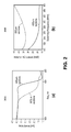
- Figure 2 includes (a) a plot 200A of inductance (in nH) as a function of Frequency (in Hz) for two different inductors, and (b) a plot 200B of inductor AC losses (in mW) as a function of switching frequency (in MHz), in accordance with an embodiment of the present invention.
- the frequecny at which inductance falls off for a given length inductor e.g., an 800 micron inductor
- the inductor AC losses in a buck regulator are shown as a function of the switching frequency.
- Figure 3 is a plot 300 of on die/on package capacitance value (in nF) as a function of switching frequency (in MHz), in accordance with an embodiment of the present invention.
- a minimum output capacitor capacitance for a ripple voltage of less than 10 mV and stable compensator as a function of the switching frequency is provided.
- the calculations were performed using simplified capacitor and compensator models. However, the models show the expected trend of the reduction of the MIM capacitor capacitance with higher switching frequencies.
- the worst case scenarios were used in the simulation (e.g., a compensator for a 16 phase regulator and ripple voltage for a 4 phase regulator). It is to be understood that other efficiency and system design considerations might prevent operation above approximately 250 MHz due to transistor losses.
- a metal-insulator-metal (MIM) capacitor may be integrated, at least on an architectural level, with a slotted inductor structure for use in an FIVR.
- Figure 4 illustrates a plan view of a MIM capacitor structure for use in a FIVR, in accordance with an embodiment of the present invention.
- a MIM capacitor structure includes an input MIM portion and an output MIM portion.
- the switching activity of a corresponding buck regulator and the load transitions of a CPU core can create a large amount of noise.
- the high frequency components of this noise are decoupled using a MIM capacitor, such as the MIM capacitor structure of Figure 4 .
- the two capacitors share a same area. Routing overhead can be very significant and, thus, splitting the capacitors can help reduce the area.
- the MIM capacitor density must increase such that the reduced available area is used to obtain the same amount of total MIM capacitor capacitance.
- Such an increase in MIM capacitor density could be achieved by adding additional layers to a MIM capacitor stack.
- this approach adds process cost and reduces yield in an expensive, leading-edge CPU fabrication process. Increasing the capacitance can require significant increase in the die cost.
- Figure 5 includes illustrations of cross-sectional views of (a) a conventional package arrangement 500A for a metal-insulator-metal (MIM) capacitor and associated scaling approach, and (b) a package arrangement 500B for a MIM capacitor and associated scaling approach in accordance with an embodiment of the present invention.
- a CPU die 502A disposed above a MIM capacitor 504A which is disposed above a plurality of electrodes 506A disposed on a first side of a package substrate 508A.
- a magnetic core inductor (MCI) die 510A is coupled to the package substrate 508A and, ultimately, to the CPU die 502A and the MIM capacitor 504A by electrodes 512A.
- MIM magnetic core inductor
- the MIM capacitor is integrated in the CPU die.
- the MIM capacitor is an integral part of the MCI die.
- the MIM capacitor is formed in layers on a same silicon substrate as the MCI die or on an interposer coupled to the MCI die. It is to be understood, then, that the MIM capactitor can be fabricated in a CPU die (front-side or back-side of the die), or on an MCI die, or on an interposer.
- a CPU die 502B is disposed above a first MIM capacitor 504B which is disposed above a plurality of electrodes 506B disposed on a first side of a package substrate 508B.
- a magnetic core inductor (MCI) die 510B is disposed on a second MIM capacitor 505B.
- the MCI die 510B and the second MIM capacitor 505B are coupled to the package substrate 508B and, ultimately, to the CPU die 502B and the MIM capacitor 504B by electrodes 512B.
- FIG. 6 is a scanning electron microscope (SEM) image 600 of a top angled view of a slotted inductor structure, in accordance with an embodiment of the present invention.
- SEM scanning electron microscope
- Figure 7 is a plot 700 of inductance (in nH) as a function of frequency (in Hz) for three different inductor structure types, in accordance with an embodiment of the present invention.
- a response for inductors based on 8 or 16 magnetic layer laminations (non-slotted) is relatively similar.
- a slotted inductor structure based on 16 magnetic layer laminations maintains inductance for a considerably higher range of frequencies as compared with unslotted counterparts.
- the measured results reveal that slotting the inductors improves the efficiency and maintains constant inductance up to approximately 1 GHz.
- a method of fabricating a magnetic core inductor (MCI) die involves forming, by a first sputtering process, a first slotted magnetic material structure above a substrate. One or more metal lines is then formed above the first slotted magnetic material structure. The method further involves forming, by a second sputtering process, a second slotted magnetic material structure above the one or more metal lines.
- the first or the second, or both, sputtering process involves sputtering a magnetic material and, subsequently, slotting the magnetic material with an etch process.
- the first or the second, or both, sputtering process involves sputtering a magnetic material and, subsequently, slotting the magnetic material with a lift-off process.
- the first or the second, or both, sputtering process involves sputtering a magnetic material onto a patterned insulator structure disposed above the one or more metal lines and, subsequently, slotting the magnetic material with a polishing process.
- the first or the second, or both, sputtering process involves sputtering a magnetic material while using a shadow mask for slotting the magnetic material during the sputtering.
- a semiconductor package including a magnetic core inductor structure for an integrated voltage regulator can be based on a variety of packaging options.
- conventional flip-chip arrangements are used where, e.g., one or both of a CPU die and a MCI die (each having MIM capacitor layers thereon) are flip-chip bonded to a package substrate.
- An example is shown in Figure 5 , part (b).
- Another such option is housing one or both of a CPU die and an MCI die in a coreless substrate formed by a BBUL process.
- BBUL is a processor packaging technology that is bumpless since it does not use the usual small solder bumps to attach the silicon die to the processor package wires. It has build-up layers since it is grown or built-up around the silicon die.
- an external contact layer is formed.
- an array of external conductive contacts is a ball grid array (BGA).
- the array of external conductive contacts is an array such as, but not limited to, a land grid array (LGA) or an array of pins (PGA).
- a substrate is a coreless substrate since a panel is used to support packaging of a semiconductor die through to formation of an array of external conductive conducts. The panel is then removed to provide a coreless package for the semiconductor die.
- the term "coreless" is used to mean that the support upon which the package was formed for housing a die is ultimately removed at the end of a build-up process.
- a coreless substrate is one that does not include a thick core after completion of the fabrication process.
- a thick core may be one composed of a reinforced material such as is used in a motherboard and may include conductive vias therein. It is to be understood that die-bonding film may be retained or may be removed. In either case, inclusion or exclusion of a die-bonding film following removal of the panel provides a coreless substrate.
- the substrate may be considered a coreless substrate because it does not include a thick core such as a fiber reinforced glass epoxy resin.
- a packaged semiconductor die may, in an embodiment, be a fully embedded and surrounded semiconductor die.
- "fully embedded and surrounded” means that all surfaces of the semiconductor die are in contact with an encapsulating film (such as a dielectric layer) of substrate, or at least in contact with a material housed within the encapsulating film. Said another way, “fully embedded and surrounded” means that all exposed surfaces of the semiconductor die are in contact with the encapsulating film of a substrate.
- a packaged semiconductor die may, in an embodiment, be a fully embedded semiconductor die.
- "fully embedded” means that an active surface and the entire sidewalls of the semiconductor die are in contact with an encapsulating film (such as a dielectric layer) of a substrate, or at least in contact with a material housed within the encapsulating film.
- "fully embedded” means that all exposed regions of an active surface and the exposed portions of the entire sidewalls of the semiconductor die are in contact with the encapsulating film of a substrate.
- the semiconductor die is not “surrounded” since the backside of the semiconductor die is not in contact with an encapsulating film of the substrate or with a material housed within the encapsulating film.
- a back surface of the semiconductor die protrudes from the global planarity surface of the die side of a substrate.
- no surface of the semiconductor die protrudes from the global planarity surface of the die side of a substrate.
- a “partially embedded” die is a die having an entire surface, but only a portion of the sidewalls, in contact with an encapsulating film of a substrate (such as a coreless substrate), or at least in contact with a material housed within the encapsulating film.
- a “non-embedded” die is a die having at most one surface, and no portion of the sidewalls, in contact with an encapsulating film of a substrate (such as a coreless substrate), or in contact with a material housed within the encapsulating film.
- a semiconductor package for housing a semiconductor die packaged with an MCI structure includes a foundation substrate at the land side of the substrate.
- the foundation substrate may be a motherboard, an external shell such as the portion an individual touches during use, or both the motherboard and an external shell such as the portion an individual touches during use.
- a semiconductor die packaged with an MCI structure is housed in a core of a substrate.
- the semiconductor die and the MCI structure are embedded within the same core material.
- the packaging processes may, in an embodiment, be performed on a carrier.
- a carrier such as a panel, may be provided having a plurality of cavities disposed therein, each sized to receive a semiconductor die and MCI structure pairing.
- identical structures may be mated in order to build a back-to-back apparatus for processing utility. Consequently, processing throughput is effectively doubled.
- a panel may include 1000 recesses on either side, allowing for fabrication of 2000 individual packages from a single panel.
- one or more of the above described semiconductor packages housing a semiconductor die and an MCI structure are paired with other packages following the packaging process, e.g., the coupling of a packaged memory die with a package logic die.
- connections between two or more individually packaged die may be made post BBUL fabrication by using thermal compression bonding (TCB) processing.
- more than one die are embedded in the same package.
- a packaged semiconductor die and MCI structure pairing further includes a secondary stacked die.
- the first die may have one or more through-silicon vias disposed therein (TSV die).
- TSV die through-silicon vias disposed therein
- the second die may be electrically coupled to the TSV die through the one or more through-silicon vias.
- the apparatus may also include a coreless substrate. In one embodiment, all die are embedded in the coreless substrate.
- embodiments of the present invention enable fabrication of packaged semiconductor die co-packaged with MCI structures, or multiple MCIs. Such embodiments may provide benefits such as, but not limited to, cost reduction.
- the unique combination of components and techniques described herein may be fully compatible with conventional equipment toolsets.
- such apparatuses provide integrated voltage regulators (IVRs) implementing magnetic core inductors to improve efficiency.
- IVRs integrated voltage regulators
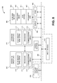
- FIG 8 is a schematic of a computer system 800, in accordance with an embodiment of the present invention.
- the computer system 800 (also referred to as the electronic system 800) as depicted can embody a semiconductor die packaged with an MCI structure according to any of the several disclosed embodiments and their equivalents as set forth in this disclosure.
- the computer system 800 may be a mobile device such as a netbook computer.
- the computer system 800 may be a mobile device such as a wireless smart phone.
- the computer system 800 may be a desktop computer.
- the computer system 800 may be a hand-held reader.
- the electronic system 800 is a computer system that includes a system bus 820 to electrically couple the various components of the electronic system 800.
- the system bus 820 is a single bus or any combination of busses according to various embodiments.
- the electronic system 800 includes a voltage source 830 that provides power to the integrated circuit 810. In some embodiments, the voltage source 830 supplies current to the integrated circuit 810 through the system bus 820.
- the integrated circuit 810 is electrically coupled to the system bus 820 and includes any circuit, or combination of circuits according to an embodiment.
- the integrated circuit 810 includes a processor 812 that can be of any type.
- the processor 812 may mean any type of circuit such as, but not limited to, a microprocessor, a microcontroller, a graphics processor, a digital signal processor, or another processor.
- the processor 812 includes a semiconductor die packaged with an MCI structure, as disclosed herein.
- SRAM embodiments are found in memory caches of the processor.
- circuits that can be included in the integrated circuit 810 are a custom circuit or an application-specific integrated circuit (ASIC), such as a communications circuit 814 for use in wireless devices such as cellular telephones, smart phones, pagers, portable computers, two-way radios, and similar electronic systems.
- ASIC application-specific integrated circuit
- the processor 810 includes on-die memory 816 such as static random-access memory (SRAM).
- the processor 810 includes embedded on-die memory 816 such as embedded dynamic random-access memory (eDRAM).
- the integrated circuit 810 is complemented with a subsequent integrated circuit 811.
- Useful embodiments include a dual processor 813 and a dual communications circuit 815 and dual on-die memory 817 such as SRAM.
- the dual integrated circuit 810 includes embedded on-die memory 817 such as eDRAM.
- the electronic system 800 also includes an external memory 840 that in turn may include one or more memory elements suitable to the particular application, such as a main memory 842 in the form of RAM, one or more hard drives 844, and/or one or more drives that handle removable media 846, such as diskettes, compact disks (CDs), digital variable disks (DVDs), flash memory drives, and other removable media known in the art.
- the external memory 840 may also be embedded memory 848 such as the first die in an embedded TSV die stack, according to an embodiment.
- the electronic system 800 also includes a display device 850 and an audio output 860.
- the electronic system 800 includes an input device such as a controller 870 that may be a keyboard, mouse, trackball, game controller, microphone, voice-recognition device, or any other input device that inputs information into the electronic system 800.
- an input device 870 is a camera.
- an input device 870 is a digital sound recorder.
- an input device 870 is a camera and a digital sound recorder.
- the integrated circuit 810 can be implemented in a number of different embodiments, including a semiconductor die packaged with an MCI structure according to any of the several disclosed embodiments and their equivalents, an electronic system, a computer system, one or more methods of fabricating an integrated circuit, and one or more methods of fabricating an electronic assembly that includes a semiconductor die packaged with an MCI structure according to any of the several disclosed embodiments as set forth herein in the various embodiments and their art-recognized equivalents.
- a foundation substrate may be included, as represented by the dashed line of Figure 8 .
- Passive devices may also be included, as is also depicted in Figure 8 .
- Embodiments of the present invention include semiconductor packages including magnetic core inductor (MCI) structures for integrated voltage regulators.
- MCI magnetic core inductor
- a semiconductor package in an embodiment, includes a package substrate and a semiconductor die coupled to a first surface of the package substrate.
- the semiconductor die has a first plurality of metal-insulator-metal (MIM) capacitor layers thereon.
- the semiconductor package also includes a magnetic core inductor (MCI) die coupled to a second surface of the package substrate.
- the MCI die includes one or more slotted inductors and has a second plurality of MIM capacitor layers thereon.
- each of the one or more slotted inductors of the MCI die includes a plurality of magnetic layers. All the magnetic layers of the plurality of magnetic layers are slotted with a regular pattern.
- each of the one or more slotted inductors of the MCI die comprise a plurality of magnetic layers, and wherein all the magnetic layers of the plurality of magnetic layers are slotted with an irregular pattern.
- each of the one or more slotted inductors of the MCI die comprise a plurality of magnetic layers, and wherein only a portion of, but not all of, the magnetic layers of the plurality of magnetic layers are slotted.
- the one or more slotted inductors, the first plurality of MIM capacitor layers, and the second plurality of MIM capacitor layers form a portion of an integrated voltage regulator for the semiconductor die.
- the first plurality of MIM capacitor layers of the semiconductor die are proximate to the first surface of the package substrate, and the semiconductor die is coupled to the package substrate by a first plurality of contacts.
- the second plurality of MIM capacitor layers of the MCI die are proximate to the second surface of the package substrate, and the MCI die is coupled to the package substrate by a second plurality of contacts.
- the first and second pluralities of contacts are electrically coupled by interconnects of the package substrate.
- the first and second surfaces are on opposing sides of the package substrate.
- the first and second surfaces are on a same side of the package substrate.
- both the semiconductor die and the MCI die are flip-chip bonded to the package substrate.
- the package substrate is a bumpless build-up layer (BBUL) substrate.
- BBUL bumpless build-up layer
- the semiconductor die and the magnetic core inductor die are housed in a core of the package substrate.
- the package substrate is a coreless substrate.
- a magnetic core inductor (MCI) die includes a substrate and one or more slotted inductors disposed above the substrate.
- a plurality of metal-insulator-metal (MIM) capacitor layers is disposed above the one or more slotted inductors.
- each of the one or more slotted inductors includes a plurality of magnetic layers, and all the magnetic layers of the plurality of magnetic layers are slotted with a regular pattern.
- each of the one or more slotted inductors has a plurality of magnetic layers, and all the magnetic layers of the plurality of magnetic layers are slotted with an irregular pattern.
- each of the one or more slotted inductors has a plurality of magnetic layers, and only a portion of, but not all of, the magnetic layers of the plurality of magnetic layers are slotted.
- a method of fabricating a magnetic core inductor (MCI) die involves forming, by a first sputtering process, a first slotted magnetic material structure above a substrate. One or more metal lines is then formed above the first slotted magnetic material structure. The method further involves forming, by a second sputtering process, a second slotted magnetic material structure above the one or more metal lines.
- the first and second sputtering processes each involve sputtering a magnetic material and, subsequently, slotting the magnetic material with a lithography and etching process.
- the first and second sputtering processes each involve sputtering a magnetic material and, subsequently, slotting the magnetic material with a lift-off process.
- the first and second sputtering processes each involve sputtering a magnetic material onto a patterned insulator structure disposed above the one or more metal lines and, subsequently, slotting the magnetic material with a polishing process.
- the first and second sputtering processes each involve sputtering a magnetic material while using a shadow mask for slotting the magnetic material during the sputtering.
- the method further involves forming a plurality of metal-insulator-metal (MIM) capacitor layers above the second slotted magnetic material structure.
- MIM metal-insulator-metal
- the first slotted magnetic material structure has a different slotting pattern than the second slotted magnetic material structure.
Landscapes
- Engineering & Computer Science (AREA)
- Power Engineering (AREA)
- Microelectronics & Electronic Packaging (AREA)
- Semiconductor Integrated Circuits (AREA)
Applications Claiming Priority (1)
| Application Number | Priority Date | Filing Date | Title |
|---|---|---|---|
| US13/801,623 US9129817B2 (en) | 2013-03-13 | 2013-03-13 | Magnetic core inductor (MCI) structures for integrated voltage regulators |
Publications (3)
| Publication Number | Publication Date |
|---|---|
| EP2779236A2 true EP2779236A2 (de) | 2014-09-17 |
| EP2779236A3 EP2779236A3 (de) | 2018-01-03 |
| EP2779236B1 EP2779236B1 (de) | 2020-09-16 |
Family
ID=50231044
Family Applications (1)
| Application Number | Title | Priority Date | Filing Date |
|---|---|---|---|
| EP14158260.1A Active EP2779236B1 (de) | 2013-03-13 | 2014-03-07 | Induktoren mit magnetischem Kern für integrierte Spannungsregler |
Country Status (4)
| Country | Link |
|---|---|
| US (1) | US9129817B2 (de) |
| EP (1) | EP2779236B1 (de) |
| KR (1) | KR101589041B1 (de) |
| CN (1) | CN104051459B (de) |
Cited By (2)
| Publication number | Priority date | Publication date | Assignee | Title |
|---|---|---|---|---|
| US20210398957A1 (en) * | 2020-06-19 | 2021-12-23 | Qualcomm Incorporated | Three-dimensional (3d) integrated circuit with passive elements formed by hybrid bonding |
| EP3971968A1 (de) * | 2020-09-17 | 2022-03-23 | Analog Devices, Inc. | Vorrichtung und verfahren zur abstimmbaren filterung |
Families Citing this family (32)
| Publication number | Priority date | Publication date | Assignee | Title |
|---|---|---|---|---|
| EP2711984A1 (de) * | 2012-09-21 | 2014-03-26 | Nxp B.V. | Metall-Isolier-Metall-Kondensator innerhalb einer Metallisierungsschicht eines integrierten Schaltkreises und Herstellungsverfahren desselben |
| US9871448B2 (en) | 2012-12-31 | 2018-01-16 | Nvidia Corporation | Super N-phase switching mode power supply |
| US9831198B2 (en) * | 2013-08-22 | 2017-11-28 | Nvidia Corporation | Inductors for integrated voltage regulators |
| US9607680B2 (en) * | 2014-03-04 | 2017-03-28 | Apple Inc. | EDRAM/DRAM fabricated capacitors for use in on-chip PMUS and as decoupling capacitors in an integrated EDRAM/DRAM and PMU system |
| US10199152B2 (en) * | 2014-12-03 | 2019-02-05 | Qualcomm Incorporated | Embedded thin film magnetic carrier for integrated voltage regulator |
| US9691701B2 (en) | 2015-07-15 | 2017-06-27 | Apple Inc. | SOC with integrated voltage regulator using preformed MIM capacitor wafer |
| US10290414B2 (en) | 2015-08-31 | 2019-05-14 | Qualcomm Incorporated | Substrate comprising an embedded inductor and a thin film magnetic core |
| US10470309B2 (en) | 2015-09-20 | 2019-11-05 | Qualcomm Incorporated | Inductor and capacitor integrated on a substrate |
| US9935076B1 (en) | 2015-09-30 | 2018-04-03 | Apple Inc. | Structure and method for fabricating a computing system with an integrated voltage regulator module |
| US9911723B2 (en) | 2015-12-18 | 2018-03-06 | Intel Corporation | Magnetic small footprint inductor array module for on-package voltage regulator |
| CN108604587B (zh) * | 2015-12-26 | 2023-01-13 | 英特尔公司 | 片上集成无源器件 |
| US10665385B2 (en) | 2016-10-01 | 2020-05-26 | Intel Corporation | Integrated inductor with adjustable coupling |
| US10593449B2 (en) | 2017-03-30 | 2020-03-17 | International Business Machines Corporation | Magnetic inductor with multiple magnetic layer thicknesses |
| US10607759B2 (en) | 2017-03-31 | 2020-03-31 | International Business Machines Corporation | Method of fabricating a laminated stack of magnetic inductor |
| US10597769B2 (en) | 2017-04-05 | 2020-03-24 | International Business Machines Corporation | Method of fabricating a magnetic stack arrangement of a laminated magnetic inductor |
| US10347411B2 (en) | 2017-05-19 | 2019-07-09 | International Business Machines Corporation | Stress management scheme for fabricating thick magnetic films of an inductor yoke arrangement |
| ES2926349T3 (es) * | 2017-10-26 | 2022-10-25 | Esab Group Inc | Sistema y método de soldadura portátil con técnicas para suministrar CA o CC como corriente de soldadura |
| US10910321B2 (en) | 2017-11-29 | 2021-02-02 | Taiwan Semiconductor Manufacturing Co., Ltd. | Semiconductor device and method of making the same |
| US10396046B2 (en) | 2017-12-29 | 2019-08-27 | Intel Corporation | Substrate assembly with magnetic feature |
| US11984439B2 (en) | 2018-09-14 | 2024-05-14 | Intel Corporation | Microelectronic assemblies |
| US11417593B2 (en) | 2018-09-24 | 2022-08-16 | Intel Corporation | Dies with integrated voltage regulators |
| US11450560B2 (en) | 2018-09-24 | 2022-09-20 | Intel Corporation | Microelectronic assemblies having magnetic core inductors |
| US11462463B2 (en) | 2018-09-27 | 2022-10-04 | Intel Corporation | Microelectronic assemblies having an integrated voltage regulator chiplet |
| US11721677B2 (en) | 2018-12-27 | 2023-08-08 | Intel Corporation | Microelectronic assemblies having an integrated capacitor |
| US11056277B2 (en) | 2018-12-28 | 2021-07-06 | Applied Materials, Inc. | Magnetized substrate carrier apparatus with shadow mask for deposition |
| US11201600B1 (en) | 2020-10-05 | 2021-12-14 | Analog Devices, Inc. | Apparatus and methods for control and calibration of tunable filters |
| US12249584B2 (en) | 2021-05-18 | 2025-03-11 | Intel Corporation | Microelectronic assemblies having integrated magnetic core inductors |
| US12424589B2 (en) | 2021-06-09 | 2025-09-23 | Intel Corporation | Contiguous shield structures in microelectronic assemblies having hybrid bonding |
| US12520506B2 (en) * | 2021-09-24 | 2026-01-06 | Intel Corporation | In situ inductor structure in buildup power planes |
| US11881450B2 (en) | 2021-10-25 | 2024-01-23 | Advanced Micro Devices, Inc. | High voltage tolerant capacitors |
| US12205884B2 (en) | 2021-12-28 | 2025-01-21 | Advanced Micro Devices, Inc. | Method to create MIMcap designs across changing MIMcap structures |
| US12588291B2 (en) | 2023-06-13 | 2026-03-24 | Intel Corporation | Substrates including micro-structured thin film capacitors |
Citations (1)
| Publication number | Priority date | Publication date | Assignee | Title |
|---|---|---|---|---|
| US7518481B2 (en) | 2006-06-30 | 2009-04-14 | Intel Corporation | Slotted magnetic material for integrated circuit inductors |
Family Cites Families (21)
| Publication number | Priority date | Publication date | Assignee | Title |
|---|---|---|---|---|
| US5583424A (en) * | 1993-03-15 | 1996-12-10 | Kabushiki Kaisha Toshiba | Magnetic element for power supply and dc-to-dc converter |
| KR19980033925U (ko) * | 1996-12-10 | 1998-09-05 | 문정환 | 반도체 인덕터 |
| US6175727B1 (en) * | 1998-01-09 | 2001-01-16 | Texas Instruments Israel Ltd. | Suspended printed inductor and LC-type filter constructed therefrom |
| JP2002158135A (ja) * | 2000-11-16 | 2002-05-31 | Tdk Corp | 電子部品 |
| JP4217438B2 (ja) * | 2002-07-26 | 2009-02-04 | Fdk株式会社 | マイクロコンバータ |
| US7098766B2 (en) * | 2004-01-21 | 2006-08-29 | Intel Corporation | Magnetic material for transformers and/or inductors |
| US6970057B2 (en) * | 2004-04-02 | 2005-11-29 | Chi Mei Communication Systems, Inc. | Lowpass filter formed in a multi-layer ceramic |
| US20060088971A1 (en) * | 2004-10-27 | 2006-04-27 | Crawford Ankur M | Integrated inductor and method of fabrication |
| US7652348B1 (en) * | 2006-07-27 | 2010-01-26 | National Semiconductor Corporation | Apparatus and method for wafer level fabrication of high value inductors on semiconductor integrated circuits |
| KR100863009B1 (ko) | 2007-04-11 | 2008-10-13 | 주식회사 하이닉스반도체 | 인덕터가 내장된 기판 구조체 및 그 제조방법 |
| JP2009302418A (ja) | 2008-06-17 | 2009-12-24 | Nec Electronics Corp | 回路装置及びその製造方法 |
| US8884438B2 (en) * | 2008-07-02 | 2014-11-11 | Intel Corporation | Magnetic microinductors for integrated circuit packaging |
| CN101404485B (zh) * | 2008-10-13 | 2010-06-02 | 电子科技大学 | 一种叠层片式滤波器及其制备方法 |
| KR101575387B1 (ko) * | 2009-03-18 | 2015-12-07 | 에이저 시스템즈 엘엘시 | 집적 회로 인덕터 구조체, 전자 시스템 및 집적 회로 인덕터 사이의 자기 커플링 감소 방법 |
| US8907447B2 (en) * | 2010-02-19 | 2014-12-09 | Mingliang Wang | Power inductors in silicon |
| KR20120035394A (ko) * | 2010-10-05 | 2012-04-16 | 삼성전자주식회사 | 수직구조의 전송선로 트랜지션 및 랜드 그리드 어레이 접합를 이용한 단일 칩 패키지를 위한 장치 |
| WO2012087287A1 (en) * | 2010-12-20 | 2012-06-28 | Intel Corporation | Integrated digital- and radio-frequency system-on-chip devices with integral passive devices in package substrates, and methods of making same |
| US9305992B2 (en) * | 2011-06-16 | 2016-04-05 | Altera Corporation | Integrated circuit inductors with intertwined conductors |
| US8982563B2 (en) * | 2011-06-28 | 2015-03-17 | Oracle International Corporation | Chip package to support high-frequency processors |
| US20130257525A1 (en) * | 2012-03-30 | 2013-10-03 | Stephen V. Kosonocky | Circuit board with integrated voltage regulator |
| US8885376B2 (en) * | 2012-05-31 | 2014-11-11 | Analog Devices, Inc. | Switching regulator with integrated resonant circuit for ripple filtering |
-
2013
- 2013-03-13 US US13/801,623 patent/US9129817B2/en active Active
-
2014
- 2014-03-07 EP EP14158260.1A patent/EP2779236B1/de active Active
- 2014-03-10 KR KR1020140027987A patent/KR101589041B1/ko active Active
- 2014-03-12 CN CN201410089273.8A patent/CN104051459B/zh active Active
Patent Citations (2)
| Publication number | Priority date | Publication date | Assignee | Title |
|---|---|---|---|---|
| US7518481B2 (en) | 2006-06-30 | 2009-04-14 | Intel Corporation | Slotted magnetic material for integrated circuit inductors |
| US8108984B2 (en) | 2006-06-30 | 2012-02-07 | Intel Corporation | Method for manufacturing integrated circuit inductors having slotted magnetic material |
Cited By (3)
| Publication number | Priority date | Publication date | Assignee | Title |
|---|---|---|---|---|
| US20210398957A1 (en) * | 2020-06-19 | 2021-12-23 | Qualcomm Incorporated | Three-dimensional (3d) integrated circuit with passive elements formed by hybrid bonding |
| US11605620B2 (en) * | 2020-06-19 | 2023-03-14 | Qualcomm Incorporated | Three-dimensional (3D) integrated circuit with passive elements formed by hybrid bonding |
| EP3971968A1 (de) * | 2020-09-17 | 2022-03-23 | Analog Devices, Inc. | Vorrichtung und verfahren zur abstimmbaren filterung |
Also Published As
| Publication number | Publication date |
|---|---|
| US9129817B2 (en) | 2015-09-08 |
| CN104051459A (zh) | 2014-09-17 |
| KR20140112421A (ko) | 2014-09-23 |
| EP2779236B1 (de) | 2020-09-16 |
| KR101589041B1 (ko) | 2016-01-27 |
| EP2779236A3 (de) | 2018-01-03 |
| CN104051459B (zh) | 2019-07-09 |
| US20140264732A1 (en) | 2014-09-18 |
Similar Documents
| Publication | Publication Date | Title |
|---|---|---|
| EP2779236B1 (de) | Induktoren mit magnetischem Kern für integrierte Spannungsregler | |
| US10256286B2 (en) | Integrated inductor for integrated circuit devices | |
| US20140217547A1 (en) | Semiconductor package with air core inductor (aci) and magnetic core inductor (mci) | |
| US10115661B2 (en) | Substrate-less discrete coupled inductor structure | |
| KR102108707B1 (ko) | 기판 내 커플링된 인덕터 구조 | |
| US10008557B2 (en) | Vertical meander inductor for small core voltage regulators | |
| US9142347B2 (en) | Semiconductor package with air core inductor (ACI) having a metal-density layer unit of fractal geometry | |
| US9006862B2 (en) | Electronic semiconductor device with integrated inductor, and manufacturing method | |
| CN107077950B (zh) | 用于集成电压调节器的嵌入式薄膜磁载体 | |
| WO2017052530A1 (en) | High current magnetic thin film inductors |
Legal Events
| Date | Code | Title | Description |
|---|---|---|---|
| 17P | Request for examination filed |
Effective date: 20140307 |
|
| AK | Designated contracting states |
Kind code of ref document: A2 Designated state(s): AL AT BE BG CH CY CZ DE DK EE ES FI FR GB GR HR HU IE IS IT LI LT LU LV MC MK MT NL NO PL PT RO RS SE SI SK SM TR |
|
| AX | Request for extension of the european patent |
Extension state: BA ME |
|
| PUAI | Public reference made under article 153(3) epc to a published international application that has entered the european phase |
Free format text: ORIGINAL CODE: 0009012 |
|
| REG | Reference to a national code |
Ref country code: DE Ref legal event code: R079 Ref document number: 602014070188 Country of ref document: DE Free format text: PREVIOUS MAIN CLASS: H01L0023640000 Ipc: H01F0017060000 |
|
| PUAL | Search report despatched |
Free format text: ORIGINAL CODE: 0009013 |
|
| AK | Designated contracting states |
Kind code of ref document: A3 Designated state(s): AL AT BE BG CH CY CZ DE DK EE ES FI FR GB GR HR HU IE IS IT LI LT LU LV MC MK MT NL NO PL PT RO RS SE SI SK SM TR |
|
| AX | Request for extension of the european patent |
Extension state: BA ME |
|
| RIC1 | Information provided on ipc code assigned before grant |
Ipc: H01F 17/06 20060101AFI20171130BHEP Ipc: H01F 17/00 20060101ALI20171130BHEP Ipc: H01L 25/16 20060101ALI20171130BHEP Ipc: H01L 49/02 20060101ALI20171130BHEP Ipc: H01L 23/64 20060101ALI20171130BHEP |
|
| STAA | Information on the status of an ep patent application or granted ep patent |
Free format text: STATUS: EXAMINATION IS IN PROGRESS |
|
| 17Q | First examination report despatched |
Effective date: 20180205 |
|
| RBV | Designated contracting states (corrected) |
Designated state(s): AL AT BE BG CH CY CZ DE DK EE ES FI FR GB GR HR HU IE IS IT LI LT LU LV MC MK MT NL NO PL PT RO RS SE SI SK SM TR |
|
| GRAP | Despatch of communication of intention to grant a patent |
Free format text: ORIGINAL CODE: EPIDOSNIGR1 |
|
| STAA | Information on the status of an ep patent application or granted ep patent |
Free format text: STATUS: GRANT OF PATENT IS INTENDED |
|
| INTG | Intention to grant announced |
Effective date: 20200407 |
|
| RIN1 | Information on inventor provided before grant (corrected) |
Inventor name: BHARATH, KRISHNA Inventor name: O'BRIEN, KEVIN P. Inventor name: ELSHERBINI, ADEL A. Inventor name: BRAUNISCH, HENNING |
|
| GRAS | Grant fee paid |
Free format text: ORIGINAL CODE: EPIDOSNIGR3 |
|
| GRAA | (expected) grant |
Free format text: ORIGINAL CODE: 0009210 |
|
| STAA | Information on the status of an ep patent application or granted ep patent |
Free format text: STATUS: THE PATENT HAS BEEN GRANTED |
|
| AK | Designated contracting states |
Kind code of ref document: B1 Designated state(s): AL AT BE BG CH CY CZ DE DK EE ES FI FR GB GR HR HU IE IS IT LI LT LU LV MC MK MT NL NO PL PT RO RS SE SI SK SM TR |
|
| REG | Reference to a national code |
Ref country code: GB Ref legal event code: FG4D |
|
| REG | Reference to a national code |
Ref country code: CH Ref legal event code: EP |
|
| REG | Reference to a national code |
Ref country code: DE Ref legal event code: R096 Ref document number: 602014070188 Country of ref document: DE |
|
| REG | Reference to a national code |
Ref country code: IE Ref legal event code: FG4D |
|
| REG | Reference to a national code |
Ref country code: AT Ref legal event code: REF Ref document number: 1314892 Country of ref document: AT Kind code of ref document: T Effective date: 20201015 |
|
| REG | Reference to a national code |
Ref country code: NL Ref legal event code: FP |
|
| PG25 | Lapsed in a contracting state [announced via postgrant information from national office to epo] |
Ref country code: NO Free format text: LAPSE BECAUSE OF FAILURE TO SUBMIT A TRANSLATION OF THE DESCRIPTION OR TO PAY THE FEE WITHIN THE PRESCRIBED TIME-LIMIT Effective date: 20201216 Ref country code: GR Free format text: LAPSE BECAUSE OF FAILURE TO SUBMIT A TRANSLATION OF THE DESCRIPTION OR TO PAY THE FEE WITHIN THE PRESCRIBED TIME-LIMIT Effective date: 20201217 Ref country code: BG Free format text: LAPSE BECAUSE OF FAILURE TO SUBMIT A TRANSLATION OF THE DESCRIPTION OR TO PAY THE FEE WITHIN THE PRESCRIBED TIME-LIMIT Effective date: 20201216 Ref country code: SE Free format text: LAPSE BECAUSE OF FAILURE TO SUBMIT A TRANSLATION OF THE DESCRIPTION OR TO PAY THE FEE WITHIN THE PRESCRIBED TIME-LIMIT Effective date: 20200916 Ref country code: HR Free format text: LAPSE BECAUSE OF FAILURE TO SUBMIT A TRANSLATION OF THE DESCRIPTION OR TO PAY THE FEE WITHIN THE PRESCRIBED TIME-LIMIT Effective date: 20200916 Ref country code: FI Free format text: LAPSE BECAUSE OF FAILURE TO SUBMIT A TRANSLATION OF THE DESCRIPTION OR TO PAY THE FEE WITHIN THE PRESCRIBED TIME-LIMIT Effective date: 20200916 |
|
| REG | Reference to a national code |
Ref country code: AT Ref legal event code: MK05 Ref document number: 1314892 Country of ref document: AT Kind code of ref document: T Effective date: 20200916 |
|
| PG25 | Lapsed in a contracting state [announced via postgrant information from national office to epo] |
Ref country code: RS Free format text: LAPSE BECAUSE OF FAILURE TO SUBMIT A TRANSLATION OF THE DESCRIPTION OR TO PAY THE FEE WITHIN THE PRESCRIBED TIME-LIMIT Effective date: 20200916 Ref country code: LV Free format text: LAPSE BECAUSE OF FAILURE TO SUBMIT A TRANSLATION OF THE DESCRIPTION OR TO PAY THE FEE WITHIN THE PRESCRIBED TIME-LIMIT Effective date: 20200916 |
|
| REG | Reference to a national code |
Ref country code: LT Ref legal event code: MG4D |
|
| PG25 | Lapsed in a contracting state [announced via postgrant information from national office to epo] |
Ref country code: EE Free format text: LAPSE BECAUSE OF FAILURE TO SUBMIT A TRANSLATION OF THE DESCRIPTION OR TO PAY THE FEE WITHIN THE PRESCRIBED TIME-LIMIT Effective date: 20200916 Ref country code: CZ Free format text: LAPSE BECAUSE OF FAILURE TO SUBMIT A TRANSLATION OF THE DESCRIPTION OR TO PAY THE FEE WITHIN THE PRESCRIBED TIME-LIMIT Effective date: 20200916 Ref country code: PT Free format text: LAPSE BECAUSE OF FAILURE TO SUBMIT A TRANSLATION OF THE DESCRIPTION OR TO PAY THE FEE WITHIN THE PRESCRIBED TIME-LIMIT Effective date: 20210118 Ref country code: LT Free format text: LAPSE BECAUSE OF FAILURE TO SUBMIT A TRANSLATION OF THE DESCRIPTION OR TO PAY THE FEE WITHIN THE PRESCRIBED TIME-LIMIT Effective date: 20200916 Ref country code: RO Free format text: LAPSE BECAUSE OF FAILURE TO SUBMIT A TRANSLATION OF THE DESCRIPTION OR TO PAY THE FEE WITHIN THE PRESCRIBED TIME-LIMIT Effective date: 20200916 Ref country code: SM Free format text: LAPSE BECAUSE OF FAILURE TO SUBMIT A TRANSLATION OF THE DESCRIPTION OR TO PAY THE FEE WITHIN THE PRESCRIBED TIME-LIMIT Effective date: 20200916 |
|
| PG25 | Lapsed in a contracting state [announced via postgrant information from national office to epo] |
Ref country code: AL Free format text: LAPSE BECAUSE OF FAILURE TO SUBMIT A TRANSLATION OF THE DESCRIPTION OR TO PAY THE FEE WITHIN THE PRESCRIBED TIME-LIMIT Effective date: 20200916 Ref country code: AT Free format text: LAPSE BECAUSE OF FAILURE TO SUBMIT A TRANSLATION OF THE DESCRIPTION OR TO PAY THE FEE WITHIN THE PRESCRIBED TIME-LIMIT Effective date: 20200916 Ref country code: ES Free format text: LAPSE BECAUSE OF FAILURE TO SUBMIT A TRANSLATION OF THE DESCRIPTION OR TO PAY THE FEE WITHIN THE PRESCRIBED TIME-LIMIT Effective date: 20200916 Ref country code: PL Free format text: LAPSE BECAUSE OF FAILURE TO SUBMIT A TRANSLATION OF THE DESCRIPTION OR TO PAY THE FEE WITHIN THE PRESCRIBED TIME-LIMIT Effective date: 20200916 Ref country code: IS Free format text: LAPSE BECAUSE OF FAILURE TO SUBMIT A TRANSLATION OF THE DESCRIPTION OR TO PAY THE FEE WITHIN THE PRESCRIBED TIME-LIMIT Effective date: 20210116 |
|
| REG | Reference to a national code |
Ref country code: DE Ref legal event code: R097 Ref document number: 602014070188 Country of ref document: DE |
|
| PG25 | Lapsed in a contracting state [announced via postgrant information from national office to epo] |
Ref country code: SK Free format text: LAPSE BECAUSE OF FAILURE TO SUBMIT A TRANSLATION OF THE DESCRIPTION OR TO PAY THE FEE WITHIN THE PRESCRIBED TIME-LIMIT Effective date: 20200916 |
|
| PLBE | No opposition filed within time limit |
Free format text: ORIGINAL CODE: 0009261 |
|
| STAA | Information on the status of an ep patent application or granted ep patent |
Free format text: STATUS: NO OPPOSITION FILED WITHIN TIME LIMIT |
|
| 26N | No opposition filed |
Effective date: 20210617 |
|
| PG25 | Lapsed in a contracting state [announced via postgrant information from national office to epo] |
Ref country code: SI Free format text: LAPSE BECAUSE OF FAILURE TO SUBMIT A TRANSLATION OF THE DESCRIPTION OR TO PAY THE FEE WITHIN THE PRESCRIBED TIME-LIMIT Effective date: 20200916 Ref country code: DK Free format text: LAPSE BECAUSE OF FAILURE TO SUBMIT A TRANSLATION OF THE DESCRIPTION OR TO PAY THE FEE WITHIN THE PRESCRIBED TIME-LIMIT Effective date: 20200916 |
|
| PG25 | Lapsed in a contracting state [announced via postgrant information from national office to epo] |
Ref country code: IT Free format text: LAPSE BECAUSE OF FAILURE TO SUBMIT A TRANSLATION OF THE DESCRIPTION OR TO PAY THE FEE WITHIN THE PRESCRIBED TIME-LIMIT Effective date: 20200916 Ref country code: MC Free format text: LAPSE BECAUSE OF FAILURE TO SUBMIT A TRANSLATION OF THE DESCRIPTION OR TO PAY THE FEE WITHIN THE PRESCRIBED TIME-LIMIT Effective date: 20200916 |
|
| REG | Reference to a national code |
Ref country code: CH Ref legal event code: PL |
|
| REG | Reference to a national code |
Ref country code: BE Ref legal event code: MM Effective date: 20210331 |
|
| PG25 | Lapsed in a contracting state [announced via postgrant information from national office to epo] |
Ref country code: LI Free format text: LAPSE BECAUSE OF NON-PAYMENT OF DUE FEES Effective date: 20210331 Ref country code: LU Free format text: LAPSE BECAUSE OF NON-PAYMENT OF DUE FEES Effective date: 20210307 Ref country code: CH Free format text: LAPSE BECAUSE OF NON-PAYMENT OF DUE FEES Effective date: 20210331 Ref country code: IE Free format text: LAPSE BECAUSE OF NON-PAYMENT OF DUE FEES Effective date: 20210307 |
|
| PG25 | Lapsed in a contracting state [announced via postgrant information from national office to epo] |
Ref country code: BE Free format text: LAPSE BECAUSE OF NON-PAYMENT OF DUE FEES Effective date: 20210331 |
|
| PG25 | Lapsed in a contracting state [announced via postgrant information from national office to epo] |
Ref country code: HU Free format text: LAPSE BECAUSE OF FAILURE TO SUBMIT A TRANSLATION OF THE DESCRIPTION OR TO PAY THE FEE WITHIN THE PRESCRIBED TIME-LIMIT; INVALID AB INITIO Effective date: 20140307 |
|
| P01 | Opt-out of the competence of the unified patent court (upc) registered |
Effective date: 20230518 |
|
| PG25 | Lapsed in a contracting state [announced via postgrant information from national office to epo] |
Ref country code: CY Free format text: LAPSE BECAUSE OF FAILURE TO SUBMIT A TRANSLATION OF THE DESCRIPTION OR TO PAY THE FEE WITHIN THE PRESCRIBED TIME-LIMIT Effective date: 20200916 |
|
| PG25 | Lapsed in a contracting state [announced via postgrant information from national office to epo] |
Ref country code: MK Free format text: LAPSE BECAUSE OF FAILURE TO SUBMIT A TRANSLATION OF THE DESCRIPTION OR TO PAY THE FEE WITHIN THE PRESCRIBED TIME-LIMIT Effective date: 20200916 |
|
| PG25 | Lapsed in a contracting state [announced via postgrant information from national office to epo] |
Ref country code: MT Free format text: LAPSE BECAUSE OF FAILURE TO SUBMIT A TRANSLATION OF THE DESCRIPTION OR TO PAY THE FEE WITHIN THE PRESCRIBED TIME-LIMIT Effective date: 20200916 |
|
| PGFP | Annual fee paid to national office [announced via postgrant information from national office to epo] |
Ref country code: NL Payment date: 20241203 Year of fee payment: 12 |
|
| PGFP | Annual fee paid to national office [announced via postgrant information from national office to epo] |
Ref country code: FR Payment date: 20241129 Year of fee payment: 12 |
|
| PG25 | Lapsed in a contracting state [announced via postgrant information from national office to epo] |
Ref country code: TR Free format text: LAPSE BECAUSE OF FAILURE TO SUBMIT A TRANSLATION OF THE DESCRIPTION OR TO PAY THE FEE WITHIN THE PRESCRIBED TIME-LIMIT Effective date: 20200916 |
|
| PGFP | Annual fee paid to national office [announced via postgrant information from national office to epo] |
Ref country code: GB Payment date: 20260223 Year of fee payment: 13 |
|
| PGFP | Annual fee paid to national office [announced via postgrant information from national office to epo] |
Ref country code: DE Payment date: 20260102 Year of fee payment: 13 |