EP2779272B1 - Dreidimensionales biokompatibles energieversorgungselement und methode zu dessen herstellung - Google Patents
Dreidimensionales biokompatibles energieversorgungselement und methode zu dessen herstellung Download PDFInfo
- Publication number
- EP2779272B1 EP2779272B1 EP14160054.4A EP14160054A EP2779272B1 EP 2779272 B1 EP2779272 B1 EP 2779272B1 EP 14160054 A EP14160054 A EP 14160054A EP 2779272 B1 EP2779272 B1 EP 2779272B1
- Authority
- EP
- European Patent Office
- Prior art keywords
- anode
- cathode
- dimensional
- dimensional surface
- conductive traces
- Prior art date
- Legal status (The legal status is an assumption and is not a legal conclusion. Google has not performed a legal analysis and makes no representation as to the accuracy of the status listed.)
- Active
Links
Images



Classifications
-
- H—ELECTRICITY
- H01—ELECTRIC ELEMENTS
- H01M—PROCESSES OR MEANS, e.g. BATTERIES, FOR THE DIRECT CONVERSION OF CHEMICAL ENERGY INTO ELECTRICAL ENERGY
- H01M10/00—Secondary cells; Manufacture thereof
- H01M10/04—Construction or manufacture in general
- H01M10/0436—Small-sized flat cells or batteries for portable equipment
-
- H—ELECTRICITY
- H01—ELECTRIC ELEMENTS
- H01M—PROCESSES OR MEANS, e.g. BATTERIES, FOR THE DIRECT CONVERSION OF CHEMICAL ENERGY INTO ELECTRICAL ENERGY
- H01M4/00—Electrodes
- H01M4/02—Electrodes composed of, or comprising, active material
- H01M4/04—Processes of manufacture in general
- H01M4/0402—Methods of deposition of the material
- H01M4/0414—Methods of deposition of the material by screen printing
-
- H—ELECTRICITY
- H01—ELECTRIC ELEMENTS
- H01M—PROCESSES OR MEANS, e.g. BATTERIES, FOR THE DIRECT CONVERSION OF CHEMICAL ENERGY INTO ELECTRICAL ENERGY
- H01M4/00—Electrodes
- H01M4/02—Electrodes composed of, or comprising, active material
- H01M4/06—Electrodes for primary cells
- H01M4/08—Processes of manufacture
-
- H—ELECTRICITY
- H01—ELECTRIC ELEMENTS
- H01M—PROCESSES OR MEANS, e.g. BATTERIES, FOR THE DIRECT CONVERSION OF CHEMICAL ENERGY INTO ELECTRICAL ENERGY
- H01M4/00—Electrodes
- H01M4/02—Electrodes composed of, or comprising, active material
- H01M4/24—Electrodes for alkaline accumulators
- H01M4/244—Zinc electrodes
-
- H—ELECTRICITY
- H01—ELECTRIC ELEMENTS
- H01M—PROCESSES OR MEANS, e.g. BATTERIES, FOR THE DIRECT CONVERSION OF CHEMICAL ENERGY INTO ELECTRICAL ENERGY
- H01M4/00—Electrodes
- H01M4/02—Electrodes composed of, or comprising, active material
- H01M4/24—Electrodes for alkaline accumulators
- H01M4/26—Processes of manufacture
-
- H—ELECTRICITY
- H01—ELECTRIC ELEMENTS
- H01M—PROCESSES OR MEANS, e.g. BATTERIES, FOR THE DIRECT CONVERSION OF CHEMICAL ENERGY INTO ELECTRICAL ENERGY
- H01M4/00—Electrodes
- H01M4/02—Electrodes composed of, or comprising, active material
- H01M4/36—Selection of substances as active materials, active masses, active liquids
- H01M4/38—Selection of substances as active materials, active masses, active liquids of elements or alloys
-
- H—ELECTRICITY
- H01—ELECTRIC ELEMENTS
- H01M—PROCESSES OR MEANS, e.g. BATTERIES, FOR THE DIRECT CONVERSION OF CHEMICAL ENERGY INTO ELECTRICAL ENERGY
- H01M50/00—Constructional details or processes of manufacture of the non-active parts of electrochemical cells other than fuel cells, e.g. hybrid cells
- H01M50/10—Primary casings; Jackets or wrappings
-
- H—ELECTRICITY
- H01—ELECTRIC ELEMENTS
- H01M—PROCESSES OR MEANS, e.g. BATTERIES, FOR THE DIRECT CONVERSION OF CHEMICAL ENERGY INTO ELECTRICAL ENERGY
- H01M50/00—Constructional details or processes of manufacture of the non-active parts of electrochemical cells other than fuel cells, e.g. hybrid cells
- H01M50/10—Primary casings; Jackets or wrappings
- H01M50/116—Primary casings; Jackets or wrappings characterised by the material
- H01M50/121—Organic material
-
- H—ELECTRICITY
- H01—ELECTRIC ELEMENTS
- H01M—PROCESSES OR MEANS, e.g. BATTERIES, FOR THE DIRECT CONVERSION OF CHEMICAL ENERGY INTO ELECTRICAL ENERGY
- H01M50/00—Constructional details or processes of manufacture of the non-active parts of electrochemical cells other than fuel cells, e.g. hybrid cells
- H01M50/10—Primary casings; Jackets or wrappings
- H01M50/116—Primary casings; Jackets or wrappings characterised by the material
- H01M50/124—Primary casings; Jackets or wrappings characterised by the material having a layered structure
- H01M50/126—Primary casings; Jackets or wrappings characterised by the material having a layered structure comprising three or more layers
- H01M50/129—Primary casings; Jackets or wrappings characterised by the material having a layered structure comprising three or more layers with two or more layers of only organic material
-
- H—ELECTRICITY
- H01—ELECTRIC ELEMENTS
- H01M—PROCESSES OR MEANS, e.g. BATTERIES, FOR THE DIRECT CONVERSION OF CHEMICAL ENERGY INTO ELECTRICAL ENERGY
- H01M6/00—Primary cells; Manufacture thereof
- H01M6/22—Immobilising of electrolyte
-
- H—ELECTRICITY
- H01—ELECTRIC ELEMENTS
- H01M—PROCESSES OR MEANS, e.g. BATTERIES, FOR THE DIRECT CONVERSION OF CHEMICAL ENERGY INTO ELECTRICAL ENERGY
- H01M6/00—Primary cells; Manufacture thereof
- H01M6/40—Printed batteries, e.g. thin film batteries
-
- A—HUMAN NECESSITIES
- A61—MEDICAL OR VETERINARY SCIENCE; HYGIENE
- A61N—ELECTROTHERAPY; MAGNETOTHERAPY; RADIATION THERAPY; ULTRASOUND THERAPY
- A61N1/00—Electrotherapy; Circuits therefor
-
- H—ELECTRICITY
- H01—ELECTRIC ELEMENTS
- H01M—PROCESSES OR MEANS, e.g. BATTERIES, FOR THE DIRECT CONVERSION OF CHEMICAL ENERGY INTO ELECTRICAL ENERGY
- H01M10/00—Secondary cells; Manufacture thereof
- H01M10/05—Accumulators with non-aqueous electrolyte
- H01M10/056—Accumulators with non-aqueous electrolyte characterised by the materials used as electrolytes, e.g. mixed inorganic/organic electrolytes
-
- H—ELECTRICITY
- H01—ELECTRIC ELEMENTS
- H01M—PROCESSES OR MEANS, e.g. BATTERIES, FOR THE DIRECT CONVERSION OF CHEMICAL ENERGY INTO ELECTRICAL ENERGY
- H01M10/00—Secondary cells; Manufacture thereof
- H01M10/05—Accumulators with non-aqueous electrolyte
- H01M10/058—Construction or manufacture
- H01M10/0585—Construction or manufacture of accumulators having only flat construction elements, i.e. flat positive electrodes, flat negative electrodes and flat separators
-
- H—ELECTRICITY
- H01—ELECTRIC ELEMENTS
- H01M—PROCESSES OR MEANS, e.g. BATTERIES, FOR THE DIRECT CONVERSION OF CHEMICAL ENERGY INTO ELECTRICAL ENERGY
- H01M2220/00—Batteries for particular applications
- H01M2220/30—Batteries in portable systems, e.g. mobile phone, laptop
-
- H—ELECTRICITY
- H01—ELECTRIC ELEMENTS
- H01M—PROCESSES OR MEANS, e.g. BATTERIES, FOR THE DIRECT CONVERSION OF CHEMICAL ENERGY INTO ELECTRICAL ENERGY
- H01M2300/00—Electrolytes
- H01M2300/0085—Immobilising or gelification of electrolyte
-
- H—ELECTRICITY
- H01—ELECTRIC ELEMENTS
- H01M—PROCESSES OR MEANS, e.g. BATTERIES, FOR THE DIRECT CONVERSION OF CHEMICAL ENERGY INTO ELECTRICAL ENERGY
- H01M4/00—Electrodes
- H01M4/02—Electrodes composed of, or comprising, active material
- H01M4/36—Selection of substances as active materials, active masses, active liquids
- H01M4/38—Selection of substances as active materials, active masses, active liquids of elements or alloys
- H01M4/42—Alloys based on zinc
-
- H—ELECTRICITY
- H01—ELECTRIC ELEMENTS
- H01M—PROCESSES OR MEANS, e.g. BATTERIES, FOR THE DIRECT CONVERSION OF CHEMICAL ENERGY INTO ELECTRICAL ENERGY
- H01M4/00—Electrodes
- H01M4/02—Electrodes composed of, or comprising, active material
- H01M4/64—Carriers or collectors
- H01M4/66—Selection of materials
- H01M4/661—Metal or alloys, e.g. alloy coatings
-
- H—ELECTRICITY
- H01—ELECTRIC ELEMENTS
- H01M—PROCESSES OR MEANS, e.g. BATTERIES, FOR THE DIRECT CONVERSION OF CHEMICAL ENERGY INTO ELECTRICAL ENERGY
- H01M6/00—Primary cells; Manufacture thereof
- H01M6/04—Cells with aqueous electrolyte
- H01M6/06—Dry cells, i.e. cells wherein the electrolyte is rendered non-fluid
-
- Y—GENERAL TAGGING OF NEW TECHNOLOGICAL DEVELOPMENTS; GENERAL TAGGING OF CROSS-SECTIONAL TECHNOLOGIES SPANNING OVER SEVERAL SECTIONS OF THE IPC; TECHNICAL SUBJECTS COVERED BY FORMER USPC CROSS-REFERENCE ART COLLECTIONS [XRACs] AND DIGESTS
- Y02—TECHNOLOGIES OR APPLICATIONS FOR MITIGATION OR ADAPTATION AGAINST CLIMATE CHANGE
- Y02E—REDUCTION OF GREENHOUSE GAS [GHG] EMISSIONS, RELATED TO ENERGY GENERATION, TRANSMISSION OR DISTRIBUTION
- Y02E60/00—Enabling technologies; Technologies with a potential or indirect contribution to GHG emissions mitigation
- Y02E60/10—Energy storage using batteries
-
- Y—GENERAL TAGGING OF NEW TECHNOLOGICAL DEVELOPMENTS; GENERAL TAGGING OF CROSS-SECTIONAL TECHNOLOGIES SPANNING OVER SEVERAL SECTIONS OF THE IPC; TECHNICAL SUBJECTS COVERED BY FORMER USPC CROSS-REFERENCE ART COLLECTIONS [XRACs] AND DIGESTS
- Y02—TECHNOLOGIES OR APPLICATIONS FOR MITIGATION OR ADAPTATION AGAINST CLIMATE CHANGE
- Y02P—CLIMATE CHANGE MITIGATION TECHNOLOGIES IN THE PRODUCTION OR PROCESSING OF GOODS
- Y02P70/00—Climate change mitigation technologies in the production process for final industrial or consumer products
- Y02P70/50—Manufacturing or production processes characterised by the final manufactured product
-
- Y—GENERAL TAGGING OF NEW TECHNOLOGICAL DEVELOPMENTS; GENERAL TAGGING OF CROSS-SECTIONAL TECHNOLOGIES SPANNING OVER SEVERAL SECTIONS OF THE IPC; TECHNICAL SUBJECTS COVERED BY FORMER USPC CROSS-REFERENCE ART COLLECTIONS [XRACs] AND DIGESTS
- Y10—TECHNICAL SUBJECTS COVERED BY FORMER USPC
- Y10T—TECHNICAL SUBJECTS COVERED BY FORMER US CLASSIFICATION
- Y10T29/00—Metal working
- Y10T29/49—Method of mechanical manufacture
- Y10T29/49002—Electrical device making
- Y10T29/49108—Electric battery cell making
- Y10T29/49115—Electric battery cell making including coating or impregnating
Definitions
- a three-dimensional biocompatible energization element and methods of forming it are described.
- the methods to form the three-dimensional biocompatible energization elements involve forming conductive traces on the three-dimensional surfaces and depositing active elements of the energization elements on the conductive traces.
- the active elements are sealed with a biocompatible material.
- a field of use for the methods may include any biocompatible device or product that requires energization elements.
- Some medical devices may include components such as semiconductor components that perform a variety of functions that can be incorporated into many biocompatible and/or implantable devices.
- semiconductor components require energy and, thus, energization elements must also be included in such biocompatible devices.
- the topology and relatively small size of the biocompatible devices creates novel and challenging environments for the definition of various functionalities. In many embodiments, it is important to provide safe, reliable, compact and cost effective means to energize the semiconductor components within the biocompatible devices. Therefore, a need exists for novel embodiments of forming three-dimensional biocompatible energization elements for their implantation within or upon biocompatible devices.
- the three-dimensional biocompatible energization elements are designed for use in or proximate to the body of a living organism.
- the methods and apparatus presented herein relate to forming three-dimensional biocompatible energization elements for inclusion within or on three-dimensional biocompatible devices.
- FIG. 1 illustrates a method for forming energization elements by printing techniques.
- printing techniques is broadly represented by the process of depositing or leaving a deposit of material in defined locations.
- additive techniques where material is placed at certain isolated locations upon a surface
- subtractive techniques where a coating may be subsequently patterned to allow for the removal of material in selected locations which thereafter may result in a pattern of isolated locations are also within the scope of this application.
- a pair of conductive traces 120 and 130 and an example printer 110 are depicted in FIG. 1 .
- Two conductive traces 120 and 130 are illustrated in FIG. 1 and, in some embodiments, two or more conductive traces can be included or formed on the three-dimensional surface.
- Each conductive trace is preferably electrically conductive to provide an electrical potential for forming the anode, the cathode, and other active elements.
- the conductive traces 120 and 130 can be electrically connected to one another to provide an electrical connection for the active elements of the energization elements.
- the conductive traces 120 and 130 can lay relatively close to a neighboring conductive trace.
- the neighboring conductive traces may represent the opposite polarity electrode or chemistry type when active elements are produced upon these traces.
- one of conductive traces 120 and 130 can be the location of an anode and the other can be the location of a cathode.
- the printer 110 may have a printing head 115, which can control the distribution of material into a defined, localized region.
- the printing head 115 may include a stainless steel needle which may have an exit orifice sized from, for example, 150 microns to 300 microns.
- the printing head 115 can be made a precision stainless steel tip for cathode and anode printing and, more specifically, a 25 gauge, 27 gauge, 30 gauge or 32 gauge by 1,4" length tip.
- Other examples of printing heads 115 are also within the scope of this application and can vary depending on different factors, such as precision requirements, chemical compositions to be deposited, or the like.
- the anode represents the negative (-) potential connection of an energization element and the cathode represents the positive (+) potential connection of an energization element to incorporated devices. While particular orientations of the anode and the cathode are described throughout the following description, the orientations of the anode and the cathode can be changed, e.g., reversed. In some embodiments, the cathode can be configured to have a larger surface area than the anode.
- the printer 110 may contain and be loaded with a mixture of a variety of active and supportive materials for use in forming various components of an energization element. These combinations of materials may contain an active anode or cathode materials in microscopic powder form. In some embodiments, the various materials may be processed in sorting manners, such as sieving, to result in a mixture which has a narrow and controlled size distribution of powder constituents. In one example, one anode mixture may contain a zinc powder formulation comprising powder components small enough to pass through a 25-micron sieve. By restricting the size of the components in the various materials, the size of the orifice of the printing head 115 can be relatively small, such as 100 to 200 microns. As such, a battery that includes complex three dimensional contours and is very small in size can be formed.
- Table 1 shows an exemplary mixture of components for a printable anode formulation.
- Table 2 shows an exemplary mixture of components for a printable cathode formulation.
- Table 3 shows an exemplary mixture of components for an optional printable bridge element formulation.
- solvents, fillers, binders, etc. can be included in the exemplary mixtures. It is also apparent to one of ordinary skill in the art that numerous modifications to the makeup, constituents, amounts of constituents, nature of the constituents and other such changes may be within the scope of this application.
- Table 1 Exemplary Anode Mixture Material Function/Description Poly(ethylene oxide) in distilled water Diluted binder Zinc alloy powder including Bismuth and Indium Active anode Aerosil R972 Rheology modifier/stabilizer Poly(ethylene glycol) in distilled water Plasticizer Triton X-100 in distilled water Surfactant
- Table 2 Exemplary Cathode Mixture Material Function Poly(ethylene oxide) in distilled water Diluted binder Electrolytic manganese dioxide powder Active cathode Aerosil R972 Rheology modifier Silver flake Conductive additive Triton X-100 in distilled water
- Table 3 Exemplary Binder "Bridge” Separator Mixture Material Function Poly(ethylene oxide)in distilled water Diluted binder Barium Sulfate Filler Aerosil R972 Rheology modifier Poly(ethylene glycol) in distilled water Plasticizer Triton X-100 in distilled water Surfactant
- the printer 110 When the printer 110 is loaded with a mixture, its printing head 115 can move relative to the three-dimensional surface or the three-dimensional surface may move relative to the printing head 115, by control mechanisms of the printer 110, such as automation used to locate the printing head 115 in a three-dimensional location above the conductive trace 120. Because the printing head 115 can be moved laterally, vertically, and/or longitudinally, the printing head 115 can deposit the chemical mixture over any three-dimensional surface with precision. Accordingly, the three-dimensional surface is not a single planar surface, but can include two or more non-parallel planes. In addition, the three-dimensional surface can include any number of shapes, projections, contours, irregularities, and/or topographies. For example, an energized lens, a pill, and a valve including micro scale contoured shapes are examples of devices with three-dimensional surfaces.
- an automated dispenser or inkjet-type printer can be used as the printer 110.
- the printing head 115 can be configured to dispense some of the chemical mixture from the printer 110.
- the amount or rate of chemical mixture that is dispensed depends on, for example, the desired thickness of the component and/or the topography of the three-dimensional surface. For example, a thicker component can be deposited by increasing the amount or rate of the chemical mixture that is dispensed.
- a line, multiple lines, a dot, a layer, and/or multiple dots may be formed into an appropriate feature, such as anode 140 on conductive trace 120.
- Different patterns of various chemical mixtures may be printed anywhere on the three-dimensional surface, both inside and outside of the conductive traces 120 and 130, to form different components of the energization element.
- the chemical mixture can completely cover the conductive traces 120 and 130, whereas in other embodiments, the chemical mixture can partially cover the conductive traces 120 and 130.
- the conductive traces 120 and 130 may function as electrical interconnections for the energization elements. For example, if two energization elements are being formed on a three-dimensional surface, the energization elements can be connected in serial using one or more of the conductive traces 120 and 130.
- FIG. 2 an example of a printed energization element 200 on a three-dimensional substrate including conductive traces 230 and 240 is illustrated where the electrode deposits 210 and 220 do not cover the entirety of their respective conductive traces 230 and 240.
- the electrode deposits 210 and 220 can completely cover or even slightly transcend the conductive traces 230 and 240.
- FIG. 2 illustrates an example of printed features that lie upon conductive traces, such as the example anode 210 which lies upon the conductive trace 230 and the example cathode 220 which lies upon the conductive trace 240, other features can be printed anywhere on the three-dimensional surface.
- the bridge 250 may be deposited between the conductive traces 230 and 240.
- any other features can be positioned, printed, and/or deposited anywhere on the three-dimensional surface.
- FIG. 3 an example of a cross-section of an energization element 300 on a three-dimensional surface 310 is illustrated.
- the three-dimensional surface 310 is shown as being relatively smooth, the three-dimensional surface 310 can include any number of shapes, projections, contours, irregularities, and/or topographies.
- the three-dimensional surface 310 can be made of any electrically and/or physically insulating material, such as a monomeric composition and/or prepolymer material which may be crosslinked, silicone elastomers or hydrogels, poly(ethylene oxide), poly(acrylic acid), silicone hydrogels, fluorosilicone hydrogels, polypropylene, polystyrene, polyethylene, poly (methyl methacrylate), and/or modified polyolefin.
- Other materials that may be combined with one or more additives to form the three-dimensional surface include, for example, Zieglar-Natta polypropylene resins.
- the three-dimensional surface can be semi-rigid or flexible.
- the three-dimensional surface can be made of a biocompatible material.
- the three-dimensional surface 310 can be made of a material which is electrically conductive or semi-conductive, such as a thermoplastic conductive material.
- an optional coating 320 can be applied over the three-dimensional surface 310.
- the coating can have any thickness to change the surface properties of the three-dimensional surface.
- the three-dimensional surface can be, for example, hydrophobic or hydrophilic.
- coating of the three-dimensional surface with the coating 320 such as a polymer, can provide the three-dimensional surface with desired adherence characteristics for the materials to be deposited thereon.
- the coating 320 can be biocompatible and may include, for example, polyurethanes, (meth)acrylate-urethane copolymers, or the like.
- Conductive traces 330 and 340 can be formed over the coating 320. Chemical mixtures can be deposited over the conductive traces 330 and 340 to form the elements of the energization element 300.
- the anode 350 is formed over the conductive trace 330 by depositing chemicals useful to form an anode, as described above.
- the anode 350 can include, for example, lithium (Li), sodium (Na), magnesium (Mg), aluminum (Al), calcium (Ca), iron (Fe), zinc (Zn), cadmium (Cd), lead (Pb), intercalation compounds of lithium, and/or metal hydrides.
- the cathode 360 is formed over the conductive trace 340 by depositing chemicals useful to form a cathode, as described above.
- the cathode 360 can include, for example, chlorine (Cl 2 ), sulfur dioxide (SO 2 ), manganese dioxide (MnO 2 ), nickel oxide hydroxide (NiOOH), copper chloride (CuCl 2 ), iron disulfide (FeS 2 ), silver oxide (AgO), bromine (Br 2 ), mercury oxide (HgO), lead oxide (PbO 2 ), and/or iodine (I 2 ).
- the anode 350 can be formed over conductive trace 330 and the cathode 360 can be formed over conductive trace 340.
- other active elements can be formed over the conductive traces 330 and 340 in addition to the anode 350 and the cathode 360 or in place of the anode 350 and the cathode 360.
- the combination of the anode 350 and the cathode 360 are important components of an energization element, such as a battery.
- an energization element such as a battery.
- the anode 350 and the cathode 360 can be in any configuration.
- the anode 350 and the cathode 360 may not have to be in parallel if they are not in direct contact with one another.
- the anode 350 and the cathode 360 do not have to be co-planar. Rather, they can be located at two different depths on the three-dimensional surface 310.
- the three-dimensional surface 310 includes an inward or outward projection and one of the anode 350 or the cathode 360 are deposited over the projection, one of the anode 350 or the cathode 360 can be in a lower or higher plane relative to the other.
- the cathode 360 can be formed over the anode 350 in a stacked configuration having an insulator between the anode 350 and the cathode 360.
- a bridge 370 that connects and at least partially or completely covers the anode 350 and the cathode 360 may optionally be formed. As illustrated in FIG. 3 , the bridge 370 connects and partially covers the anode 350 and the cathode 360.
- the bridge 370 can be a porous insulator through which ionic diffusion may occur and be formed over the anode 350 and the cathode 360 by depositing chemicals useful to form a bridge, as described above.
- An electrolyte 380 is deposited over the anode 350, the cathode 360, and the bridge 370.
- the electrolyte 380 may be formed from a combination of a solvent, which in many cases may be an aqueous solution, and other chemicals.
- the electrolyte 380 establishes ionic conductivity between the anode 350 and the cathode 360.
- the electrolyte 380 can be a liquid that can be permeated through the anode 350, the cathode 360, and the bridge 370 such that it would not be visible in the cross-section of the energization element 300 in FIG. 3 .
- the electrolyte 380 can be in gel form and partially or completely cover the anode 350, the cathode 360, and the bridge 370.
- the electrolyte 380 can be acidic, basic, or neutral, and be, for example, potassium hydroxide (KOH), sodium hydroxide (NaOH), zinc chloride (ZnCl 2 ), ammonium chloride (NH 4 Cl), or the like.
- the electrolyte 380 is encapsulated or sealed with a primary encapsulant 390, which can connect and seals the energization element 300 at both end of the three-dimensional surface 310.
- the primary encapsulant 390 should be non-conductive and can be epoxies, fluoropolymers, acrylics, silicones, polyurethanes, enamels, potting compounds, conformal coatings, or the like.
- a secondary encapsulant 395 can optionally be included over the primary encapsulant 390.
- the primary encapsulant 390 and/or secondary encapsulant 395 may define a formed energization element.
- the thickness of the primary encapsulant 390 and/or secondary encapsulant 395 can be consistent, while in other embodiments, the thickness can vary along an x-y plane of the energization element 300.
- the outermost of the primary encapsulant 390 or the secondary encapsulant 395 provides barrier properties to block particles from entering or exiting the energization element, is chemically resistance so that it does not react with the environment in which it is in contact, and has little to no water intake.
- the outermost of the primary encapsulant 390 or the secondary encapsulant 395, depending on whether the energization element 300 includes the secondary encapsulant 395, is also made of a biocompatible material, such as a biocompatible polymer. The biocompatible material should exhibit sufficient strength to hold the various elements of the biocompatible energization element together while providing sufficient flexibility for varied applications.
- the biocompatible encapsulant can be made of, for example, alginates, parylenes, such as parylene-C, polyacrylonitriles ("PAN”), polyethylene glycols, polypyrroles, derivatised celluloses, polysulfones, polyamides, or the like.
- a printed energization element 300 in FIG. 3 illustrates an alkaline type wet cell battery
- numerous other types of energization elements including solid state batteries, may be formed.
- additive printing processes have been disclosed in detail, numerous subtractive processing methods can also be used to form the energization element 300.
- lithography processes and subtractive etch processing can be used to remove desired regions.
- a combination of subtractive and additive processes can be used where, for example, large deposits are made which are selectively removed to form the anode 350 and the cathode 360, while the bridge 370 can be formed by an additive process.
- Alkaline type wet cell batteries represent a complex example of an energization element.
- the electrolyte formulations may, in some embodiments, have basic (as opposed to acidic) characteristics. Adhesion of the various constituents to each other may be an important requirement in certain embodiments. In addition, in the presence of basic aqueous solutions, certain trace designs may allow for better adhesion than others.
- Conductive traces that are, for example, hydrophobic and can be formed on a coating.
- An example of a trace formulation with such hydrophobic character may be traces formed from conductive epoxy formulations, such as metal impregnated pastes. These traces can contain a significant amount of conductive particles that have relatively low resistance, and the conductive traces may provide sufficient adherence to an underlying coating.
- the conductive traces of conductive epoxy can be formed using the printer discussed above or using any other deposition method.
- the design of the conductive traces can have physical characteristics that may enhance adhesion either by allowing for additional surface area and/or by creating features that entrap deposited traces that are formed on them.
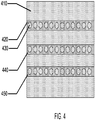
- FIG. 4 an exemplary design of three conductive traces 420, 440, and 450 on a three-dimensional surface 410 is illustrated.
- the conductive traces can be formed such that there are missing portions, circular regions 430, within the conductive traces 420, 440, and 450.
- An additive process can be used to form the conductive traces 420, 440, and 450 so that the circular regions 430 are screened out of the process.
- a subtractive process can be used to form the conductive traces 420, 440, and 450 so that the circular regions 430 are removed or etched.
- the edge of the circular regions 430 may not be vertical and instead be, for example, undercut or retrograde. Isotropic etch chemistry, especially where the conductive traces 420, 440, and 450 are formed from a stack of different metallurgies, may result in a ledge protruding over the rest of the edge profile. Where the conductive trace material is applied by a printer, the subsequent material may be flowed under the ledge and can result in a better adherence. Regardless, many different designs of both protrusions and depressions may be operant to improve adhesion characteristics of the conductive traces 420, 440, and 450.
- different metallurgies may be required where the conductive traces 420, 440, and 450 are being used to form anodes and cathodes, which require different electrochemical potentials. Such different metallurgies ensure electrochemical compatibility of the conductive traces with the attached electrode materials.
- Various choices for the types of materials that make up the anode and cathode traces may include noble metals such as silver and gold, and other metals including zinc, nickel, aluminum, titanium and/or the conductive epoxies which may include silver, gold and/or copper flakes.
- an exemplary method 500 for forming energization elements on three-dimensional surfaces is disclosed.
- a substrate having a three-dimensional surface upon which various materials will be deposited to form an energization element is received (step 502).
- the substrate may be received from another source or third-party, whereas in other embodiments the substrate may be formed by, for example, molding.
- the three-dimensional surface is roughened (step 504).
- the three-dimensional surface can be roughened by, for example, physically abrading the surface, gas phase etching, and/or liquid phase etching.
- a roughened surface may have desirable adhesion characteristics due both to the altered surface chemistry and/or also to the increased physical surface area.
- this step may be bypassed since the three-dimensional surface can be roughened during the substrate molding by providing roughened mold tooling where injection molding or cast molding can be used to form the substrates, or if the material of the substrate has acceptable adhesion characteristics.
- the coating can optionally be coated on the three-dimensional surface (step 506).
- the three-dimensional surface There may be numerous advantages for coating the three-dimensional surface, such as, for example, wettability, mechanical integrity, adhesion, and functionalizing the three-dimensional surface with active groups.
- conductive traces are defined on the three-dimensional surface (step 508).
- Numerous methods can be used to define the conductive traces, such as, for example, screen printing, shadow mask deposition, photolithography subtractive etch, or direct ablation for subtractive etch processing.
- the conductive traces can be printed on the three-dimensional surface using conductive pastes formed from adhesives and metal flake mixtures.
- silver conductor conductive traces may be defined on the three-dimensional surface using a NscryptTM printing unit, an EFD type tip and a silver based paste, such as Du Pont 5025.
- the energization elements can be formed on conductive traces.
- An anode can be deposited on a subset of the conductive traces (step 510).
- the anode chemical mixture can partially or completely cover the subset of the conductive traces.
- the anode can be deposited by masking techniques or other additive techniques, subtractive techniques, growing techniques, or plating techniques such as electroplating.
- a zinc based formulation may be deposited to define the anode.
- Numerous chemical mixtures and formulations can be deposited to define the anode.
- Table 1 provides an exemplary formulation.
- a cathode can be deposited on another subset of the conductive traces (step 512).
- the cathode chemical mixture can partially or completely cover the other subset of the conductive traces.
- the cathode can be deposited by masking techniques or other additive techniques, subtractive techniques, growing techniques, or plating techniques such as electroplating. Numerous chemical mixtures and formulations can be deposited to define the cathode. However, Table 2 provides an exemplary formulation.
- a bridge can optionally be deposited in contact with the anode and the cathode (step 514).
- the bridge chemical mixture can partially or completely cover one or more conductive traces.
- the bridge can be deposited by masking techniques or other additive techniques, subtractive techniques, growing techniques, or plating techniques such as electroplating. Numerous chemical mixtures and formulations can be deposited to define the bridge. However, Table 3 provides an exemplary formulation.
- FIG. 5 illustrates that the anode is deposited before the cathode
- the anode and the cathode can be deposited in any order.
- the cathode can be deposited before the anode.
- FIG. 5 illustrates that the bridge is deposited following deposition of the anode and the cathode.
- the bridge can first be deposited between and/or partially on the conductive traces before the deposition of the anode and the cathode to provide for better adhesion and to isolate the anode from the cathode, particularly if the chemical mixture being printed is prone to spreading.
- An electrolyte is then deposited on at least the anode and the cathode (step 516).
- the electrolyte can be in a liquid, gelatinous, or polymeric form.
- the anode, the cathode, and the electrolyte can then be encapsulated (step 518).
- the encapsulation seals the energization elements from other components, if any, on the three-dimensional surface.
- the encapsulation may be a single layer encapsulation or a double layer encapsulation, as described above.
- the outermost layer of encapsulating material can be biocompatible so that the energization element can be embedded in biocompatible devices.
- steps 516 and 518 can be reversed, such that encapsulation can be performed and followed by injection of a liquid electrolyte through the encapsulating material or through a defined filling feature formed into the encapsulating material.
- the region in the encapsulating material that the filling occurred through may also be sealed.
- the liquid electrolyte can fill a majority, such as, for example, 80% or more, of the space defined by the encapsulating material.
- the substrate may optionally be removed to separate the energization element (step 520). If the energization element is to be embedded in a biocompatible device that is not part of the substrate, the biocompatible energization element can be separated and embedded in the biocompatible device. In some embodiments, exposed regions of the conductive traces that are not encapsulated can be used as interconnections to the biocompatible energization element. For example, an integrated circuit to control the various functions of the biocompatible device can be connected to the exposed conductive traces only when a triggering event occurs so that there is minimal draw on the energization element until its energy is needed.
- the biocompatible devices can be, for example, implantable electronic devices, such as pacemakers and micro-energy harvesters, electronic pills for monitoring and/or testing a biological function, surgical devices with active components, ophthalmic devices, microsized pumps, defibrillators, stents, neural interfaces, medicament dispersal devices, or the like.
- implantable electronic devices such as pacemakers and micro-energy harvesters
- electronic pills for monitoring and/or testing a biological function
- surgical devices with active components ophthalmic devices, microsized pumps, defibrillators, stents, neural interfaces, medicament dispersal devices, or the like.
- three-dimensional biocompatible energization element can be rechargeable.
- an inductive coil can also be fabricated on the three-dimensional surface. The inductive coil could then be energized with a radio-frequency ("RF") fob.
- the inductive coil can be connected to the three-dimensional biocompatible energization element to recharge the energization element when RF is applied to the inductive coil.
- photodiodes can also be fabricated on the three-dimensional surface and connected to the three-dimensional biocompatible energization element. When exposed to light or photons, the photodiodes will produce electrons to recharge the energization element.
Landscapes
- Chemical & Material Sciences (AREA)
- Chemical Kinetics & Catalysis (AREA)
- Electrochemistry (AREA)
- General Chemical & Material Sciences (AREA)
- Engineering & Computer Science (AREA)
- Manufacturing & Machinery (AREA)
- Battery Electrode And Active Subsutance (AREA)
- Prostheses (AREA)
- Electrotherapy Devices (AREA)
- Materials For Medical Uses (AREA)
- Measurement And Recording Of Electrical Phenomena And Electrical Characteristics Of The Living Body (AREA)
- Primary Cells (AREA)
Claims (13)
- Verfahren zur Herstellung dreidimensionaler biokompatibler Energieversorgungselemente, wobei das Verfahren umfasst:Erhalten eines Substrats, das aus einem isolierenden Material besteht, wobei das Substrat eine dreidimensionale Oberfläche aufweist, wobei die dreidimensionale Oberfläche eine gekrümmte Oberfläche ist;Aufrauen wenigstens eines Teils der dreidimensionalen Oberfläche;anschließend Bilden von zwei oder mehr leitfähigen Bahnen auf der dreidimensionalen Oberfläche; anschließendAufbringen einer chemischen Anodenformulierung auf wenigstens einem Teil einer der leitfähigen Bahnen, um eine Anode zu bilden;Aufbringen einer chemischen Kathodenformulierung auf wenigstens einem Teil einer anderen der leitfähigen Bahnen, um eine Kathode zu bilden; anschließendAufbringen eines Elektrolyten auf wenigstens einem Teil der Anode und der Kathode; undVerkapseln der Anode, der Kathode und des Elektrolyten unter Verwendung eines biokompatiblen Materials, um ein dreidimensionales biokompatibles Energieversorgungselement zu bilden.
- Verfahren gemäß Anspruch 1, ferner umfassend das Beschichten wenigstens eines Teils der dreidimensionalen Oberfläche mit einer Beschichtung.
- Verfahren gemäß einem der vorstehenden Ansprüche, ferner umfassend das Aufbringen einer chemischen Brückenformulierung in Kontakt mit der Anode und der Kathode.
- Verfahren gemäß einem der vorstehenden Ansprüche, ferner umfassend das Entfernen des Substrats zum Abtrennen des dreidimensionalen biokompatiblen Energieversorgungselements.
- Verfahren gemäß einem der vorstehenden Ansprüche, wobei das Bilden der zwei oder mehr leitfähigen Bahnen auf der dreidimensionalen Oberfläche das Aufbringen einer leitfähigen chemischen Formulierung auf der dreidimensionalen Oberfläche umfasst.
- Verfahren gemäß einem der vorstehenden Ansprüche, wobei der Elektrolyt ein Gel ist.
- Verfahren gemäß einem der vorstehenden Ansprüche, ferner umfassend Verkapseln der Anode, der Kathode und des Elektrolyten unter Verwendung eines ersten Verkapselungsmaterials, wobei das Verkapseln der Anode, der Kathode und des Elektrolyten unter Verwendung des biokompatiblen Materials zum Bilden des dreidimensionalen biokompatiblen Energieversorgungselements das Verkapseln des ersten Verkapselungsmaterials unter Verwendung des biokompatiblen Materials zum Bilden des dreidimensionalen biokompatiblen Energieversorgungselements umfasst.
- Verfahren gemäß einem der vorstehenden Ansprüche, wobei die leitfähigen Bahnen Metallpartikel enthalten.
- Dreidimensionales biokompatibles Energieversorgungselement, umfassend:ein Substrat, das aus einem isolierenden Material besteht, wobei das Substrat eine dreidimensionale Oberfläche aufweist, wobei die dreidimensionale Oberfläche eine gekrümmte Oberfläche ist;wobei wenigstens ein Teil der dreidimensionalen Oberfläche aufgeraut worden ist;zwei oder mehr leitfähige Bahnen auf der dreidimensionalen Oberfläche;eine Anode, hergestellt aus einer chemischen Anodenformulierung auf wenigstens einem Teil einer der leitfähigen Bahnen;eine Kathode, hergestellt aus einer chemischen Kathodenformulierung auf wenigstens einem Teil einer anderen der leitfähigen Bahnen;einen Elektrolyten auf wenigstens einem Teil der Anode und der Kathode; undein biokompatibles Verkapselungsmaterial über der Anode, der Kathode und dem Elektrolyten.
- Energieversorgungselement gemäß Anspruch 9, ferner umfassend eine Beschichtung auf einem Teil der dreidimensionalen Oberfläche.
- Energieversorgungselement gemäß einem der Ansprüche 9 bis 10, ferner umfassend eine Brücke, die aus einer chemischen Brückenformulierung hergestellt ist, in Kontakt mit der Anode und der Kathode.
- Verfahren gemäß einem der Ansprüche 1 bis 8 oder Energieversorgungselement gemäß einem der Ansprüche 9 bis 11, wobei das biokompatible Material oder Verkapselungsmaterial Alginate, Parylene, Polyacrylnitrile, Polyethylenglycole, Polypyrrole, derivatisierte Cellulosen, Polysulfone oder Polyamide umfasst.
- Verfahren gemäß einem der Ansprüche 1 bis 8 und 12 oder Energieversorgungselement gemäß einem der Ansprüche 9 bis 11, wobei die chemische Anodenformulierung umfasst:a) Zink; oderb) ein erstes Metall, wobei die chemische Kathodenformulierung ein zweites Metall umfasst, wobei das zweite Metall von dem ersten Metall verschieden ist.
Applications Claiming Priority (1)
| Application Number | Priority Date | Filing Date | Title |
|---|---|---|---|
| US13/839,144 US9406969B2 (en) | 2013-03-15 | 2013-03-15 | Methods and apparatus to form three-dimensional biocompatible energization elements |
Publications (2)
| Publication Number | Publication Date |
|---|---|
| EP2779272A1 EP2779272A1 (de) | 2014-09-17 |
| EP2779272B1 true EP2779272B1 (de) | 2020-04-22 |
Family
ID=50280240
Family Applications (1)
| Application Number | Title | Priority Date | Filing Date |
|---|---|---|---|
| EP14160054.4A Active EP2779272B1 (de) | 2013-03-15 | 2014-03-14 | Dreidimensionales biokompatibles energieversorgungselement und methode zu dessen herstellung |
Country Status (12)
| Country | Link |
|---|---|
| US (1) | US9406969B2 (de) |
| EP (1) | EP2779272B1 (de) |
| JP (1) | JP6430132B2 (de) |
| KR (1) | KR20140113533A (de) |
| CN (1) | CN104051775B (de) |
| BR (1) | BR102014006316A2 (de) |
| CA (1) | CA2846744A1 (de) |
| HK (1) | HK1202188A1 (de) |
| IL (1) | IL231371A0 (de) |
| RU (1) | RU2628336C2 (de) |
| SG (1) | SG10201400548XA (de) |
| TW (1) | TWI600196B (de) |
Families Citing this family (41)
| Publication number | Priority date | Publication date | Assignee | Title |
|---|---|---|---|---|
| US9475709B2 (en) | 2010-08-25 | 2016-10-25 | Lockheed Martin Corporation | Perforated graphene deionization or desalination |
| US10451897B2 (en) | 2011-03-18 | 2019-10-22 | Johnson & Johnson Vision Care, Inc. | Components with multiple energization elements for biomedical devices |
| US8857983B2 (en) | 2012-01-26 | 2014-10-14 | Johnson & Johnson Vision Care, Inc. | Ophthalmic lens assembly having an integrated antenna structure |
| US9610546B2 (en) | 2014-03-12 | 2017-04-04 | Lockheed Martin Corporation | Separation membranes formed from perforated graphene and methods for use thereof |
| US9834809B2 (en) | 2014-02-28 | 2017-12-05 | Lockheed Martin Corporation | Syringe for obtaining nano-sized materials for selective assays and related methods of use |
| US9744617B2 (en) | 2014-01-31 | 2017-08-29 | Lockheed Martin Corporation | Methods for perforating multi-layer graphene through ion bombardment |
| US9844757B2 (en) | 2014-03-12 | 2017-12-19 | Lockheed Martin Corporation | Separation membranes formed from perforated graphene and methods for use thereof |
| US10653824B2 (en) | 2012-05-25 | 2020-05-19 | Lockheed Martin Corporation | Two-dimensional materials and uses thereof |
| US10376845B2 (en) | 2016-04-14 | 2019-08-13 | Lockheed Martin Corporation | Membranes with tunable selectivity |
| TW201504140A (zh) | 2013-03-12 | 2015-02-01 | Lockheed Corp | 形成具有均勻孔尺寸之多孔石墨烯之方法 |
| US9572918B2 (en) | 2013-06-21 | 2017-02-21 | Lockheed Martin Corporation | Graphene-based filter for isolating a substance from blood |
| CN106029596A (zh) | 2014-01-31 | 2016-10-12 | 洛克希德马丁公司 | 采用多孔非牺牲性支撑层的二维材料形成复合结构的方法 |
| CN105940479A (zh) | 2014-01-31 | 2016-09-14 | 洛克希德马丁公司 | 使用宽离子场穿孔二维材料 |
| US10361405B2 (en) * | 2014-08-21 | 2019-07-23 | Johnson & Johnson Vision Care, Inc. | Biomedical energization elements with polymer electrolytes |
| US10627651B2 (en) | 2014-08-21 | 2020-04-21 | Johnson & Johnson Vision Care, Inc. | Methods and apparatus to form biocompatible energization primary elements for biomedical devices with electroless sealing layers |
| US9383593B2 (en) * | 2014-08-21 | 2016-07-05 | Johnson & Johnson Vision Care, Inc. | Methods to form biocompatible energization elements for biomedical devices comprising laminates and placed separators |
| US20160056508A1 (en) * | 2014-08-21 | 2016-02-25 | Johnson & Johnson Vision Care, Inc. | Electrolyte formulations for use in biocompatible energization elements |
| US9923177B2 (en) | 2014-08-21 | 2018-03-20 | Johnson & Johnson Vision Care, Inc. | Biocompatibility of biomedical energization elements |
| US9577259B2 (en) | 2014-08-21 | 2017-02-21 | Johnson & Johnson Vision Care, Inc. | Cathode mixture for use in a biocompatible battery |
| US10381687B2 (en) | 2014-08-21 | 2019-08-13 | Johnson & Johnson Vision Care, Inc. | Methods of forming biocompatible rechargable energization elements for biomedical devices |
| US9715130B2 (en) | 2014-08-21 | 2017-07-25 | Johnson & Johnson Vision Care, Inc. | Methods and apparatus to form separators for biocompatible energization elements for biomedical devices |
| US9599842B2 (en) | 2014-08-21 | 2017-03-21 | Johnson & Johnson Vision Care, Inc. | Device and methods for sealing and encapsulation for biocompatible energization elements |
| US9941547B2 (en) | 2014-08-21 | 2018-04-10 | Johnson & Johnson Vision Care, Inc. | Biomedical energization elements with polymer electrolytes and cavity structures |
| US9793536B2 (en) | 2014-08-21 | 2017-10-17 | Johnson & Johnson Vision Care, Inc. | Pellet form cathode for use in a biocompatible battery |
| US10361404B2 (en) | 2014-08-21 | 2019-07-23 | Johnson & Johnson Vision Care, Inc. | Anodes for use in biocompatible energization elements |
| US9899700B2 (en) | 2014-08-21 | 2018-02-20 | Johnson & Johnson Vision Care, Inc. | Methods to form biocompatible energization elements for biomedical devices comprising laminates and deposited separators |
| JP2017534311A (ja) | 2014-09-02 | 2017-11-24 | ロッキード・マーチン・コーポレーション | 二次元膜材料をベースとする血液透析膜および血液濾過膜、ならびにそれを用いた方法 |
| KR101988874B1 (ko) | 2014-10-23 | 2019-06-14 | 페이스북, 인크. | 3차원으로 제조되는 구조체용 기반-구조 전도성 트레이스 및 인터커넥트의 제조 |
| JP6629314B2 (ja) | 2014-10-23 | 2020-01-15 | フェイスブック,インク. | モジュール式で組み立てられる三次元印刷された電子基板を生成するための方法 |
| JP2018528144A (ja) | 2015-08-05 | 2018-09-27 | ロッキード・マーチン・コーポレーション | グラフェン系材料の穿孔可能なシート |
| WO2017023377A1 (en) | 2015-08-06 | 2017-02-09 | Lockheed Martin Corporation | Nanoparticle modification and perforation of graphene |
| US10345620B2 (en) | 2016-02-18 | 2019-07-09 | Johnson & Johnson Vision Care, Inc. | Methods and apparatus to form biocompatible energization elements incorporating fuel cells for biomedical devices |
| KR20180133430A (ko) | 2016-04-14 | 2018-12-14 | 록히드 마틴 코포레이션 | 결함 형성 또는 힐링의 인 시츄 모니터링 및 제어를 위한 방법 |
| WO2017180134A1 (en) | 2016-04-14 | 2017-10-19 | Lockheed Martin Corporation | Methods for in vivo and in vitro use of graphene and other two-dimensional materials |
| EP3442697A4 (de) | 2016-04-14 | 2020-03-18 | Lockheed Martin Corporation | Selektive grenzflächenminderung von graphendefekten |
| EP3442786A4 (de) | 2016-04-14 | 2020-03-18 | Lockheed Martin Corporation | Zweidimensionale membranstrukturen mit strömungskanälen |
| EP3442739A4 (de) | 2016-04-14 | 2020-03-04 | Lockheed Martin Corporation | Verfahren zur behandlung von graphenfolien für grossflächigen transfer mittels free-float-verfahren |
| US20180104921A1 (en) * | 2016-10-17 | 2018-04-19 | Johnson & Johnson Vision Care, Inc. | Biomedical device batteries with electrodeposited cathodes |
| US10950912B2 (en) | 2017-06-14 | 2021-03-16 | Milwaukee Electric Tool Corporation | Arrangements for inhibiting intrusion into battery pack electrical components |
| EP4147292A4 (de) * | 2020-05-07 | 2025-03-19 | Zelos Energy Ltd. | Raumkonfigurierbare batteriestrukturen für elektrodenanordnungen mit ionenaustauschmaterialien |
| WO2023112193A1 (ja) * | 2021-12-15 | 2023-06-22 | 日本電信電話株式会社 | バイオデバイスの作製方法 |
Family Cites Families (18)
| Publication number | Priority date | Publication date | Assignee | Title |
|---|---|---|---|---|
| US5561004A (en) | 1994-02-25 | 1996-10-01 | Bates; John B. | Packaging material for thin film lithium batteries |
| US6087549A (en) * | 1997-09-22 | 2000-07-11 | Argentum International | Multilayer laminate wound dressing |
| US6610440B1 (en) * | 1998-03-10 | 2003-08-26 | Bipolar Technologies, Inc | Microscopic batteries for MEMS systems |
| US6379835B1 (en) * | 1999-01-12 | 2002-04-30 | Morgan Adhesives Company | Method of making a thin film battery |
| RU2165117C1 (ru) * | 1999-12-21 | 2001-04-10 | Гудович Анатолий Петрович | Устройство для получения электрической энергии |
| WO2001073883A2 (en) * | 2000-03-24 | 2001-10-04 | Cymbet Corporation | Low-temperature fabrication of thin-film energy-storage devices |
| EP1278255A4 (de) * | 2000-04-26 | 2007-09-05 | Sanyo Electric Co | Lithium-sekundärbatterie benutzende elektrode und lithiumsekundärbatterie |
| US7457667B2 (en) * | 2004-02-19 | 2008-11-25 | Silverleaf Medical Products, Inc. | Current producing surface for a wound dressing |
| FR2916577B1 (fr) * | 2007-05-25 | 2009-11-27 | Commissariat Energie Atomique | Verre organique electrolytique, son procede de fabrication et dispositif le comprenant. |
| US8574754B2 (en) * | 2007-12-19 | 2013-11-05 | Blue Spark Technologies, Inc. | High current thin electrochemical cell and methods of making the same |
| US8815450B1 (en) * | 2008-01-28 | 2014-08-26 | Oak Ridge Micro-Energy, Inc. | Low voltage thin film batteries |
| US9296158B2 (en) * | 2008-09-22 | 2016-03-29 | Johnson & Johnson Vision Care, Inc. | Binder of energized components in an ophthalmic lens |
| US20100076553A1 (en) * | 2008-09-22 | 2010-03-25 | Pugh Randall B | Energized ophthalmic lens |
| MX2012002732A (es) * | 2009-09-03 | 2012-10-09 | Molecular Nanosystems Inc | Metodos y sistemas para producir electrodos que tienen al menos un grandiente funcional en los mismos y los dispositivos resultantes de los mismos. |
| KR101051977B1 (ko) * | 2009-10-22 | 2011-07-26 | 주식회사로케트전기 | 박형전지를 구비하는 장치 및 이온토포레시스 패치 |
| US8744567B2 (en) * | 2009-11-13 | 2014-06-03 | Johnson & Johnson Consumer Companies, Inc. | Galvanic skin treatment device |
| KR101953399B1 (ko) * | 2010-09-13 | 2019-05-22 | 더 리전츠 오브 더 유니버시티 오브 캘리포니아 | 이온성 겔 전해질, 에너지 저장 장치, 및 이의 제조 방법 |
| US9698129B2 (en) | 2011-03-18 | 2017-07-04 | Johnson & Johnson Vision Care, Inc. | Stacked integrated component devices with energization |
-
2013
- 2013-03-15 US US13/839,144 patent/US9406969B2/en active Active
-
2014
- 2014-03-06 IL IL231371A patent/IL231371A0/en unknown
- 2014-03-11 SG SG10201400548XA patent/SG10201400548XA/en unknown
- 2014-03-13 TW TW103108923A patent/TWI600196B/zh not_active IP Right Cessation
- 2014-03-14 CN CN201410095319.7A patent/CN104051775B/zh active Active
- 2014-03-14 JP JP2014051346A patent/JP6430132B2/ja active Active
- 2014-03-14 RU RU2014109972A patent/RU2628336C2/ru not_active IP Right Cessation
- 2014-03-14 CA CA2846744A patent/CA2846744A1/en not_active Abandoned
- 2014-03-14 KR KR1020140030293A patent/KR20140113533A/ko not_active Ceased
- 2014-03-14 EP EP14160054.4A patent/EP2779272B1/de active Active
- 2014-03-17 BR BRBR102014006316-1A patent/BR102014006316A2/pt not_active IP Right Cessation
-
2015
- 2015-03-16 HK HK15102612.7A patent/HK1202188A1/en unknown
Non-Patent Citations (1)
| Title |
|---|
| None * |
Also Published As
| Publication number | Publication date |
|---|---|
| SG10201400548XA (en) | 2014-10-30 |
| JP6430132B2 (ja) | 2018-11-28 |
| JP2014180567A (ja) | 2014-09-29 |
| TW201528586A (zh) | 2015-07-16 |
| KR20140113533A (ko) | 2014-09-24 |
| US9406969B2 (en) | 2016-08-02 |
| CN104051775B (zh) | 2018-01-02 |
| RU2014109972A (ru) | 2015-09-20 |
| EP2779272A1 (de) | 2014-09-17 |
| US20140272522A1 (en) | 2014-09-18 |
| HK1202188A1 (en) | 2015-09-18 |
| IL231371A0 (en) | 2014-08-31 |
| CA2846744A1 (en) | 2014-09-15 |
| TWI600196B (zh) | 2017-09-21 |
| CN104051775A (zh) | 2014-09-17 |
| BR102014006316A2 (pt) | 2014-12-09 |
| RU2628336C2 (ru) | 2017-08-16 |
Similar Documents
| Publication | Publication Date | Title |
|---|---|---|
| EP2779272B1 (de) | Dreidimensionales biokompatibles energieversorgungselement und methode zu dessen herstellung | |
| AU2014201529A1 (en) | Methods and apparatus to form three-dimensional biocompatible energization elements | |
| US10558062B2 (en) | Methods and apparatus to form biocompatible energization primary elements for biomedical device | |
| US10381687B2 (en) | Methods of forming biocompatible rechargable energization elements for biomedical devices | |
| EP2988358B1 (de) | Verfahren zur herstellung biokompatibler erregungselemente für biomedizinische vorrichtungen mit laminaten und aufgebrachten separatoren | |
| CN104582942A (zh) | 用于在眼科装置上形成印刷电池组的方法和设备 | |
| US10627651B2 (en) | Methods and apparatus to form biocompatible energization primary elements for biomedical devices with electroless sealing layers | |
| EP3419078A1 (de) | Verfahren und vorrichtung zum bilden von biokompatiblen energiebeaufschlagenden primärelementen für biomedizinische vorrichtungen mit stromlosen dichtungsschichten | |
| EP3419077A1 (de) | Biokompatible wiederaufladbarer erregungselemente für biomedizinische vorrichtungen mit stromlosen abdichtungsschichten | |
| US20200212402A1 (en) | Biocompatible rechargable energization elements for biomedical devices with electroless sealing layers | |
| HK40000263A (en) | Methods and apparatus to form biocompatible energization primary elements for biomedical devices with electroless sealing layers | |
| HK40000264A (en) | Biocompatible rechargable energization elements for biomedical devices with electroless sealing layers | |
| HK1223739B (en) | Biocompatible primary batteries for biomedical devices | |
| HK1219807B (en) | Methods to form biocompatible energization elements for biomedical devices comprising laminates and deposited separators |
Legal Events
| Date | Code | Title | Description |
|---|---|---|---|
| 17P | Request for examination filed |
Effective date: 20140314 |
|
| AK | Designated contracting states |
Kind code of ref document: A1 Designated state(s): AL AT BE BG CH CY CZ DE DK EE ES FI FR GB GR HR HU IE IS IT LI LT LU LV MC MK MT NL NO PL PT RO RS SE SI SK SM TR |
|
| AX | Request for extension of the european patent |
Extension state: BA ME |
|
| PUAI | Public reference made under article 153(3) epc to a published international application that has entered the european phase |
Free format text: ORIGINAL CODE: 0009012 |
|
| R17P | Request for examination filed (corrected) |
Effective date: 20150313 |
|
| RBV | Designated contracting states (corrected) |
Designated state(s): AL AT BE BG CH CY CZ DE DK EE ES FI FR GB GR HR HU IE IS IT LI LT LU LV MC MK MT NL NO PL PT RO RS SE SI SK SM TR |
|
| RIN1 | Information on inventor provided before grant (corrected) |
Inventor name: PUGH, RANDALL B. Inventor name: FLITSCH, FREDERICK A. Inventor name: OTTS, DANIEL B. Inventor name: HARDY, KATHERINE |
|
| REG | Reference to a national code |
Ref country code: HK Ref legal event code: DE Ref document number: 1202188 Country of ref document: HK |
|
| 17Q | First examination report despatched |
Effective date: 20160216 |
|
| STAA | Information on the status of an ep patent application or granted ep patent |
Free format text: STATUS: EXAMINATION IS IN PROGRESS |
|
| GRAP | Despatch of communication of intention to grant a patent |
Free format text: ORIGINAL CODE: EPIDOSNIGR1 |
|
| STAA | Information on the status of an ep patent application or granted ep patent |
Free format text: STATUS: GRANT OF PATENT IS INTENDED |
|
| RIC1 | Information provided on ipc code assigned before grant |
Ipc: H01M 6/22 20060101ALI20190930BHEP Ipc: H01M 4/04 20060101ALI20190930BHEP Ipc: H01M 4/26 20060101ALI20190930BHEP Ipc: H01M 6/40 20060101ALI20190930BHEP Ipc: H01M 4/42 20060101ALN20190930BHEP Ipc: H01M 4/66 20060101ALN20190930BHEP Ipc: H01M 4/08 20060101ALI20190930BHEP Ipc: H01M 6/06 20060101ALN20190930BHEP Ipc: H01M 4/38 20060101ALI20190930BHEP Ipc: H01M 4/24 20060101ALI20190930BHEP Ipc: H01M 2/02 20060101AFI20190930BHEP |
|
| INTG | Intention to grant announced |
Effective date: 20191023 |
|
| GRAS | Grant fee paid |
Free format text: ORIGINAL CODE: EPIDOSNIGR3 |
|
| GRAJ | Information related to disapproval of communication of intention to grant by the applicant or resumption of examination proceedings by the epo deleted |
Free format text: ORIGINAL CODE: EPIDOSDIGR1 |
|
| GRAL | Information related to payment of fee for publishing/printing deleted |
Free format text: ORIGINAL CODE: EPIDOSDIGR3 |
|
| STAA | Information on the status of an ep patent application or granted ep patent |
Free format text: STATUS: EXAMINATION IS IN PROGRESS |
|
| GRAR | Information related to intention to grant a patent recorded |
Free format text: ORIGINAL CODE: EPIDOSNIGR71 |
|
| STAA | Information on the status of an ep patent application or granted ep patent |
Free format text: STATUS: GRANT OF PATENT IS INTENDED |
|
| GRAA | (expected) grant |
Free format text: ORIGINAL CODE: 0009210 |
|
| STAA | Information on the status of an ep patent application or granted ep patent |
Free format text: STATUS: THE PATENT HAS BEEN GRANTED |
|
| INTC | Intention to grant announced (deleted) | ||
| RIC1 | Information provided on ipc code assigned before grant |
Ipc: H01M 4/24 20060101ALI20200306BHEP Ipc: H01M 2/02 20060101AFI20200306BHEP Ipc: H01M 6/40 20060101ALI20200306BHEP Ipc: H01M 4/42 20060101ALN20200306BHEP Ipc: H01M 4/26 20060101ALI20200306BHEP Ipc: H01M 4/08 20060101ALI20200306BHEP Ipc: H01M 4/04 20060101ALI20200306BHEP Ipc: H01M 4/38 20060101ALI20200306BHEP Ipc: H01M 4/66 20060101ALN20200306BHEP Ipc: H01M 6/06 20060101ALN20200306BHEP Ipc: H01M 6/22 20060101ALI20200306BHEP |
|
| AK | Designated contracting states |
Kind code of ref document: B1 Designated state(s): AL AT BE BG CH CY CZ DE DK EE ES FI FR GB GR HR HU IE IS IT LI LT LU LV MC MK MT NL NO PL PT RO RS SE SI SK SM TR |
|
| INTG | Intention to grant announced |
Effective date: 20200317 |
|
| REG | Reference to a national code |
Ref country code: GB Ref legal event code: FG4D |
|
| REG | Reference to a national code |
Ref country code: CH Ref legal event code: EP |
|
| REG | Reference to a national code |
Ref country code: DE Ref legal event code: R096 Ref document number: 602014064013 Country of ref document: DE |
|
| REG | Reference to a national code |
Ref country code: IE Ref legal event code: FG4D |
|
| REG | Reference to a national code |
Ref country code: AT Ref legal event code: REF Ref document number: 1261320 Country of ref document: AT Kind code of ref document: T Effective date: 20200515 |
|
| REG | Reference to a national code |
Ref country code: LT Ref legal event code: MG4D |
|
| REG | Reference to a national code |
Ref country code: NL Ref legal event code: MP Effective date: 20200422 |
|
| PG25 | Lapsed in a contracting state [announced via postgrant information from national office to epo] |
Ref country code: IS Free format text: LAPSE BECAUSE OF FAILURE TO SUBMIT A TRANSLATION OF THE DESCRIPTION OR TO PAY THE FEE WITHIN THE PRESCRIBED TIME-LIMIT Effective date: 20200822 Ref country code: SE Free format text: LAPSE BECAUSE OF FAILURE TO SUBMIT A TRANSLATION OF THE DESCRIPTION OR TO PAY THE FEE WITHIN THE PRESCRIBED TIME-LIMIT Effective date: 20200422 Ref country code: GR Free format text: LAPSE BECAUSE OF FAILURE TO SUBMIT A TRANSLATION OF THE DESCRIPTION OR TO PAY THE FEE WITHIN THE PRESCRIBED TIME-LIMIT Effective date: 20200723 Ref country code: NO Free format text: LAPSE BECAUSE OF FAILURE TO SUBMIT A TRANSLATION OF THE DESCRIPTION OR TO PAY THE FEE WITHIN THE PRESCRIBED TIME-LIMIT Effective date: 20200722 Ref country code: FI Free format text: LAPSE BECAUSE OF FAILURE TO SUBMIT A TRANSLATION OF THE DESCRIPTION OR TO PAY THE FEE WITHIN THE PRESCRIBED TIME-LIMIT Effective date: 20200422 Ref country code: LT Free format text: LAPSE BECAUSE OF FAILURE TO SUBMIT A TRANSLATION OF THE DESCRIPTION OR TO PAY THE FEE WITHIN THE PRESCRIBED TIME-LIMIT Effective date: 20200422 Ref country code: PT Free format text: LAPSE BECAUSE OF FAILURE TO SUBMIT A TRANSLATION OF THE DESCRIPTION OR TO PAY THE FEE WITHIN THE PRESCRIBED TIME-LIMIT Effective date: 20200824 Ref country code: NL Free format text: LAPSE BECAUSE OF FAILURE TO SUBMIT A TRANSLATION OF THE DESCRIPTION OR TO PAY THE FEE WITHIN THE PRESCRIBED TIME-LIMIT Effective date: 20200422 |
|
| REG | Reference to a national code |
Ref country code: AT Ref legal event code: MK05 Ref document number: 1261320 Country of ref document: AT Kind code of ref document: T Effective date: 20200422 |
|
| REG | Reference to a national code |
Ref country code: DE Ref legal event code: R079 Ref document number: 602014064013 Country of ref document: DE Free format text: PREVIOUS MAIN CLASS: H01M0002020000 Ipc: H01M0050100000 |
|
| PG25 | Lapsed in a contracting state [announced via postgrant information from national office to epo] |
Ref country code: HR Free format text: LAPSE BECAUSE OF FAILURE TO SUBMIT A TRANSLATION OF THE DESCRIPTION OR TO PAY THE FEE WITHIN THE PRESCRIBED TIME-LIMIT Effective date: 20200422 Ref country code: RS Free format text: LAPSE BECAUSE OF FAILURE TO SUBMIT A TRANSLATION OF THE DESCRIPTION OR TO PAY THE FEE WITHIN THE PRESCRIBED TIME-LIMIT Effective date: 20200422 Ref country code: LV Free format text: LAPSE BECAUSE OF FAILURE TO SUBMIT A TRANSLATION OF THE DESCRIPTION OR TO PAY THE FEE WITHIN THE PRESCRIBED TIME-LIMIT Effective date: 20200422 Ref country code: BG Free format text: LAPSE BECAUSE OF FAILURE TO SUBMIT A TRANSLATION OF THE DESCRIPTION OR TO PAY THE FEE WITHIN THE PRESCRIBED TIME-LIMIT Effective date: 20200722 |
|
| PG25 | Lapsed in a contracting state [announced via postgrant information from national office to epo] |
Ref country code: AL Free format text: LAPSE BECAUSE OF FAILURE TO SUBMIT A TRANSLATION OF THE DESCRIPTION OR TO PAY THE FEE WITHIN THE PRESCRIBED TIME-LIMIT Effective date: 20200422 |
|
| REG | Reference to a national code |
Ref country code: DE Ref legal event code: R097 Ref document number: 602014064013 Country of ref document: DE |
|
| PG25 | Lapsed in a contracting state [announced via postgrant information from national office to epo] |
Ref country code: IT Free format text: LAPSE BECAUSE OF FAILURE TO SUBMIT A TRANSLATION OF THE DESCRIPTION OR TO PAY THE FEE WITHIN THE PRESCRIBED TIME-LIMIT Effective date: 20200422 Ref country code: CZ Free format text: LAPSE BECAUSE OF FAILURE TO SUBMIT A TRANSLATION OF THE DESCRIPTION OR TO PAY THE FEE WITHIN THE PRESCRIBED TIME-LIMIT Effective date: 20200422 Ref country code: RO Free format text: LAPSE BECAUSE OF FAILURE TO SUBMIT A TRANSLATION OF THE DESCRIPTION OR TO PAY THE FEE WITHIN THE PRESCRIBED TIME-LIMIT Effective date: 20200422 Ref country code: ES Free format text: LAPSE BECAUSE OF FAILURE TO SUBMIT A TRANSLATION OF THE DESCRIPTION OR TO PAY THE FEE WITHIN THE PRESCRIBED TIME-LIMIT Effective date: 20200422 Ref country code: EE Free format text: LAPSE BECAUSE OF FAILURE TO SUBMIT A TRANSLATION OF THE DESCRIPTION OR TO PAY THE FEE WITHIN THE PRESCRIBED TIME-LIMIT Effective date: 20200422 Ref country code: AT Free format text: LAPSE BECAUSE OF FAILURE TO SUBMIT A TRANSLATION OF THE DESCRIPTION OR TO PAY THE FEE WITHIN THE PRESCRIBED TIME-LIMIT Effective date: 20200422 Ref country code: SM Free format text: LAPSE BECAUSE OF FAILURE TO SUBMIT A TRANSLATION OF THE DESCRIPTION OR TO PAY THE FEE WITHIN THE PRESCRIBED TIME-LIMIT Effective date: 20200422 Ref country code: DK Free format text: LAPSE BECAUSE OF FAILURE TO SUBMIT A TRANSLATION OF THE DESCRIPTION OR TO PAY THE FEE WITHIN THE PRESCRIBED TIME-LIMIT Effective date: 20200422 |
|
| PG25 | Lapsed in a contracting state [announced via postgrant information from national office to epo] |
Ref country code: PL Free format text: LAPSE BECAUSE OF FAILURE TO SUBMIT A TRANSLATION OF THE DESCRIPTION OR TO PAY THE FEE WITHIN THE PRESCRIBED TIME-LIMIT Effective date: 20200422 Ref country code: SK Free format text: LAPSE BECAUSE OF FAILURE TO SUBMIT A TRANSLATION OF THE DESCRIPTION OR TO PAY THE FEE WITHIN THE PRESCRIBED TIME-LIMIT Effective date: 20200422 |
|
| PLBE | No opposition filed within time limit |
Free format text: ORIGINAL CODE: 0009261 |
|
| STAA | Information on the status of an ep patent application or granted ep patent |
Free format text: STATUS: NO OPPOSITION FILED WITHIN TIME LIMIT |
|
| 26N | No opposition filed |
Effective date: 20210125 |
|
| PG25 | Lapsed in a contracting state [announced via postgrant information from national office to epo] |
Ref country code: SI Free format text: LAPSE BECAUSE OF FAILURE TO SUBMIT A TRANSLATION OF THE DESCRIPTION OR TO PAY THE FEE WITHIN THE PRESCRIBED TIME-LIMIT Effective date: 20200422 |
|
| REG | Reference to a national code |
Ref country code: HK Ref legal event code: WD Ref document number: 1202188 Country of ref document: HK |
|
| PG25 | Lapsed in a contracting state [announced via postgrant information from national office to epo] |
Ref country code: MC Free format text: LAPSE BECAUSE OF FAILURE TO SUBMIT A TRANSLATION OF THE DESCRIPTION OR TO PAY THE FEE WITHIN THE PRESCRIBED TIME-LIMIT Effective date: 20200422 |
|
| REG | Reference to a national code |
Ref country code: CH Ref legal event code: PL |
|
| REG | Reference to a national code |
Ref country code: BE Ref legal event code: MM Effective date: 20210331 |
|
| PG25 | Lapsed in a contracting state [announced via postgrant information from national office to epo] |
Ref country code: LU Free format text: LAPSE BECAUSE OF NON-PAYMENT OF DUE FEES Effective date: 20210314 Ref country code: LI Free format text: LAPSE BECAUSE OF NON-PAYMENT OF DUE FEES Effective date: 20210331 Ref country code: CH Free format text: LAPSE BECAUSE OF NON-PAYMENT OF DUE FEES Effective date: 20210331 Ref country code: FR Free format text: LAPSE BECAUSE OF NON-PAYMENT OF DUE FEES Effective date: 20210331 |
|
| PG25 | Lapsed in a contracting state [announced via postgrant information from national office to epo] |
Ref country code: BE Free format text: LAPSE BECAUSE OF NON-PAYMENT OF DUE FEES Effective date: 20210331 |
|
| PGFP | Annual fee paid to national office [announced via postgrant information from national office to epo] |
Ref country code: IE Payment date: 20230209 Year of fee payment: 10 |
|
| PG25 | Lapsed in a contracting state [announced via postgrant information from national office to epo] |
Ref country code: HU Free format text: LAPSE BECAUSE OF FAILURE TO SUBMIT A TRANSLATION OF THE DESCRIPTION OR TO PAY THE FEE WITHIN THE PRESCRIBED TIME-LIMIT; INVALID AB INITIO Effective date: 20140314 |
|
| PGFP | Annual fee paid to national office [announced via postgrant information from national office to epo] |
Ref country code: GB Payment date: 20230202 Year of fee payment: 10 |
|
| PG25 | Lapsed in a contracting state [announced via postgrant information from national office to epo] |
Ref country code: CY Free format text: LAPSE BECAUSE OF FAILURE TO SUBMIT A TRANSLATION OF THE DESCRIPTION OR TO PAY THE FEE WITHIN THE PRESCRIBED TIME-LIMIT Effective date: 20200422 |
|
| PG25 | Lapsed in a contracting state [announced via postgrant information from national office to epo] |
Ref country code: MK Free format text: LAPSE BECAUSE OF FAILURE TO SUBMIT A TRANSLATION OF THE DESCRIPTION OR TO PAY THE FEE WITHIN THE PRESCRIBED TIME-LIMIT Effective date: 20200422 |
|
| PG25 | Lapsed in a contracting state [announced via postgrant information from national office to epo] |
Ref country code: TR Free format text: LAPSE BECAUSE OF FAILURE TO SUBMIT A TRANSLATION OF THE DESCRIPTION OR TO PAY THE FEE WITHIN THE PRESCRIBED TIME-LIMIT Effective date: 20200422 |
|
| PG25 | Lapsed in a contracting state [announced via postgrant information from national office to epo] |
Ref country code: MT Free format text: LAPSE BECAUSE OF FAILURE TO SUBMIT A TRANSLATION OF THE DESCRIPTION OR TO PAY THE FEE WITHIN THE PRESCRIBED TIME-LIMIT Effective date: 20200422 |
|
| GBPC | Gb: european patent ceased through non-payment of renewal fee |
Effective date: 20240314 |
|
| PG25 | Lapsed in a contracting state [announced via postgrant information from national office to epo] |
Ref country code: GB Free format text: LAPSE BECAUSE OF NON-PAYMENT OF DUE FEES Effective date: 20240314 |
|
| PG25 | Lapsed in a contracting state [announced via postgrant information from national office to epo] |
Ref country code: IE Free format text: LAPSE BECAUSE OF NON-PAYMENT OF DUE FEES Effective date: 20240314 |
|
| PG25 | Lapsed in a contracting state [announced via postgrant information from national office to epo] |
Ref country code: IE Free format text: LAPSE BECAUSE OF NON-PAYMENT OF DUE FEES Effective date: 20240314 Ref country code: GB Free format text: LAPSE BECAUSE OF NON-PAYMENT OF DUE FEES Effective date: 20240314 |
|
| PGFP | Annual fee paid to national office [announced via postgrant information from national office to epo] |
Ref country code: DE Payment date: 20260204 Year of fee payment: 13 |