EP2779378A2 - Erdungsvorrichtung für elektrische Maschine und Verfahren zur dessen Montage - Google Patents
Erdungsvorrichtung für elektrische Maschine und Verfahren zur dessen Montage Download PDFInfo
- Publication number
- EP2779378A2 EP2779378A2 EP14158994.5A EP14158994A EP2779378A2 EP 2779378 A2 EP2779378 A2 EP 2779378A2 EP 14158994 A EP14158994 A EP 14158994A EP 2779378 A2 EP2779378 A2 EP 2779378A2
- Authority
- EP
- European Patent Office
- Prior art keywords
- wire core
- shaft
- electric machine
- coupled
- fibers
- Prior art date
- Legal status (The legal status is an assumption and is not a legal conclusion. Google has not performed a legal analysis and makes no representation as to the accuracy of the status listed.)
- Withdrawn
Links
- 238000000034 method Methods 0.000 title description 8
- 239000000835 fiber Substances 0.000 claims abstract description 50
- 230000008878 coupling Effects 0.000 claims description 8
- 238000010168 coupling process Methods 0.000 claims description 8
- 238000005859 coupling reaction Methods 0.000 claims description 8
- RYGMFSIKBFXOCR-UHFFFAOYSA-N Copper Chemical compound [Cu] RYGMFSIKBFXOCR-UHFFFAOYSA-N 0.000 claims description 5
- 229910052802 copper Inorganic materials 0.000 claims description 5
- 239000010949 copper Substances 0.000 claims description 5
- 229920002972 Acrylic fiber Polymers 0.000 claims description 2
- 229920000049 Carbon (fiber) Polymers 0.000 claims description 2
- 239000004917 carbon fiber Substances 0.000 claims description 2
- 239000011248 coating agent Substances 0.000 claims description 2
- 238000000576 coating method Methods 0.000 claims description 2
- 230000006870 function Effects 0.000 description 8
- 238000009434 installation Methods 0.000 description 6
- 239000000463 material Substances 0.000 description 4
- 238000004378 air conditioning Methods 0.000 description 3
- 239000004020 conductor Substances 0.000 description 3
- 238000005516 engineering process Methods 0.000 description 3
- 238000003754 machining Methods 0.000 description 3
- 239000007787 solid Substances 0.000 description 3
- 230000004927 fusion Effects 0.000 description 2
- 238000003475 lamination Methods 0.000 description 2
- 239000002184 metal Substances 0.000 description 2
- 229910052751 metal Inorganic materials 0.000 description 2
- 238000004804 winding Methods 0.000 description 2
- 229910001369 Brass Inorganic materials 0.000 description 1
- 229910000831 Steel Inorganic materials 0.000 description 1
- 230000015572 biosynthetic process Effects 0.000 description 1
- 230000000740 bleeding effect Effects 0.000 description 1
- 238000007664 blowing Methods 0.000 description 1
- 239000010951 brass Substances 0.000 description 1
- 239000002131 composite material Substances 0.000 description 1
- 238000010276 construction Methods 0.000 description 1
- 238000001816 cooling Methods 0.000 description 1
- 230000007797 corrosion Effects 0.000 description 1
- 238000005260 corrosion Methods 0.000 description 1
- 239000012530 fluid Substances 0.000 description 1
- 239000004519 grease Substances 0.000 description 1
- 238000010438 heat treatment Methods 0.000 description 1
- 150000002739 metals Chemical class 0.000 description 1
- VNWKTOKETHGBQD-UHFFFAOYSA-N methane Chemical compound C VNWKTOKETHGBQD-UHFFFAOYSA-N 0.000 description 1
- 230000000116 mitigating effect Effects 0.000 description 1
- 239000011236 particulate material Substances 0.000 description 1
- 239000013618 particulate matter Substances 0.000 description 1
- 230000002028 premature Effects 0.000 description 1
- 238000005086 pumping Methods 0.000 description 1
- 238000005057 refrigeration Methods 0.000 description 1
- 238000010079 rubber tapping Methods 0.000 description 1
- 239000010959 steel Substances 0.000 description 1
- 238000009423 ventilation Methods 0.000 description 1
Images


Classifications
-
- H—ELECTRICITY
- H02—GENERATION; CONVERSION OR DISTRIBUTION OF ELECTRIC POWER
- H02K—DYNAMO-ELECTRIC MACHINES
- H02K11/00—Structural association of dynamo-electric machines with electric components or with devices for shielding, monitoring or protection
- H02K11/40—Structural association with grounding devices
Definitions
- the field of the invention relates generally to grounding devices and, more particularly, to grounding devices for electric machines having stray electrostatic charges on a rotatable shaft.
- variable speed drives Some known electric machines such as three-phase motors are driven by variable speed drives that may induce a voltage or electrostatic charge on the motor shaft.
- Some variable speed drives utilize pulse width modulation technology to vary the speed of AC motors, which allows use of less expensive AC motors in applications where more expensive DC motors may be used.
- a drawback of the use of AC motors with variable speed drives is that higher common mode voltage (CMV) is generated by the variable speed drive, which may increase induced currents on the shaft.
- CMV common mode voltage
- the technologies include conductive bearing grease, insulating the bearings, and using various brushes made of metal or other materials to ground the shaft. Such brushes are typically mounted in rigid holders and may be expensive and require lengthy installation procedures. Moreover, the brushes are designed only for a specific size motor shaft.
- a grounding device for an electric machine having a rotatable shaft.
- the grounding device includes a wire core having a first end and a second end, and a plurality of conductive fibers coupled to the wire core and extending therefrom.
- the wire core is configured to couple to the electric machine with at least a portion of the plurality of conductive fibers contacting the shaft such that an electrostatic charge on the shaft is directed through the grounding device to ground.
- an electric machine in another aspect, includes a housing, a shaft rotatably coupled to the housing, a rotor coupled to the shaft, a stator coupled to the housing and a grounding device conductively coupled to ground through at least one of the housing and the stator.
- the grounding device includes a wire core having a first end and a second end, and a plurality of conductive fibers coupled to the wire core and extending therefrom. At least a portion of the plurality of conductive fibers contacts at least one of the shaft and the rotor such that an electrostatic charge on the shaft is directed to ground.
- a method of assembling an electric machine includes providing a housing, rotatably coupling a shaft to the housing, coupling a rotor to the shaft, coupling a stator to the housing, and coupling a grounding device to ground through at least one of the housing and the stator.
- the grounding device includes a wire core having a first end, a second end, and a plurality of conductive fibers coupled to the wire core and extending therefrom. At least a portion of the plurality of conductive fibers contacts the shaft such that an electrostatic charge on the shaft is directed through the grounding device to ground.
- Electrostatic charges may build on rotating parts of electric machines. These charges may travel through and damage bearings used to support the rotating parts of the machines. Grounding devices may be used to bleed the electrostatic charge to ground. However, known grounding devices are expensive, are not adjustable to different sized machines, and/or require extensive installation and machining of the electric machine. Set forth herein are descriptions of systems and methods for an economical and efficient grounding device that is flexible and adjustable, which enables use with varying sized electrical machines.
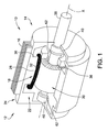
- FIG. 1 is a perspective cut-away view of an exemplary electric machine 10 that may be operated as either a generator or a motor.
- Electric machine 10 includes a first end 12, a second end 14, and a motor assembly housing 16.
- Electric machine 10 also includes a stationary assembly 18 and a rotatable assembly 20.
- Motor assembly housing 16 defines an interior 22 and an exterior 24 of machine 10 and is configured to at least partially enclose and protect stationary assembly 18 and rotatable assembly 20.
- Stationary assembly 18 includes a stator core 28, which includes a plurality of teeth 30 and a plurality of windings 32 wound around stator teeth 30.
- stationary assembly 18 is a three-phase stator assembly and stator core 28 is formed from a stack of laminations made of highly magnetically permeable material.
- stationary assembly 18 is solid and/or is a single phase stator assembly.
- Stationary assembly 18 may be a round, segmented, or roll-up type stator construction and windings 32 are wound on stator core 28 in any suitable manner that enables machine 10 to function as described herein.
- Rotatable assembly includes a permanent magnet rotor core 36 and a shaft 38 supported by bearings 40.
- rotor core 36 is formed from a stack of laminations made of magnetically permeable material.
- rotor core 36 is a solid core.
- Rotor core 36 is substantially received in a central bore of stator core 28 for rotation along an axis of rotation X.
- FIG. 1 illustrates rotor core 36 and stator core 28 as solid for simplicity. While FIG. 1 is an illustration of a three-phase electric machine, the methods and apparatus described herein may be included within machines having any number of phases.
- electric motor 10 is coupled to a fan or centrifugal blower (not shown) for moving air through an air handling system, for blowing air over cooling coils, and/or for driving a compressor within an air conditioning/refrigeration system. More specifically, motor 10 may be used in air moving applications used in the heating, ventilation, and air conditioning (HVAC) industry, for example, in residential applications using 1/5 horsepower (hp) to 1 hp motors. Alternatively, motor 10 may be used in fluid pumping applications. Motor 10 may also be used in commercial and industrial applications and/or hermetic compressor motors used in air conditioning applications, where motor 10 may have a rating of greater than 1 hp. Although described herein in the context of an air handling system, electric motor 10 may engage any suitable work component and be configured to drive such a work component.
- HVAC heating, ventilation, and air conditioning
- FIG. 2 illustrates an exemplary grounding device 50 that may be used with electric machine 10.
- grounding device 50 may be used with any suitable size or type electric machine.
- FIG. 3 is an exploded view of grounding device 50.
- Grounding device 50 generally includes a wire core 52, a plurality of semi-conductive or conductive fibers 54, a connection member 56, a clamp member 58, and a fastener 60.
- grounding device 50 is coupled and/or grounded to a stationary component of electric machine 10 such as a bearing cap 62 coupled to housing 16.
- grounding device 50 may be coupled to any stationary component of machine 10 that enables grounding device 50 to function as described herein.
- grounding device 50 may be coupled to a motor bracket (not shown), motor foot (not shown), housing 16, and/or stator core 28.
- wire core 52 is an electrically conductive wire that includes a first end 64 and a second end 66.
- wire core 52 may be fabricated from any suitable conductive material that enables grounding device 50 to function as defined herein.
- wire core 52 may be fabricated from steel, copper, brass, and/or other metals or composites.
- Connection member 56 is coupled to wire first end 64
- clamp member 58 is coupled to wire core 52 between wire core first end 64 and second end 66.
- fastener 60 extends through connection member 56 and clamp member 58 to couple connection member 56 and clamp member 58 to bearing cap 62.
- fastener 60 is illustrated as a screw, any suitable hardware may be used to couple connection member 56 and clamp member 58 to bearing cap 62 and/or any portion of machine 10.
- suitable hardware means any combination of nuts, bolts, washers, screws, self tapping screws, welds, or any other suitable means for fastening the respective parts together for the purpose disclosed herein.
- fastener 60 is illustrated, any number of fasteners may be used that enables grounding device 50 to function as described herein.
- wire core 52 is fabricated from a flexible material and is curved to form a loop portion 68.
- Connection member 56 and clamp member 58 are coupled to each other via fastener 60 to secure the curved orientation of wire core 52 and define loop portion 68.
- Grounding device 50 may be coupled to electric machine 10 within housing interior 22 or to the exterior of housing 16.
- Loop portion 68 extends about at least a portion of shaft 38 and is positioned such that at least a portion of the plurality of fibers 54 contact shaft 38.
- loop portion 68 is positioned about shaft 38 such that at least a portion of the plurality of fibers 54 are within a close proximity of shaft such that an electrostatic charge on shaft 38 can be electrically discharged to fibers 54 (i.e., fibers 54 are electrically coupled to shaft 38, but not in direct contact with shaft 38).
- Clamp member 58 is positionable along the length of wire core 52 between first end 64 and second end 66 such that the size of loop portion 68 is adjustable. Accordingly, because a diameter of shaft 38 may vary between different sized electric machines 10, clamp member 58 is positionable anywhere along the length of wire core 52 to define a suitably sized loop portion 68 formed around shaft 38. As such, grounding device 50 is adjustable to fit varying sized machines and/or shafts.
- At least a portion of the plurality of fibers 54 is in contact with shaft 38.
- at least a portion of fibers 54 is in contact with a surface of rotor core 36.
- fibers 54 may be in contact with any rotating component of electric machine 10.
- fibers 54 may contact rotor end rings (not shown), and/or a fan or hub (not shown) mounted to shaft 38.
- fibers 54 are spirally wound on wire core 52 and may have any suitable length.
- fibers 54 may be coupled to wire core 52 in any suitable pattern that enables grounding device to function as defined herein.
- fibers 54 extend approximately 360° about wire core 52. In an alternative embodiment, fibers 54 extend approximately 180° about wire core 52.
- fibers 54 extend between approximately 60° and approximately 90° about wire core 52.
- fibers 54 may extend about wire core 52 in any suitable pattern that enables grounding device 52 to function as described herein.
- fibers 54 may wear down or degrade due to contact with rotating shaft 38 or rotor core 36, and wire core 52 may be subsequently uncoupled from electric machine 10, rotated, and recoupled to electric machine such that unworn portions of fibers 54 are positioned in contact with shaft 38 and/or rotor core 36. This extends the useful life of grounding device 50 when some fibers 54 are not in contact with shaft 38 after initial installation on electric machine 10.
- fibers 54 are corrosion resistant acrylic fibers that include a conductive coating such as copper.
- fibers 54 are fabricated from any suitable electrically conductive or semi-conductive material that enables grounding device 50 to function as described herein.
- fibers 54 may be fabricated from copper and/or carbon fiber.
- connection member 56 is made of an electrically conductive material and is coupled to wire core first end 64. Accordingly, connection member 56 facilitates electrically coupling wire core 52 to bearing cap 62 or other components of electric machine 10 that are electrically coupled to ground.
- grounding device 50 may also include a tensioning member 70 configured to bias wire core 52 and at least a portion of fibers 54 toward and into contact with shaft 38 and/or rotor core 36. As such, tensioning member 70 maintains an electrical connection between fibers 54 and shaft 38 and/or rotor core 36 even if fibers 54 wear down or wire core 52 moves during operation of electric machine 10.
- tensioning member 70 is a spring.
- tensioning member 70 may be any biasing device that enables grounding device 50 to function as described herein.
- Tensioning member 70 includes a first end 72 coupled to connection member 56 and/or fastener 60 and a second end 74 coupled to wire core loop portion 68.
- tensioning member first and second ends 72 and 74 may be coupled to grounding device 50 at any location that enables biasing wire core 52 and/or fibers 54 toward shaft 38 and/or rotor core 36.
- grounding device 50 is coupled to electric machine 10 in any suitable location on electric machine 10 that enables grounding device 50 to bleed an electric charge from shaft 38 to housing 16 and/or ground.
- Grounding device 50 is easily coupled to electric machine 10 unlike some known grounding devices where the electric machine must be machined and fitted with the grounding device. In some cases, the electric machine must be sent to a different facility for machining and installation, which is time consuming and may be difficult if the electric machine is very large.
- a bore (not shown) may be easily formed in bearing cap 62 with a hand drill and grounding device 50 is coupled to bearing cap 62 with fastener 60. Accordingly, grounding device 50 is quickly and easily coupled to electric machine 10, thereby drastically reducing installation time and cost. Further, as described herein, grounding device 50 is quickly and easily adjustable to fit various sized shafts 38 or electric machine component.
- Grounding device 50 is coupled to a component of electric machine 10 such as bearing cap 62 such that wire core 52 and/or fibers 54 contact shaft 38 and/or rotor core 36. Electrically conductive wire core 52 and fibers 54 facilitate bleeding the electrostatic charge from shaft 38 and/or rotor core 36, through wire core 52 and to bearing cap 62 via connection member 56 and/or fastener 60. Bearing cap 62 may be electrically coupled to ground and effectively transfers the electrostatic charge out of electric machine 10 to ground.
- Housing 16 is provided and shaft 38 is rotatably coupled to housing 16.
- Rotor core 36 is coupled to shaft 38 and stator core 28 is coupled to housing 16.
- Grounding device 50 is coupled to at least one of bearing cap 62, motor bracket 42, housing 16, and stator core 28 such that wire core 52 and/or at least a portion of fibers 54 are in contact with shaft 38 and/or rotor core 36.
- connection member 56 is coupled to wire core first end 64 and clamp member 58 is coupled to wire core 52 between first and second ends 64 and 66.
- Connection member 56 and clamp member 58 are coupled to bearing cap 62 with fastener 60 such that a loop portion 68 is formed about shaft 38.
- a tensioning member 70 is coupled to grounding device 50 to bias wire core 52 and/or fibers 54 toward and into contact with shaft 38.
- the system includes a flexible and adjustable grounding device that is coupleable to the electric machine.
- the device includes a wire core and a plurality of electrically conductive fibers that bleed the electrostatic charge from the electric machine to ground.
- the system is simple, inexpensive, and is quickly and easily installed on various sized electric machines.
Landscapes
- Engineering & Computer Science (AREA)
- Power Engineering (AREA)
- Motor Or Generator Frames (AREA)
- Insulation, Fastening Of Motor, Generator Windings (AREA)
- Elimination Of Static Electricity (AREA)
- Manufacture Of Motors, Generators (AREA)
Applications Claiming Priority (1)
| Application Number | Priority Date | Filing Date | Title |
|---|---|---|---|
| US13/826,927 US9160216B2 (en) | 2013-03-14 | 2013-03-14 | Grounding device for electric machine and methods of assembling the same |
Publications (2)
| Publication Number | Publication Date |
|---|---|
| EP2779378A2 true EP2779378A2 (de) | 2014-09-17 |
| EP2779378A3 EP2779378A3 (de) | 2015-08-19 |
Family
ID=50272385
Family Applications (1)
| Application Number | Title | Priority Date | Filing Date |
|---|---|---|---|
| EP14158994.5A Withdrawn EP2779378A3 (de) | 2013-03-14 | 2014-03-11 | Erdungsvorrichtung für elektrische Maschine und Verfahren zur dessen Montage |
Country Status (3)
| Country | Link |
|---|---|
| US (1) | US9160216B2 (de) |
| EP (1) | EP2779378A3 (de) |
| CN (2) | CN104052202B (de) |
Cited By (2)
| Publication number | Priority date | Publication date | Assignee | Title |
|---|---|---|---|---|
| EP3086448A1 (de) * | 2015-04-22 | 2016-10-26 | Regal Beloit America, Inc. | Erdungsvorrichtung für elektrische maschine und verfahren zur montage davon |
| US9685843B2 (en) | 2013-03-14 | 2017-06-20 | Regal Beloit America, Inc. | Grounding device for electric machine and methods of assembling the same |
Families Citing this family (3)
| Publication number | Priority date | Publication date | Assignee | Title |
|---|---|---|---|---|
| CN105337439B (zh) * | 2014-06-09 | 2019-03-15 | 德昌电机(深圳)有限公司 | 驱动装置及其电机 |
| US10833568B2 (en) * | 2019-02-05 | 2020-11-10 | Siemens Energy, Inc. | Generator grounding strap module |
| JP7615759B2 (ja) | 2021-02-26 | 2025-01-17 | ニデック株式会社 | 除電装置、モータ |
Family Cites Families (16)
| Publication number | Priority date | Publication date | Assignee | Title |
|---|---|---|---|---|
| JPS57185685A (en) * | 1981-05-09 | 1982-11-15 | Toho Beslon Co | Brush for electric machine and method of producing same |
| JPS6062847A (ja) | 1983-09-14 | 1985-04-11 | Toshiba Corp | 回転機の接地装置 |
| US5988996A (en) * | 1997-11-05 | 1999-11-23 | Baker Hughes Incorporated | Electrical shaft grounding brush assembly and holder for a submersible pump motor |
| US8199453B2 (en) | 2003-03-17 | 2012-06-12 | Illinois Tool Works Inc. | Shaft current control brush ring assembly |
| US7136271B2 (en) | 2003-03-17 | 2006-11-14 | Illinois Tool Works Inc | Static charge neutralizing assembly for use on rollers and shafts |
| CN100431226C (zh) * | 2005-08-17 | 2008-11-05 | 伊利诺斯器械工程公司 | 具有排液管的轴电流控制电刷装置 |
| US7528513B2 (en) | 2005-08-17 | 2009-05-05 | Illinois Tool Works Inc. | Shaft current control brush assembly with drainage |
| CN200966016Y (zh) * | 2006-07-20 | 2007-10-24 | 邯郸钢铁股份有限公司 | 一种消除同步电机轴电流的装置 |
| US8189317B2 (en) | 2007-04-23 | 2012-05-29 | Illinois Tool Works Inc. | Grounding brush system for mitigating electrical current on rotating shafts |
| DE102009004060A1 (de) | 2009-01-08 | 2010-07-15 | Luiken, Enno, Dipl.-Ing. (FH) | Erdungsseil |
| CN201869042U (zh) * | 2010-12-10 | 2011-06-15 | 哈尔滨哈飞工业有限责任公司 | 风力发电机组发电机轴电流导出装置 |
| US8734164B2 (en) * | 2011-06-28 | 2014-05-27 | Illinois Tool Works Inc. | Current control brush assembly having axial and radial filaments |
| US8493707B2 (en) | 2011-08-05 | 2013-07-23 | Cutsforth, Inc. | Grounding rope guide for a dynamo-electric machine |
| US9088197B2 (en) * | 2011-09-07 | 2015-07-21 | General Electric Company | Shaft grounding system |
| DE202011106900U1 (de) | 2011-10-19 | 2012-02-23 | Schunk Bahn- Und Industrietechnik Gmbh | Ableitungseinrichtung |
| CN202444381U (zh) * | 2012-03-13 | 2012-09-19 | 中国神华能源股份有限公司 | 发电机转轴接地装置 |
-
2013
- 2013-03-14 US US13/826,927 patent/US9160216B2/en active Active
-
2014
- 2014-03-11 EP EP14158994.5A patent/EP2779378A3/de not_active Withdrawn
- 2014-03-14 CN CN201410096254.8A patent/CN104052202B/zh active Active
- 2014-03-14 CN CN201810173472.5A patent/CN108282058B/zh active Active
Non-Patent Citations (1)
| Title |
|---|
| None |
Cited By (2)
| Publication number | Priority date | Publication date | Assignee | Title |
|---|---|---|---|---|
| US9685843B2 (en) | 2013-03-14 | 2017-06-20 | Regal Beloit America, Inc. | Grounding device for electric machine and methods of assembling the same |
| EP3086448A1 (de) * | 2015-04-22 | 2016-10-26 | Regal Beloit America, Inc. | Erdungsvorrichtung für elektrische maschine und verfahren zur montage davon |
Also Published As
| Publication number | Publication date |
|---|---|
| CN104052202A (zh) | 2014-09-17 |
| EP2779378A3 (de) | 2015-08-19 |
| CN108282058B (zh) | 2020-03-27 |
| CN104052202B (zh) | 2018-04-06 |
| CN108282058A (zh) | 2018-07-13 |
| US20140265746A1 (en) | 2014-09-18 |
| US9160216B2 (en) | 2015-10-13 |
Similar Documents
| Publication | Publication Date | Title |
|---|---|---|
| EP1872463B1 (de) | Bürstenringanordnung für wellenstromsteuerung | |
| US5661356A (en) | Motor shaft discharge device | |
| US9160216B2 (en) | Grounding device for electric machine and methods of assembling the same | |
| JP4778039B2 (ja) | 軸電流コントロールブラシリング組立体 | |
| EP3086448A1 (de) | Erdungsvorrichtung für elektrische maschine und verfahren zur montage davon | |
| US5804903A (en) | Motor shaft discharge device | |
| US7339777B2 (en) | Grounding system for a rotating shaft | |
| US9685843B2 (en) | Grounding device for electric machine and methods of assembling the same | |
| US20070138748A1 (en) | Motor ground seal | |
| US20090015083A1 (en) | Shaft grounding thread structure of an electric motor | |
| WO2008130851A1 (en) | Improved grounding brush system for mitigating electrical current on rotating shafts | |
| JP5370431B2 (ja) | 電動機およびそれを備えた電気機器 | |
| US20170353087A1 (en) | System for grounding bearings of rotary electric machines, and corresponding electric machine | |
| CN105659478A (zh) | 电动机以及具备该电动机的电设备 | |
| CN102369652B (zh) | 电动机和具有该电动机的电设备 | |
| JP2014107998A (ja) | 電動機 | |
| JP2015056970A (ja) | 電気機器 | |
| JP2012239368A (ja) | 電動機およびそれを備えた電気機器 | |
| JP2015023751A (ja) | 電動機、電気機器 | |
| JP2014147241A (ja) | 電動機およびそれを備えた電気機器 | |
| JP2000324749A (ja) | 電動機 | |
| JP2014121100A (ja) | 電動機 | |
| US20150076971A1 (en) | Pulley electric motor | |
| KR20080112552A (ko) | 팬 모터용 회전자 조립체 |
Legal Events
| Date | Code | Title | Description |
|---|---|---|---|
| 17P | Request for examination filed |
Effective date: 20140311 |
|
| AK | Designated contracting states |
Kind code of ref document: A2 Designated state(s): AL AT BE BG CH CY CZ DE DK EE ES FI FR GB GR HR HU IE IS IT LI LT LU LV MC MK MT NL NO PL PT RO RS SE SI SK SM TR |
|
| AX | Request for extension of the european patent |
Extension state: BA ME |
|
| PUAI | Public reference made under article 153(3) epc to a published international application that has entered the european phase |
Free format text: ORIGINAL CODE: 0009012 |
|
| PUAL | Search report despatched |
Free format text: ORIGINAL CODE: 0009013 |
|
| AK | Designated contracting states |
Kind code of ref document: A3 Designated state(s): AL AT BE BG CH CY CZ DE DK EE ES FI FR GB GR HR HU IE IS IT LI LT LU LV MC MK MT NL NO PL PT RO RS SE SI SK SM TR |
|
| AX | Request for extension of the european patent |
Extension state: BA ME |
|
| RIC1 | Information provided on ipc code assigned before grant |
Ipc: H02K 11/04 20060101ALI20150716BHEP Ipc: H02K 11/00 20060101AFI20150716BHEP |
|
| R17P | Request for examination filed (corrected) |
Effective date: 20160218 |
|
| RBV | Designated contracting states (corrected) |
Designated state(s): AL AT BE BG CH CY CZ DE DK EE ES FI FR GB GR HR HU IE IS IT LI LT LU LV MC MK MT NL NO PL PT RO RS SE SI SK SM TR |
|
| RIC1 | Information provided on ipc code assigned before grant |
Ipc: H02K 11/04 20060101ALI20160531BHEP Ipc: H02K 11/00 20160101AFI20160531BHEP Ipc: H02K 11/40 20160101ALI20160531BHEP |
|
| GRAP | Despatch of communication of intention to grant a patent |
Free format text: ORIGINAL CODE: EPIDOSNIGR1 |
|
| INTG | Intention to grant announced |
Effective date: 20160818 |
|
| RIN1 | Information on inventor provided before grant (corrected) |
Inventor name: MUEHLBAUER, GERALD, R |
|
| STAA | Information on the status of an ep patent application or granted ep patent |
Free format text: STATUS: GRANT OF PATENT IS INTENDED |
|
| STAA | Information on the status of an ep patent application or granted ep patent |
Free format text: STATUS: THE APPLICATION IS DEEMED TO BE WITHDRAWN |
|
| 18D | Application deemed to be withdrawn |
Effective date: 20170103 |