EP2779552A1 - Calcul de valeurs de fiabilité - Google Patents
Calcul de valeurs de fiabilité Download PDFInfo
- Publication number
- EP2779552A1 EP2779552A1 EP13159254.5A EP13159254A EP2779552A1 EP 2779552 A1 EP2779552 A1 EP 2779552A1 EP 13159254 A EP13159254 A EP 13159254A EP 2779552 A1 EP2779552 A1 EP 2779552A1
- Authority
- EP
- European Patent Office
- Prior art keywords
- value
- constellation
- minimum distance
- received symbol
- bit
- Prior art date
- Legal status (The legal status is an assumption and is not a legal conclusion. Google has not performed a legal analysis and makes no representation as to the accuracy of the status listed.)
- Withdrawn
Links
- 238000000034 method Methods 0.000 claims abstract description 126
- 238000004891 communication Methods 0.000 claims description 58
- 239000013598 vector Substances 0.000 claims description 17
- 238000013507 mapping Methods 0.000 description 18
- 230000006870 function Effects 0.000 description 16
- 238000012545 processing Methods 0.000 description 14
- 238000010586 diagram Methods 0.000 description 11
- 238000003860 storage Methods 0.000 description 9
- 230000005540 biological transmission Effects 0.000 description 8
- 238000006243 chemical reaction Methods 0.000 description 8
- 239000000654 additive Substances 0.000 description 7
- 230000000996 additive effect Effects 0.000 description 7
- 238000001914 filtration Methods 0.000 description 6
- 238000007792 addition Methods 0.000 description 4
- 230000003321 amplification Effects 0.000 description 3
- 238000013459 approach Methods 0.000 description 3
- 238000004364 calculation method Methods 0.000 description 3
- 238000005516 engineering process Methods 0.000 description 3
- 238000004519 manufacturing process Methods 0.000 description 3
- 238000003199 nucleic acid amplification method Methods 0.000 description 3
- 230000009467 reduction Effects 0.000 description 3
- 230000000295 complement effect Effects 0.000 description 2
- 238000009826 distribution Methods 0.000 description 2
- 230000003287 optical effect Effects 0.000 description 2
- 238000000926 separation method Methods 0.000 description 2
- 230000007480 spreading Effects 0.000 description 2
- 238000003892 spreading Methods 0.000 description 2
- 102000020897 Formins Human genes 0.000 description 1
- 108091022623 Formins Proteins 0.000 description 1
- 230000004913 activation Effects 0.000 description 1
- 230000008859 change Effects 0.000 description 1
- 125000004122 cyclic group Chemical group 0.000 description 1
- 230000001419 dependent effect Effects 0.000 description 1
- 238000013461 design Methods 0.000 description 1
- 238000005562 fading Methods 0.000 description 1
- 238000010295 mobile communication Methods 0.000 description 1
- 238000012986 modification Methods 0.000 description 1
- 230000004048 modification Effects 0.000 description 1
- 230000006855 networking Effects 0.000 description 1
- 230000002085 persistent effect Effects 0.000 description 1
- 230000004044 response Effects 0.000 description 1
- 230000001360 synchronised effect Effects 0.000 description 1
Images


Classifications
-
- H—ELECTRICITY
- H04—ELECTRIC COMMUNICATION TECHNIQUE
- H04L—TRANSMISSION OF DIGITAL INFORMATION, e.g. TELEGRAPHIC COMMUNICATION
- H04L25/00—Baseband systems
- H04L25/02—Details ; arrangements for supplying electrical power along data transmission lines
- H04L25/06—DC level restoring means; Bias distortion correction ; Decision circuits providing symbol by symbol detection
- H04L25/067—DC level restoring means; Bias distortion correction ; Decision circuits providing symbol by symbol detection providing soft decisions, i.e. decisions together with an estimate of reliability
Definitions
- the following relates to the computation of one or more reliability values (such as log likelihood ratio values) in a digital communications system.
- the receiver of a digital communications system typically includes a constellation demapper and a decoder.
- the constellation demapper demaps the received symbol to either one or more bits (a "hard decision") or one or more reliability values, each reliability value representing the likelihood that a transmitted bit is either a one or a zero.
- the output of the constellation demapper is then fed to the decoder, which uses the output of the constellation demapper and the known error control code applied by the transmitter to decode the bits that were transmitted.
- a "soft-input” decoder is one that accepts reliability values as an input instead of hard bit values.
- Soft-input decoders for decoding turbo codes and Low-Density Parity-Check (LDPC) codes.
- LDPC Low-Density Parity-Check
- a soft-input Viterbi decoder is also known.
- soft-input decoders instead of accepting bits as an input to the decoder, such decoders accept reliability values, one reliability value corresponding to each transmitted bit.
- a reliability value typically provides more information than a hard decision bit. As an example, the sign of the reliability value may indicate which bit was more likely transmitted, and the amplitude of the reliability value may indicate how likely it was that the particular bit was transmitted.
- LLR Log Likelihood Ratio
- a method of computing a reliability value for a bit of a received symbol value y associated with a constellation comprising: computing the reliability value by obtaining a first minimum distance value, the first minimum distance value being a function of an absolute magnitude of an initial value associated with the bit, and combining the first minimum distance value with a second minimum distance value, the second minimum distance value being a function of a distance between the received symbol value y and a symbol x b ⁇ in the constellation corresponding to a most likely pattern of bits transmitted given the received symbol value y.
- the second minimum distance value may optionally be equal to the distance between the received symbol value y and the symbol x b ⁇ in the constellation corresponding to the most likely pattern of bits transmitted given the received symbol value y.
- Combining the first minimum distance value with the second minimum distance value may optionally comprise either subtracting the first minimum distance value from the second minimum distance value or subtracting the second minimum distance value from the first minimum distance value.
- the constellation may optionally comprise a set of constellation points having a minimum distance of 2 d between a pair of the constellation points.
- the first minimum distance value may optionally be equal to d plus the absolute magnitude of the initial value.
- the received symbol value y may optionally represent m bits that were transmitted using a modulation scheme of the constellation.
- the method may optionally further comprise: obtaining m initial values y 0 , y 1 ,..., y m -1 from the received symbol value y, one for each of the m bits, the initial value being a k th one, y k , of the m initial values.
- the method may optionally further comprise computing the first minimum distance value as d +
- the method may optionally further comprise computing the second minimum distance value as a value equal to the distance between the received symbol value y and the symbol x b ⁇ in the constellation corresponding to the most likely pattern of bits transmitted given the received symbol value y.
- the method may optionally further comprise computing m reliability values, one of the m reliability values being said reliability value.
- the second minimum distance value may optionally be computed as
- the method may optionally further comprise obtaining a hard decision representing the most likely pattern of bits transmitted given the received symbol value y.
- the method may optionally further comprise computing the second minimum distance value by directly computing the distance between the received symbol value y and the symbol x b ⁇ in the constellation corresponding to the hard decision.
- the initial values may optionally be soft-sliced values.
- the constellation may optionally be either a Pulse Amplitude Modulation (PAM) constellation or a Quadrature Amplitude Modulation (QAM) constellation.
- PAM Pulse Amplitude Modulation
- QAM Quadrature Amplitude Modulation
- the one or more reliability values may optionally be Log Likelihood Ratio (LLR) value(s).
- LLR Log Likelihood Ratio
- Gray coding may optionally be used in the constellation.
- Natural coding may optionally be used in the constellation.
- the constellation may optionally be square QAM or rectangular QAM.
- the reliability value(s) may optionally be computed as part of demapping.
- Demapping may optionally be performed by decomposing the QAM constellation into two independent PAM constellations representing an in-phase and a quadrature-phase signal respectively, and independently demapping each of the two independent PAM constellations.
- the method may optionally further comprise: receiving a wireless signal from a wireless channel; and obtaining the received symbol value y from the wireless signal.
- the method may optionally further comprise performing decoding using the m reliability values.
- the most likely pattern of bits transmitted given the received symbol value y may optionally be the hard decision of the received symbol value y.
- the method may optionally comprise:
- the second minimum distance value may optionally represent a minimum of a set comprising the distances between the received symbol value y and all points in the constellation having an associated bit pattern in which a given bit equals the corresponding bit in a hard decision associated with the received symbol value y.
- the first minimum distance value may optionally represent a minimum of a set comprising the distances between the received symbol value y and all points in the constellation having an associated bit pattern in which the i th bit does not equal the i th bit of the hard decision.
- the value d may optionally be a function of the received energy per bit, or vice versa.
- the method may optionally further comprise performing the demapping for a plurality of received symbols, and decoding the plurality of received symbols using the reliability values as inputs to a soft-input decoder.
- the demapping may optionally be performed at the receiving end of a device (e.g. a mobile device).
- a device e.g. a mobile device.
- an apparatus in a digital communications system comprising a constellation demapper for computing a reliability value for a bit of a received symbol value y associated with a constellation; the constellation demapper for performing operations comprising: computing the reliability value by obtaining a first minimum distance value, the first minimum distance value being a function of an absolute magnitude of an initial value associated with the bit, and combining the first minimum distance value with a second minimum distance value, the second minimum distance value being a function of a distance between the received symbol value y and a symbol x b ⁇ in the constellation corresponding to a most likely pattern of bits transmitted given the received symbol value y.
- the apparatus may optionally be configured to perform any of the additional steps in the methods described above and herein.
- the apparatus may optionally further include a decoder for decoding using reliability values computed by the demapper.
- the apparatus may optionally further include a receiver for receiving a signal from a channel.
- the apparatus may optionally further include processing circuitry for obtaining the received symbol value from the received signal.
- the apparatus may optionally be part of a mobile device.
- a computer readable medium having stored thereon computer executable instructions that, when executed, cause an apparatus to perform a method of computing a reliability value for a bit of a received symbol value y associated with a constellation; the instructions, when executed, causing the apparatus to perform operations comprising: computing the reliability value by obtaining a first minimum distance value, the first minimum distance value being a function of an absolute magnitude of an initial value associated with the bit, and combining the first minimum distance value with a second minimum distance value, the second minimum distance value being a function of a distance between the received symbol value y and a symbol x b ⁇ in the constellation corresponding to a most likely pattern of bits transmitted given the received symbol value y.
- the computer executable instructions when executed, may optionally cause the apparatus to perform any of the additional steps in the methods described above and herein.
- the initial values may optionally be soft sliced values.
- the most likely pattern of bits transmitted given the received symbol value y may optionally be the hard decision of the received symbol value y.
- Combining the i th minimum distance value with the other minimum distance value may optionally comprise either subtracting the i th minimum distance value from the other minimum distance value or subtracting the other minimum distance value from the i th minimum distance value.
- the other minimum distance value may optionally be computed as
- the method may optionally further comprise obtaining a hard decision representing the most likely pattern of bits transmitted given the received symbol value y.
- the method may optionally further comprise computing the other minimum distance value by directly computing the distance between the received symbol value y and the symbol x b ⁇ in the constellation corresponding to the hard decision.
- the constellation may optionally be a Pulse Amplitude Modulation (PAM) constellation.
- PAM Pulse Amplitude Modulation
- the constellation may optionally be a Quadrature Amplitude Modulation (QAM) constellation.
- QAM Quadrature Amplitude Modulation
- Gray coding may optionally be used in the constellation.
- Natural coding may optionally be used in the constellation.
- the reliability values may optionally be Log Likelihood Ratio (LLR) values.
- LLR Log Likelihood Ratio
- the scaling factor k may optionally be equal to one.
- the scaling factor k may optionally be equal to another real number.
- the scaling factor k may optionally be equal to 2 ⁇ 2 , where ⁇ is a standard deviation of a Gaussian distribution of noise.
- the method may optionally comprise:
- the constellation may optionally be square QAM or rectangular QAM.
- the demapping may optionally be performed by decomposing the QAM constellation into two independent PAM constellations representing an in-phase and a quadrature-phase signal respectively, and independently demapping each of the two independent PAM constellations.
- the method may optionally further comprise: receiving a wireless signal from a wireless channel; and obtaining the received symbol value y from the wireless signal.
- the method may optionally further comprise performing decoding using the m reliability values.
- the other minimum distance value may optionally represent a minimum of a set comprising the distances between the received symbol value y and all points in the constellation having an associated bit pattern in which a given bit equals the corresponding bit in a hard decision associated with the received symbol value y.
- may optionally represent a minimum of a set comprising the distances between the received symbol value y and all points in the constellation having an associated bit pattern in which the i th bit does not equal the i th bit of the hard decision.
- the value d may optionally be a function of the received energy per bit, or vice versa.
- the method may optionally further comprise performing the demapping for a plurality of received symbols, and decoding the plurality of received symbols using the reliability values as inputs to a soft-input decoder.
- the demapping may optionally be performed at the receiving end of a device (e.g. a mobile device).
- a device e.g. a mobile device.
- the apparatus may optionally be configured to perform any of the additional steps in the methods described above and herein.
- the apparatus may optionally further include a decoder for decoding using the reliability values computed by the demapper.
- the apparatus may optionally further include a receiver for receiving a signal from a channel.
- the apparatus may optionally further include processing circuitry for obtaining the received symbol value from the received signal.
- the apparatus may optionally be part of a mobile device.
- the computer executable instructions when executed, may optionally cause the apparatus to perform any of the additional steps in the methods described above and herein.
- any module, component, or device exemplified herein that executes instructions may include or otherwise have access to a computer/processor readable storage medium or media for storage of information, such as computer/processor readable instructions, data structures, program modules, or other data.
- a computer/processor readable storage medium or media for storage of information, such as computer/processor readable instructions, data structures, program modules, or other data.
- computer/processor readable storage media include magnetic cassettes, magnetic tape, magnetic disk storage or other magnetic storage devices, optical disks such as CD-ROM, DVDs, Blu-ray, or other optical storage, volatile and non-volatile, removable and non-removable media implemented in any method or technology, RAM, ROM, EEPROM, flash memory or other memory technology. Any such computer/processor storage media may be part of a device or accessible or connectable thereto. Any application or module herein described may be implemented using computer/processor readable/executable instructions that may be stored or otherwise held by such computer/processor readable storage media.
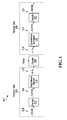
- the digital communications system 102 comprises a transmit side 104 and a receive side 106, separated by a channel 108.
- the transmit side 104 may comprise a transmitter
- the receive side 106 may comprise a receiver. It is desired to transmit a stream of binary digits 109 ("bits") from the transmit side 104 to the receive side 106.
- bits binary digits 109
- the channel 108 cannot support the literal propagation of a stream of bits directly (i.e. the channel medium cannot literally carry digital 1's and 0's). Instead, the bits 109 need to be mapped or modulated onto corresponding waveforms that can propagate through the channel 108.
- the channel 108 will typically be noisy and will therefore corrupt the transmitted signals, such that there is uncertainty at the receive side 106 as to what was actually transmitted.
- the receive side 106 therefore needs to make a "guess" or decision as to what was transmitted. Making an incorrect guess/decision will result in bit errors at the receive side 106.
- the transmit side 104 includes an encoder 112 and a constellation mapper 114.
- the encoder 112 performs error control coding. Specifically, the encoder 112 encodes the bits 109 to be transmitted so that redundancy is strategically added. This redundancy is then exploited on the receive side 106 to try and identify and/or correct errors introduced by the noise in the channel 108.
- Error control coding and error control codes are well known in the art. Examples of error control codes include linear block codes, cyclic codes, convolutional codes, and turbo codes.
- the output of the encoder 112 is a stream of encoded bits 116, which consist of the stream of bits 109 encoded using an error control code.
- the constellation mapper 114 sequentially maps groups of encoded bits 116 to corresponding symbols, which are ultimately mapped to waveforms that are suitable for transmission over the channel 108.
- the output of the constellation mapper 114 is therefore a stream of symbols 118.
- Each symbol corresponds to a specific group of bits, and each symbol can be represented as vectors or values in a signal constellation.
- the mapping of bits to symbols is what is typically referred to as modulation mapping.
- FIG. 2 illustrates a signal constellation for Pulse Amplitude Modulation (PAM) in which groups of 3 bits are each mapped to one of 8 corresponding symbols ( s 1 to s 8 ), each symbol corresponding to a particular permutation or pattern of bits.
- PAM Pulse Amplitude Modulation
- This modulation scheme is referred to as 8-PAM modulation.
- the amplitude of the signal is representative of the specific pattern of 3 bits that are being transmitted.
- There are 8 possible symbols s 1 to s 8 each one representing a unique pattern of 3-bit values.
- the constellation mapper 114 receives as its input "111", then it will transmit symbol s 1 , which has a value of -7 d in the constellation.
- the value "-7 d " relates to the energy of the transmitted bits. For example, it may correspond to (or be a function of) the amplitude of an actual transmitted signal. As an example, the value “ d " may correspond to (or be a function of) the energy of a baseband signal, which is further amplified depending upon what symbol is being transmitted.
- the value d also relates to the distance between a pair of adjacent constellation points. In the constellation of FIG.2 , there is a distance of 2 d between adjacent constellation points.
- the constellation mapper 114 receives as its input "001 ", then it will transmit symbol s 5 , which has a value of d in the constellation.
- the constellation mapper 114 can receive a continual or a continuous stream of encoded bits 116 and map and transmit over the channel 108 a corresponding stream of symbols 118, each symbol corresponding to a group of 3 bits.
- Gray coding is when two adjacent values only differ by one bit. As can be seen in the constellation in FIG. 2 , each pair of adjacent symbols represents a pair of adjacent bit patterns that only differ by one bit.
- AWGN additive white Gaussian noise
- Gray coding is not the only way to map bit patterns to symbols in the constellation. For example, the 8-PAM signal constellation shown in FIG. 3 maps the bit patterns to symbols using a different arrangement.
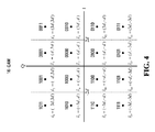
- FIG. 4 illustrates a signal constellation for Quadrature Amplitude Modulation (QAM) in which groups of 4 bits are each mapped to one of 16 corresponding symbols. This is referred to as 16-QAM.
- QAM Quadrature Amplitude Modulation
- this modulation scheme typically both the amplitude and the phase of each signal being transmitted is representative of the specific pattern of 4 bits that are being transmitted.
- Gray coding is used for mapping the bit patterns to the symbols. As will be appreciated, this is not the only Gray coding mapping available for this constellation, but is only one example.
- each symbol is represented by a value in the constellation.
- the symbol s 1 in the 16-QAM constellation shown in FIG. 4 is represented by the two dimensional value (-3d, 3d).
- the 8-PAM constellations shown in FIGs. 2 and 3 these are only one dimensional constellations, and so each symbol is simply just a single value.
- PAM and QAM constellations illustrated in FIGs. 2 to 4 are just examples. Many different constellations are known and can instead be used.
- the receive side 106 of the data communications system 102 includes a constellation demapper 120 and a decoder 122.
- the constellation demapper 120 demaps the received symbols 119, which have been corrupted by noise, to either bits (a "hard decision") or reliability values representing the likelihood that each transmitted bit is either a one or a zero.
- the output of the constellation demapper 120 is then fed to the decoder 122, which uses the output of the constellation demapper 120 and the known error control code applied by the encoder 112 to decode the stream of bits that were sent by the transmit side 104.
- the value y may then be demapped by the constellation demapper 120 back to a corresponding bit pattern ("the hard decision"), i.e., ideally back to "001" if the noise in the channel 108 did not corrupt the signal too much during transmission.
- the stream 124 of demapped values output from the constellation demapper 120 is then fed to the decoder 122, which decodes the stream 124 back to a stream of bits 126 (via the predetermined error control coding method), which represents the decision of the receive side 106. That is, the stream of bits 126 represents the decision as to the corresponding stream of bits 109 that were transmitted from the transmit side 104.
- the transmit side 104 and the receive side 106 will typically include many more components that are known in the art and that may be related to the transmission of the data, depending upon the specific implementation. Examples of such components include (but are not limited to): source coders/decoders, encryption/decryption, interleaving/deinterleaving, digital signal processing, filtering, OFDM modulation/demodulation, spreading/despreading, scrambling/descrambling, and mapping to/from subbands.
- source coders/decoders encryption/decryption
- interleaving/deinterleaving digital signal processing
- filtering OFDM modulation/demodulation
- spreading/despreading spreading/despreading
- scrambling/descrambling scrambling/descrambling
- the channel 108 can include both the actual transmission medium (e.g. air or cable) through which an analog signal propagates, as well as the analog-to-digital (A/D) conversion and any related amplification, filtering or digital signal processing.
- the noise can include both noise in the actual transmission medium and noise introduced in the A/D conversion and any related filtering or digital signal processing at the receive side and/or the transmit side.
- the decoder 122 may accept reliability values as an input instead of bit values (in which case the output of the constellation demapper 120 would not be bits 124, as illustrated, but would be reliability values corresponding to bits 124).
- Such a decoder is referred to as a "soft-input" decoder.
- Soft-input decoders for decoding turbo codes and Low-Density Parity-Check (LDPC) codes.
- LDPC Low-Density Parity-Check
- a soft-input Viterbi decoder is also known. Instead of accepting digital bits as an input to the decoder, a soft-input decoder accepts reliability values, one reliability value corresponding to each bit transmitted via the transmitted symbol.
- a reliability value can provide more information since it not only indicates which bit was more likely transmitted, but additionally the amplitude of the reliability value can indicate how likely it was that the particular bit was transmitted.
- the constellation demapper 120 Instead of the constellation demapper 120 outputting the 3-bit hard decision value representing the guess/decision of what was sent (e.g. the value "001" if there was not much corruption of the signal during transmission), the constellation demapper 120 instead outputs 3 reliability values, one for each bit.
- each reliability value may indicate through its sign whether the bit sent was likely a "0" or a "1”, and each reliability value may indicate through its absolute value how likely it was that that particular bit was sent. For example: (i) a large negative value may indicate that it was very likely that a "1" was sent; (ii) a small negative value may indicate that it was more likely than not that a "1” was sent, but there is significant uncertainty; (iii) a small positive value may indicate that it was more likely than not that a "0” was sent, but there is significant uncertainty; and (iv) a large positive value may indicate that it was very likely that a "0” was sent.
- These reliability values are then used by the soft-input decoder to perform error control decoding.
- LLR Log Likelihood Ratio
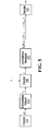
- FIG. 5 is an example embodiment of the digital communications system of FIG. 1 , with the assumption that the decoder 122 is a soft-input decoder that accepts as its input LLR values.
- the LLR values are output from the constellation demapper 120.
- the constellation demapper 120 outputs m LLR values, i.e., one LLR value for each bit represented by the received symbol value y.
- the transmitted symbol x b ⁇ may be corrupted by multiplicative noise (e.g. fading in a channel), but it is assumed that this is compensated for via known signal processing (e.g. equalizing).
- the additive noise n may represent additive noise in the channel medium and/or additive noise added through the filtering and signal processing (e.g. added through imperfect A/D conversion, equalization, etc.).
- the additive noise n may be or include the estimation error of the estimated symbol after channel equalization.
- y P b i 1
- y , i 0 , ... , m - 1
- the LLR L(b i ) for an i th bit of the m bits transmitted via the symbol x b is computed by:
- b ⁇ ⁇ b ⁇ , b i 1 P y
- b is a group of m bits (the "bit vector")
- x b ⁇ is the symbol associated with the bit vector
- the symbol ⁇ is the standard deviation of the Gaussian distribution of the noise n.
- Computing equation (2) is referred to as the Max-Log-MAP LLR calculation.
- Computing equation (2) may require fewer computational resources than computing equation (1). However, assuming that equation (2) is computed using an exhaustive search (brute force method), it can still involve a lot of computational resources, especially when the number of bits per symbol (i.e. m) is large. In particular, the complexity involves O ( m 2 m ) subtractions for PAM and O(m2 m / 2 ) subtractions for QAM.
- the received symbol value y is used by the constellation demapper 120 to obtain an LLR value for each of the m bits corresponding to y.
- the received symbol value y may be "soft sliced" into m values, one for each of the m bits represented by the value y. These soft sliced values can then be used to obtain the LLR for each of the m bits.
- Soft slicing a received value y refers to a method of deriving m values from the received value y in a way that facilitates computation of a reliability value (such as the LLR) for each of the m bits using the soft sliced values. Typically, the soft slicing is also performed in a way that is intuitively meaningful.
- the PAM constellation can be "folded-and-overlapped". That is, a "fold-and-overlap" approach can be taken. Specifically, in order to obtain the i th coordinate axis for slicing the soft value y i , the right half of the ( i -1) th coordinate axis is folded and overlapped with the left half. The origin, i.e. the decision boundary, is shifted to the left by 2 m - i d . The received symbol value y is also folded to the left if it is on the right half of the axis.
- the first soft sliced value corresponds to the most significant bit
- the decision threshold of the most significant bit is the origin. That is, due to the Gray coding, all the most significant bits on the left side of the axis are "1", and all the most significant bits on the right side of the axis are "0", and so the decision as to what most significant bit was sent can be made by the sign of the received value y (i.e., if y is negative then "1" was most likely sent and if y is positive then "0" was most likely sent).
- the absolute value of y also indicates how likely it is that that particular bit was sent, since the farther the value y is from the origin, the more likely the particular bit was sent. Thus, for the most significant bit, the value of y itself is a good soft-sliced value y 0 for the most significant bit.
- the new origin of the folded axis is now the decision threshold for the middle bit. That is, on the left side of folded axis all the middle bits are "1", and on the right side of the folded axis all the middle bits are "0". Therefore, the received value y on the folded axis is representative of a good soft sliced value y 1 for the middle bit.
- the received value y on the folded axis is 4 d -
- the soft-sliced value y 1 is 4 d -
- the new origin of the double-folded axis is now the decision threshold for the least significant bit. That is, on the left side of the double-folded axis all the least significant bits are "1", and on the right side of the double-folded axis all the least significant bits are "0".
- the received value y on the double-folded axis is representative of a good soft sliced value y 2 for the least significant bit.
- the received value y on the double-folded axis is 2 d -
- the soft-sliced value y 2 is 2 d -
- the purpose of soft slicing the received value y is to facilitate the computation of reliability values, such as the LLR.
- LLR for each of the m bits received via the symbol value y is computed as shown in equation (2):
- the hard decision b ⁇ corresponding to the received value y is the pattern of bits representing the constellation demapper's decision/guess as to what pattern of bits were most likely sent via the received symbol.
- the hard decision is the most likely pattern of m bits transmitted given the received value y.
- the hard decision of the received symbol value y is the bit pattern corresponding to the transmitted symbol x b ⁇ that is closest to the received symbol value y in the constellation.
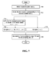
- the following method can be performed in order to compute the LLR of equation (2) for each of the m bits corresponding to a received symbol value y. This method is described with reference to FIG. 7 and is performed by the constellation demapper 120.
- step 710 the constellation demapper 120 obtains the received symbol value y.
- the constellation demapper 120 obtains the hard decision corresponding to the received value y.
- the hard decision corresponding to the received value y is the most likely pattern of m bits transmitted given the received value y.
- the hard decision of the received symbol value y is the bit pattern corresponding to the transmitted symbol that is closest to the received symbol value y in the constellation.
- the hard decision consists of a pattern of m bits: b 0 ⁇ b 1 ... b m - 1 .
- the constellation demapper 120 soft slices the received symbol value y to obtain the m soft-sliced values y 0 ,..., y m-1 .
- the constellation demapper 120 computes
- y - x b ⁇ min b ⁇
- b i b ⁇ i ⁇ y - x b ⁇ .
- b ⁇ is simply the distance to the symbol x b ⁇ in the constellation representing the hard decision. That is,
- the closest constellation point on this folded axis is either d or - d (depending on which side of the decision threshold y m-1 is on), and therefore the distance between y m-1 and its closest constellation point is
- step 718 the constellation demapper 120 then computes d +
- d + y i min b ⁇ , b i ⁇ b ⁇ i ⁇ y - x b ⁇ .
- steps 716 and 718 may be computed in any order, or even in parallel (as illustrated). Also, step 716 may be computed in parallel with one or both of steps 714 and 718.
- equation (2) is still computed exactly. That is, no approximation has been introduced to reduce complexity, just simplifications using the combination of the observations above.
- and y 2 2d-
- the distance to the closest to the symbol x b ⁇ (which corresponds to the hard decision) is computed. As discussed above in relation to step 716, this can be computed by
- step 718 the value d +
- d + y 0 min b ⁇ , b 0 ⁇ b ⁇ 0 ⁇ y - x b ⁇
- the other LLR values L ( b 1 ) and L ( b 2 ) may also be computed using the method above.
- the method of FIG. 7 requires the hard decision b 0 b 1 ...b m-1 .
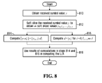
- Another embodiment is described with reference to FIG. 8 in which it is not necessary to explicitly compute the hard decision. This may save additional computations.
- step 810 the constellation demapper 120 obtains the received symbol value y.
- the constellation demapper 120 soft slices the received symbol value y to obtain the m soft-sliced values y 0 ,..., y m-1 .
- step 814 the constellation demapper 120 computes
- step 816 the constellation demapper 120 then computes d+
- d + y i min b ⁇ , b i ⁇ b ⁇ i ⁇ y - x b ⁇ .
- steps 814 and 816 may be computed in any order, or even in parallel (as illustrated).
- FIG. 9 A variation of the method of FIG. 8 is shown with reference to FIG. 9 .
- the sign of each soft sliced value y i is explicitly used to determine which computation to perform in the steps corresponding to steps 814 and 816 of the method of FIG. 8 .
- step 910 the constellation demapper 120 obtains the received symbol value y.
- the constellation demapper 120 soft slices the received symbol value y to obtain the m soft-sliced values y 0 ,..., y m- 1 .
- + d , y i ⁇ 0 y m - 1 - d , y i ⁇ 0 , i 0 , ... , m - 1
- FIGs. 7 to 9 assume Gray coding. However, the methods described herein need not be limited to Gray coding. Instead, the methods described herein can be adapted for other modulation schemes and/or other bit-to-symbol mappings. However, the exact way in which the received value y is soft sliced will typically need to be modified to complement the bit-to-symbol mapping of the constellation.
- This soft slicing technique is also intuitively meaningful as follows.
- the PAM constellation can be shifted and overlapped. This is referred to as a "shift-and-overlap" approach.
- the left half of the ( i -1) th coordinate axis is shifted to the right by 2 m-i d
- the right half of the ( i - 1) th coordinate axis is shifted to the left by 2 m-i d.
- the right and left halves of the ( i -1) th coordinate axes therefore overlap.
- the received value y is also shifted by the same amount as the side of the axis it is on.
- the origin, i.e. the decision boundary is not moved.
- the new value of y indicates the next soft sliced value.
- m 3 soft sliced values are derived from the received symbol value y (i.e. y 0 , y 1 , and y 2 , respectively corresponding to the most significant bit, the middle bit, and the least significant bit of the 3 bits transmitted via the transmitted symbol).
- the received symbol value y has a value between 0 and - d, as shown in the first step of FIG. 11 .
- the first soft sliced value y 0 is simply taken as the value y. Intuitively, this is because the first soft sliced value corresponds to the most significant bit, and the decision threshold of the most significant bit in this constellation is the origin.
- the received symbol is also shifted by the same amount as the side of the axis it is on.
- the origin, i.e, the decision boundary remains the same. With this shift, the origin of the overlapped axis is now the decision threshold for the middle bit.
- the received symbol on the overlapped axis is representative of a good soft sliced value y 1 for the middle bit.
- the position of the received symbol on the overlapped axis will depend on whether it was on the right side of the original axis (i.e. y 0 ⁇ 0) or whether it was on the left side of the original axis (i.e. y 0 ⁇ 0). If it were on the right side of the original axis (i.e.
- the position of the received symbol on the overlapped axis would be y 0 - 4 d.
- the received symbol is on the left side of the original axis (i.e. y 0 ⁇ 0), and therefore its position on the overlapped axis is y 0 + 4 d.
- the soft-sliced value y 1 is y 0 + 4 d.
- the received symbol is again shifted by the same amount as the side of the axis it is on.
- the origin, i.e, the decision boundary remains the same. With this shift, the origin of the double overlapped axis is now the decision threshold for the least significant bit.
- the received symbol on the double overlapped axis is representative of a good soft sliced value y 2 for the least significant bit.
- the position of the received symbol on the double overlapped axis will depend on whether it was on the right side of the single overlapped axis (i.e. y 1 ⁇ 0) or whether it was on the left side of the single overlapped axis (i.e. y 1 ⁇ 0). In this example, it is on the right side of the single overlapped axis (i.e. y 1 ⁇ 0), and therefore its position on the double overlapped axis is y 1 - 2 d.
- bit to symbol mappings For other bit to symbol mappings, the methods above can still be applied, but using a soft slicing technique that complements the specific bit to symbol mapping of the constellation. Two different bit to symbol mappings and associated soft slicing methods are discussed above by way of example only. Others are possible.
- a square or a rectangular QAM can typically be decomposed into two independent PAM signals, i.e., in-phase and quadraphase signals.
- a group of consecutive bits at the input of the constellation mapper can be separated into two sub-groups, in the in-phase bits and the quadraphase bits. Both sub-groups are mapped to a PAM signal, and then the two PAM signals are combined to form a square or rectangular QAM signal.
- FIG. 12 shows a Gray coded 64-QAM signal that can be decomposed into two independent Gray coded 8-PAM signals.
- each group of six consecutive bits is separated alternatively into two sub-groups, the in-phase bits (illustrated on the top of the figure and bolded), and the quadraphase bits (illustrated on the left of the figure). Both sub-groups are mapped to a Gray coded 8-PAM signal, and then the two signals are combined to form a Gray coded 64-QAM signal.
- the in-phase and quadraphase bits are interleaved.
- the rectangular or square mapper/demapper can be implemented by two independent PAM constellation mappers/demappers, as shown in FIG. 13 , and when performing the demapping, the PAM demapping methods described herein may be used.
- bit separation and collection in FIG. 12 is not limited to the particular QAM constellation illustrated, which is Gray coded and in which the in-phase and quadraphase bits are interleaved.
- Other coding and bit separation schemes are also possible, such as Gray coded QAM in which the in-phase and quadraphase bits are concatenated, or natural coded QAM where the in-phase and quadraphase bites are interleaved.
- the QAM constellations in references [1] to [4] can be implemented by two independent PAM constellation mappers/demappers. The bibliographic information for references [1] to [4] is at the end of this description.
- equation (2) is still computed exactly.
- the table below shows an example of the complexity reduction achieved in certain applications in comparison to computing the LLR in equation (2) using an exhaustive search.
- the method using an exhaustive search is assumed to calculate the distances between the received symbol and PAM constellation points on the fly. Hence it results in m ⁇ 2 m 2 + 1 - 1 additions/subtractions/comparisons.
- Other exhaustive search implementations are possible, e.g.
- LLR Log Likelihood Ratio
- the constellation comprises a set of constellation points having a minimum distance of 2 d between a pair of the constellation points. Examples of such constellations are shown in FIGs. 2 to 4 , 10 , and 12 , although these are only specific examples.
- the received symbol value y represents m bits that were transmitted using a modulation scheme of the constellation.
- m initial values y 0 ,y 1 ..., y m- 1 are obtained from the received symbol value y , one for each of the m bits. These initial values may be soft sliced values and/or may be obtained by soft slicing the received symbol value y.
- soft slicing is a method of deriving m values from the received value y in a way that facilitates computation of a reliability value for each of the m bits using the soft sliced values.
- the soft slicing is also performed in a way that is intuitively meaningful, but this need not be the case. Two specific soft-slicing techniques are discussed above. The specific soft slicing method used is implementation specific and depends upon the bit-to-symbol mapping of the constellation.
- the i th minimum distance value and the other minimum distance value may be combined by subtracting one from the other, by adding the two together, by multiplying or dividing the two, or by incorporating the two values into any computation that results in a single value.
- computations may be reduced (e.g. by only computing d +
- m reliability values are computed. In other embodiments, fewer than m reliability values may be computed (e.g. only one reliability value may be computed for one of the bits). In this case, the method of FIG. 14 would be modified to only compute a subset of reliability values.
- the other bits for which reliability values were not computed may, for example, be represented by their hard decision.
- the method of FIG. 14 is generalized. For example, a method for computing initial values is not specified. The initial values do not even have to be computed by soft slicing. Also, a specific constellation is not specified, and a specific reliability computation is not specified. FIG. 14 demonstrates that the methods described herein can be generalized to constellations, reliability value computations, methods for obtaining initial values, and other demapping scenarios. Step 1404 uses results discussed in both observations (2) and (3) to compute the reliability values.
- the other minimum distance value may be computed in the method of FIG. 14 by obtaining the hard decision, and then directly computing the distance between the received symbol value y and the symbol x b ⁇ in the constellation corresponding to the hard decision (i.e. by computing
- the hard decision is the most likely pattern of bits transmitted given the received symbol value y.
- the other minimum distance value may instead be computed in the method of FIG. 14 by computing
- the other minimum distance value may represent a minimum of a set comprising the distances between the received symbol value y and all points in the constellation having an associated bit pattern in which a given bit equals the corresponding bit in a hard decision associated with the received symbol value y.
- may represent a minimum of a set comprising the distances between the received symbol value y and all points in the constellation having an associated bit pattern in which the i th bit does not equal the i th bit of the hard decision.
- LLR Log Likelihood Ratio
- ), and min b ⁇ , b i 1 ⁇ y - x b ⁇ may computed as the i th mimimum distance value d+
- and min b ⁇ , b i 1 ⁇ y - x b ⁇ may be computed as the other mimimum distance value.
- the i th minimum distance value and the other minimum distance value are combined by subtracting one from the other.
- the constellation may use Gray coding, natural coding, or another type of coding.
- the constellation may be square QAM or rectangular QAM
- the demapping may be performed by decomposing the QAM constellation into two independent PAM constellations representing an in-phase and a quadrature-phase signal respectively, and independently demapping each of the two independent PAM constellations.
- the value d may be a function of the received energy per bit, or vice versa.
- the methods described herein may further comprise performing the demapping for a plurality of received symbols, and decoding the plurality of received symbols using the reliability values as inputs to a soft-input decoder.
- the demapping is performed at the receiving end of a device (e.g. a mobile device).
- the demapping may be performed at a receiver or in a processing unit connected to or part of the receiver.
- the demapping is performed by a constellation demapper.
- the constellation demapper may be implemented in a receiver in a communication system, or in a processing unit or a digital processing module connected to or part of the receiver (or receiving end).
- the computational steps disclosed herein may be implemented in (and therefore performed by) a digital signal processor or a field programmable gate array (FPGA) or an integrated circuit.
- FPGA field programmable gate array
- the one or more reliability values may be forwarded to a soft-input decoder. However, it is not necessary that the reliability values be forwarded to a decoder, depending on the implementation and envisioned use of the reliability values.
- any or all of the methods described herein may be implemented in a mobile device or any other device that communicates over a wireless channel.
- the method may further comprise receiving a wireless signal from a wireless channel, obtaining the received symbol value y from the wireless signal, and performing decoding using some or all reliability values.
- the reliability value is computed as follows.
- a first minimum distance value is obtained, the first minimum distance value being a function of an absolute magnitude of an initial value associated with the bit.
- the first minimum distance value is combined with a second minimum distance value, the second minimum distance value being a function of a distance between the received symbol value y and a symbol x b ⁇ in the constellation corresponding to a most likely pattern of bits transmitted given the received symbol value y .
- first minimum distance value and the second minimum distance value are incorporated into a single value or used to compute a single value.
- first minimum distance value and the second minimum distance value may be combined by subtracting one from the other, by adding the two together, by multiplying or dividing the two, or by incorporating the two values into any computation that results in a single value.
- FIG. 16 illustrates an embodiment of an apparatus 1202 in a receiving side 1204 of a digital communications system.
- the apparatus includes a constellation demapper 1206 for performing the demapping (and hence reliability value computation(s)) in accordance with any of the embodiments described above.
- the demapper 1206 may implement the method of FIG. 14 or FIG. 15 .
- the apparatus 1202 may further include a decoder (such as a soft input decoder) for decoding using the reliability values computed by the demapper 1206.
- a decoder such as a soft input decoder
- the apparatus 1202 may further include a receiver for receiving a signal from a channel (such as a wireless signal from a wireless channel), and processing circuitry for obtaining the received symbol value from the received signal.
- a receiver for receiving a signal from a channel (such as a wireless signal from a wireless channel)
- processing circuitry for obtaining the received symbol value from the received signal.
- the apparatus 1202 is part of a mobile device, although this need not be the case (the methods described herein are also applicable to wireline communications systems).
- a computer readable medium having stored thereon computer executable instructions that, when executed, cause an apparatus (such as a computing device, a mobile device, etc.) to perform any of the methods described herein.
- an apparatus such as a computing device, a mobile device, etc.
- FIG. 17 a block diagram is shown of a specific example of a mobile device 1100 that may implement any of the methods described herein.
- the mobile device 1100 is shown with specific components for implementing different features including (for example), the methods described herein. It is to be understood that the mobile device 1100 is shown with very specific details for exemplary purposes only.
- the mobile device 1100 has a housing that may be elongated vertically, or may take on other sizes and shapes (including clamshell housing structures).
- the keyboard 1114 may include a mode selection key, or other hardware or software for switching between text entry and telephony entry.
- the mobile device 1100 may have a housing that does not take on other sizes and shapes.
- a microprocessor 1128 is shown schematically as coupled between a keyboard 1114 and a display 1126.
- the microprocessor 1128 controls operation of the display 1126, as well as overall operation of the mobile device 1100, in response to actuation of keys on the keyboard 1114 by a user.
- a communications subsystem 1170 In addition to the microprocessor 1128, other parts of the mobile device 1100 are shown schematically. These include: a communications subsystem 1170; a short-range communications subsystem 1102; the keyboard 1114 and the display 1126, along with other input/output devices including a set of LEDs 1104, a set of auxiliary I/O devices 1106, a serial port 1108, a speaker 1111 and a microphone 1112; as well as memory devices including a flash memory 1116 and a Random Access Memory (RAM) 1118; and various other device subsystems 1120.
- the keyboard 1114, speaker 111, microphone 1112, display 1126, and LEDs 1104 are part of the user-interface.
- the mobile device 1100 may have a battery 1121 to power the active elements of the mobile device 1100.
- the mobile device 1100 is in some embodiments a two-way radio frequency (RF) communication device having voice and data communication capabilities.
- the mobile device 1100 in some embodiments has the capability to communicate with other computer systems via the Internet.
- the two-way RF communication is for communicating with a network.
- Operating system software executed by the microprocessor 1128 is in some embodiments stored in a persistent store, such as the flash memory 1116, but may be stored in other types of memory devices, such as a read only memory (ROM) or similar storage element.
- system software, specific device applications, or parts thereof may be temporarily loaded into a volatile store, such as the RAM 1118.
- Communication signals received by the mobile device 1100 may also be stored to the RAM 1118.
- the microprocessor 1128 in addition to its operating system functions, enables execution of software applications on the mobile device 1100.
- a predetermined set of software applications that control basic device operations such as a voice communications module 1130A and a data communications module 1130B, may be installed on the mobile device 1100 during manufacture.
- a personal information manager (PIM) application module 1130C may also be installed on the mobile device 1100 during manufacture.
- the PIM application is in some embodiments capable of organizing and managing data items, such as e-mail, calendar events, voice mails, appointments, and task items.
- the PIM application is also in some embodiments capable of sending and receiving data items via a wireless network 1110.
- the data items managed by the PIM application are seamlessly integrated, synchronized and updated via the wireless network 1110 with the device user's corresponding data items stored or associated with a host computer system.
- Additional software modules illustrated as another software module 1130N, may be installed during manufacture.
- the communication subsystem 1170 includes a receiver 1150, a transmitter 1152, a GPS receiver 1162, and one or more antennas, illustrated as a receive antenna 1154, a transmit antenna 1156, and a GPS antenna 1164.
- the communication subsystem 1170 also includes a processing module, such as a digital signal processor (DSP) 1158, and local oscillators (LOs) 1160.
- DSP digital signal processor
- LOs local oscillators
- the communication subsystem 1170 is dependent upon the communication network in which the mobile device 1100 is intended to operate.
- the communication subsystem 1170 of the mobile device 1100 may be designed to operate with the MobitexTM, DataTACTM or General Packet Radio Service (GPRS) mobile data communication networks and also designed to operate with any of a variety of voice communication networks, such as Advanced Mobile Phone Service (AMPS), Time Division Multiple Access (TDMA), Code Division Multiple Access (CDMA), Personal Communications Service (PCS), Global System for Mobile Communications (GSM), etc. Examples of CDMA include 1X and 1x EV-DO.
- the communication subsystem 1170 may also be designed to operate with an 802.11 Wi-Fi network, and/or an 802.16 WiMAX network. Other types of data and voice networks, both separate and integrated, may also be utilized with the mobile device 1100.
- Network access may vary depending upon the type of communication system. For example, in the MobitexTM and DataTACTM networks, mobile devices are registered on the network using a unique Personal Identification Number (PIN) associated with each device. In GPRS networks, however, network access is typically associated with a subscriber or user of a device. A GPRS device therefore typically has a UICC, in order to operate on a GPRS network.
- PIN Personal Identification Number
- the mobile device 1100 may send and receive communication signals over the communication network 1110.
- Signals received from the communication network 1110 by the receive antenna 1154 are routed to the receiver 1150, which provides for signal amplification, frequency down conversion, filtering, channel selection, etc., and may also provide analog to digital conversion. Analog-to-digital conversion of the received signal allows the DSP 1158 to perform more complex communication functions, such as constellation demapping (e.g. via the methods described above) and decoding.
- signals to be transmitted to the network 1110 are processed (e.g., modulated and encoded) by the DSP 1158 and are then provided to the transmitter 1152 for digital to analog conversion, frequency up conversion, filtering, amplification and transmission to the communication network 110 (or networks) via the transmit antenna 1156.
- signals to be transmitted to the network 1110 are processed (e.g., modulated and encoded) by the DSP 1158 and are then provided to the transmitter 1152 for digital to analog conversion, frequency up conversion, filtering, amplification and transmission to the communication network 110 (or networks) via the transmit antenna 1156.
- the DSP 1158 provides for control of the receiver 1150, the transmitter 1152, and the GPS receiver 1162. For example, gains applied to communication signals in the receiver 1150 and the transmitter 1152 may be adaptively controlled through automatic gain control algorithms implemented in the DSP 1158.
- a received signal such as a text message or downloaded web page
- the communication subsystem 1170 is input to the microprocessor 1128.
- the received signal is then further processed by the microprocessor 1128 for an output to the display 1126, or alternatively to some other auxiliary I/O devices 1106.
- a device user may also compose data items, such as e-mail messages, using the keyboard 1114 and/or some other auxiliary I/O device 1106, such as a touchpad, a rocker switch, a thumb-wheel, or some other type of input device.
- the composed data items may then be transmitted over the communication network 1110 via the communication subsystem 1170.
- a voice communication mode In a voice communication mode, overall operation of the device is substantially similar to the data communication mode, except that received signals are output to a speaker 1111, and signals for transmission are generated by a microphone 1112.
- Alternative voice or audio I/O subsystems such as a voice message recording subsystem, may also be implemented on the mobile device 1100.
- the display 1126 may also be utilized in voice communication mode, for example, to display the identity of a calling party, the duration of a voice call, or other voice call related information.
- GPS Location determination using GPS technology involves receiving GPS signals from GPS satellites 1166 on the antenna 1164.
- the GPS signals are received using the GPS receiver 1162 and processed by the DSP 1158.
- GPS signals from at least four satellites are processed. Further details of GPS are known in the art and are omitted for simplicity.
- the short-range communications subsystem 1102 enables communication between the mobile device 1100 and other proximate systems or devices, which need not necessarily be similar devices.
- the short range communications subsystem may include an infrared device and associated circuits and components, or a BluetoothTM communication module to provide for communication with similarly-enabled systems and devices.
Landscapes
- Engineering & Computer Science (AREA)
- Power Engineering (AREA)
- Computer Networks & Wireless Communication (AREA)
- Signal Processing (AREA)
- Digital Transmission Methods That Use Modulated Carrier Waves (AREA)
- Error Detection And Correction (AREA)
Priority Applications (1)
| Application Number | Priority Date | Filing Date | Title |
|---|---|---|---|
| EP13159254.5A EP2779552A1 (fr) | 2013-03-14 | 2013-03-14 | Calcul de valeurs de fiabilité |
Applications Claiming Priority (1)
| Application Number | Priority Date | Filing Date | Title |
|---|---|---|---|
| EP13159254.5A EP2779552A1 (fr) | 2013-03-14 | 2013-03-14 | Calcul de valeurs de fiabilité |
Publications (1)
| Publication Number | Publication Date |
|---|---|
| EP2779552A1 true EP2779552A1 (fr) | 2014-09-17 |
Family
ID=47900811
Family Applications (1)
| Application Number | Title | Priority Date | Filing Date |
|---|---|---|---|
| EP13159254.5A Withdrawn EP2779552A1 (fr) | 2013-03-14 | 2013-03-14 | Calcul de valeurs de fiabilité |
Country Status (1)
| Country | Link |
|---|---|
| EP (1) | EP2779552A1 (fr) |
Citations (3)
| Publication number | Priority date | Publication date | Assignee | Title |
|---|---|---|---|---|
| US6078626A (en) * | 1997-09-24 | 2000-06-20 | Ericsson Inc. | Methods and systems for communicating information using separable modulation constellations |
| EP1246419A1 (fr) * | 2001-03-12 | 2002-10-02 | Motorola, Inc. | Dispositif et procédé de calcul de la vraisemblance logarithmique pour la modulation d'amplitude en quadrature |
| US20110019726A1 (en) * | 2008-03-18 | 2011-01-27 | Cambridge Silicon Radio Limited | Method and apparatus for performing log-likelihood calculations |
-
2013
- 2013-03-14 EP EP13159254.5A patent/EP2779552A1/fr not_active Withdrawn
Patent Citations (3)
| Publication number | Priority date | Publication date | Assignee | Title |
|---|---|---|---|---|
| US6078626A (en) * | 1997-09-24 | 2000-06-20 | Ericsson Inc. | Methods and systems for communicating information using separable modulation constellations |
| EP1246419A1 (fr) * | 2001-03-12 | 2002-10-02 | Motorola, Inc. | Dispositif et procédé de calcul de la vraisemblance logarithmique pour la modulation d'amplitude en quadrature |
| US20110019726A1 (en) * | 2008-03-18 | 2011-01-27 | Cambridge Silicon Radio Limited | Method and apparatus for performing log-likelihood calculations |
Similar Documents
| Publication | Publication Date | Title |
|---|---|---|
| US20140270000A1 (en) | Computation of Reliability Values | |
| Valenti et al. | Iterative demodulation and decoding of turbo-coded M-ary noncoherent orthogonal modulation | |
| Barbieri et al. | Time-frequency packing for linear modulations: spectral efficiency and practical detection schemes | |
| Wu et al. | Iterative multiuser receiver in sparse code multiple access systems | |
| US11133973B2 (en) | Methods and apparatuses for quadrature amplitude modulation optimized for phase noise | |
| US20020131515A1 (en) | Soft-decision metric generation for higher order modulation | |
| Rashich et al. | FFT-based trellis receiver for SEFDM signals | |
| EP3406063B1 (fr) | Procédé et appareil de modulation de signal en quadrature | |
| ES2362759B1 (es) | Procedimiento y dispositivo de comunicaciones digitales para la recepción de datos usando simbolos qam. | |
| Xu et al. | Reduced-complexity approx-log-MAP and max-log-MAP soft PSK/QAM detection algorithms | |
| Zhang et al. | Polar-coded OFDM with index modulation | |
| Arbi et al. | Uniformly projected RCQD QAM: A low-complexity signal space diversity solution over fading channels with or without erasures | |
| Chen et al. | Noncoherent amplitude/phase modulated transmission schemes for Rayleigh block fading channels | |
| Yang et al. | Max-log demapper architecture design for DVB-T2 rotated QAM constellations | |
| Yazdani et al. | Efficient LLR calculation for non-binary modulations over fading channels | |
| Shen et al. | Joint detection and decoding for polar coded MIMO systems | |
| EP2362597B1 (fr) | Procédé pour la réalisation d'une coupure de taux de vraisemblances logarithmiques dans un détecteur quasi-ML à décision pondérée et détecteur correspondant | |
| Tavildar | Bit-permuted coded modulation for polar codes | |
| EP2680520B1 (fr) | Procédé et dispositif de réception efficace et à complexité réduite de signaux dans un système de communication de type MIMO | |
| Valenti et al. | Iterative multisymbol noncoherent reception of coded CPFSK | |
| Navazi et al. | A novel symbol mapping method for BICM-ID systems for higher order signal constellations | |
| EP2779552A1 (fr) | Calcul de valeurs de fiabilité | |
| Ishibashi et al. | Low-complexity bit-interleaved coded DAPSK for Rayleigh-fading channels | |
| Fan et al. | Low-complexity rotated QAM demapper for the iterative receiver targeting DVB-T2 standard | |
| Espluga et al. | LLR approximation for fading channels using a Bayesian approach |
Legal Events
| Date | Code | Title | Description |
|---|---|---|---|
| PUAI | Public reference made under article 153(3) epc to a published international application that has entered the european phase |
Free format text: ORIGINAL CODE: 0009012 |
|
| 17P | Request for examination filed |
Effective date: 20130314 |
|
| AK | Designated contracting states |
Kind code of ref document: A1 Designated state(s): AL AT BE BG CH CY CZ DE DK EE ES FI FR GB GR HR HU IE IS IT LI LT LU LV MC MK MT NL NO PL PT RO RS SE SI SK SM TR |
|
| AX | Request for extension of the european patent |
Extension state: BA ME |
|
| RIN1 | Information on inventor provided before grant (corrected) |
Inventor name: LIU, XIANG Inventor name: KOSAKOWSKI, MARTIN |
|
| STAA | Information on the status of an ep patent application or granted ep patent |
Free format text: STATUS: THE APPLICATION HAS BEEN WITHDRAWN |
|
| 18W | Application withdrawn |
Effective date: 20141215 |