EP2779632B1 - Elektronische vorrichtung und deren betriebsverfahren - Google Patents
Elektronische vorrichtung und deren betriebsverfahren Download PDFInfo
- Publication number
- EP2779632B1 EP2779632B1 EP14158855.8A EP14158855A EP2779632B1 EP 2779632 B1 EP2779632 B1 EP 2779632B1 EP 14158855 A EP14158855 A EP 14158855A EP 2779632 B1 EP2779632 B1 EP 2779632B1
- Authority
- EP
- European Patent Office
- Prior art keywords
- image
- frame region
- images
- stationary object
- image data
- Prior art date
- Legal status (The legal status is an assumption and is not a legal conclusion. Google has not performed a legal analysis and makes no representation as to the accuracy of the status listed.)
- Active
Links
Images


Classifications
-
- H—ELECTRICITY
- H04—ELECTRIC COMMUNICATION TECHNIQUE
- H04N—PICTORIAL COMMUNICATION, e.g. TELEVISION
- H04N5/00—Details of television systems
- H04N5/222—Studio circuitry; Studio devices; Studio equipment
- H04N5/262—Studio circuits, e.g. for mixing, switching-over, change of character of image, other special effects ; Cameras specially adapted for the electronic generation of special effects
-
- H—ELECTRICITY
- H04—ELECTRIC COMMUNICATION TECHNIQUE
- H04N—PICTORIAL COMMUNICATION, e.g. TELEVISION
- H04N5/00—Details of television systems
- H04N5/222—Studio circuitry; Studio devices; Studio equipment
- H04N5/262—Studio circuits, e.g. for mixing, switching-over, change of character of image, other special effects ; Cameras specially adapted for the electronic generation of special effects
- H04N5/265—Mixing
-
- G—PHYSICS
- G06—COMPUTING OR CALCULATING; COUNTING
- G06T—IMAGE DATA PROCESSING OR GENERATION, IN GENERAL
- G06T1/00—General purpose image data processing
-
- G—PHYSICS
- G06—COMPUTING OR CALCULATING; COUNTING
- G06T—IMAGE DATA PROCESSING OR GENERATION, IN GENERAL
- G06T7/00—Image analysis
- G06T7/20—Analysis of motion
-
- G—PHYSICS
- G06—COMPUTING OR CALCULATING; COUNTING
- G06V—IMAGE OR VIDEO RECOGNITION OR UNDERSTANDING
- G06V40/00—Recognition of biometric, human-related or animal-related patterns in image or video data
- G06V40/20—Movements or behaviour, e.g. gesture recognition
-
- H—ELECTRICITY
- H04—ELECTRIC COMMUNICATION TECHNIQUE
- H04B—TRANSMISSION
- H04B1/00—Details of transmission systems, not covered by a single one of groups H04B3/00 - H04B13/00; Details of transmission systems not characterised by the medium used for transmission
- H04B1/38—Transceivers, i.e. devices in which transmitter and receiver form a structural unit and in which at least one part is used for functions of transmitting and receiving
- H04B1/40—Circuits
Definitions
- the present disclosure relates generally to image analysis, and more particularly to image transformation.
- GUI graphical user interface
- US-2008/080779-A1 discloses an image coding apparatus including a particular region detecting unit configured to detect a particular region whose hue is within a predetermined range and whose amount of movement or amount of shift between different frames is a threshold or more from chronologically input pictures forming an image; and a coding unit configured to perform coding on a picture in a frame in which the particular region detected by the particular region detecting unit is replaced with a predetermined picture other than the particular region, while detecting a motion vector between the frames.
- WO-2011/152841-A1 discloses a system and a method that use a background model to determine and to segment target content from an image and replace them with different content to provide a composite image.
- the background model can be generated based on image data representing images of a predetermined area that does not include traversing content.
- the background model is compared to image data representing a set of captured images of the predetermined area. Based on the comparison, portions of an image that differs from the background model are determined as the traversing content.
- a target content model is used to determine the target content in the traversing content.
- the target content determined in the images is replaced with different content to provide a composite image.
- an electronic device according to claim 8.
- an image processing method and apparatus capable of receiving images captured by an image sensor, detecting non-stationary objects in the images, selecting a first image including a non-stationary object, selecting a frame region including the non-stationary object in the first image, replacing image data in the frame region of the first image with image data from the frame region of the second image, and displaying the first image with the replaced image on the display.
- an electronic device capable of replacing image data in a region with image data from another image, when an image from consecutively photographed or captured images is displayed on a screen, and the region selected by a user includes at least some image data representing non-stationary objects.
- an image processing method includes receiving images capturing a scene, each image taken at a different time, detecting a non-stationary object in the images, selecting a first image including the non-stationary object, selecting a frame region including the non-stationary object in the first image, selecting a second image having a low similarity with the first image, replacing image data in the frame region of the first image with image data from the frame region of the second image, and displaying the first image with the replaced image data on a display.
- an electronic device includes an obtaining module configured to receive a plurality of images of a scene, a detection module configured to detect a non-stationary object in the plurality of images and measure similarity between images in the plurality of images, a region module configured to select a frame region designating the non-stationary object, a manipulation module configured to replace image data of the frame region in a first image of the plurality of images with image data of the frame region from a second image of the plurality of images when the second image has low similarity to the first image, and a display configured to display the first image with the replaced image data.
- an electronic device includes at least one processor, at least one display, at least one memory, and at least one program stored in the memory and configured to be executable by the at least one processor to receive images capturing a scene, each image taken at a different time, detect a non-stationary object image data in the images, select a first image including the non-stationary object, select a frame region including the non-stationary object in the first image, select a second image having a low similarity with the first image, replace image data represented in the frame region of the first image with image data in the frame region of the second image, and display the first image with the replaced image data on the display.
- the present invention discloses a method and apparatus to conduct image processing on a plurality of images.
- a consecutive sequence of images is taken, capturing the same scene at different times.
- Non-stationary objects may be captured among the plurality of images, these non-stationary objects being for example, people, animals, cars, and other moving objects. It is the goal of the present invention to enable the removal of one or more of the non-stationary objects from one of the images in the plurality of images. This may be done by defining a frame region in one picture that contains a non-stationary object, and replacing it when the same frame region from another picture in the plurality of images that does not contain the non-stationary object.
- one or more non-stationary objects may be removed from the picture, creating a final single picture that is a composite of two or more images from the plurality of images, lacking the undesired non-stationary objects.
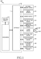
- FIG. 1 illustrates a block diagram of a user device according to an embodiment of the present invention.
- the user device 100 may be a mobile phone, a mobile pad, a media player, a tablet computer, a handheld computer, or a personal digital assistant (PDA) or some similar portable computing device. Additionally, the user device 100 may be any mobile terminal including a device having two or more functions combined from the above-described devices.
- PDA personal digital assistant
- the user device 100 may include a host device 110, an external memory device 121, an image sensor 122, a sensor device 123, a global position system (GPS) reception device 124, a wireless communication device 125, an audio device 126, an external port device 127, a touch screen device 128, other input/control devices 129, and a power supply device 130.
- the external memory device 121 and the external port device 127 may each be formed in plural.
- the host device 110 may include an internal memory 111, one or more processors 112, and an interface 113.
- the internal memory 111, the one or more processors 112, and the interface 113 may be separate elements or they may be formed into one or more integrated circuits.
- the processor 112 may execute various software programs to perform various functions for the user device 100, and perform a process and a control for voice, video, and data communications. Furthermore, the processor 112 may execute software programs (i.e., instruction sets), stored in the internal memory 111 and/or the external memory device 121, to perform various functions corresponding to the executed programs. For example, the processor 112 may execute and/or coordinate operations with the software programs stored in the internal memory 111 and/or the external memory device 121 to perform an embodiment of the invention described herein. Also, the processor 112 may include one or more application processor unit (APU), a graphic processor unit (GPU), an audio processor unit, and a communication processor unit, etc.
- APU application processor unit
- GPU graphic processor unit
- audio processor unit i.e., an audio processor unit
- a communication processor unit i.e., a communication processor unit, etc.
- the application processor unit may drive an operating system (OS) and the various features, functions, controls and interfaces, etc. of the user device 100.
- the application processor unit may be formed of one chip having various integrated functions, such as a processor core, a memory unit, a display system/controller, a multimedia codec, a 2D/3D acceleration engine, an image signal processor, a camera, an audio, a modem, a high and low speed serial/parallel connectivity interface, etc.
- the application processor unit may be a "system-on-chip" having functions integrated into one, in which case, as described above, the functions may include driving an OS and a variety of applications, controlling various systems and coordinating the function of various devices/interfaces.
- the graphic processor unit may process graphic-related operations, such as graphics acceleration, signal conversion, and screen output, etc.
- the graphic processor unit may resolve the so-called "bottleneck” phenomenon caused by intense graphic processing by the application processor unit, and therefore allows faster processing of 2D or 3D graphics relative to the application processor unit.
- the audio processor unit may process audio-related operations.
- the audio processor unit may be tasked with converting digital or analog form audio signals through an audio effect or an audio effect unit.
- the communication processor unit enables communication between the user device 100 and other devices, and performs functions such as setting a network connection when the user device 100 accesses network communication functions.
- the interface 113 connects various devices of the user device 100 and the host device 110.
- the external memory device 121 may include a high speed random access memory and/or a nonvolatile memory, such as one or more magnetic disk storage unit, one or more optical storage device, and/or a flash memory (for example, NAND, NOR).
- the external memory device 121 may also store software including an OS, a communication program, a camera program, a graphic program, one or more application programs, a user interface program, and a codec program, etc.
- the term "program" may represent a set of instructions or an instruction set designed to execute one or more particular functions.
- the communication program, the camera program, the graphic program, the one or more application programs, the user interface program, and the codec program may be operated, executed or otherwise coordinated by the OS through various application programming interfaces (APIs).
- APIs application programming interfaces
- the OS program may be an embedded OS, such as WINDOWS, LINUX, Darwin, RTXC, OS X, or VxWorks, and may include various software elements controlling general system operations.
- the control of the general system operations may include memory management and control, storage hardware (i.e., device) control and management, and power control and management, etc.
- the OS program may also perform a function of smoothing communication between various hardware (i.e., devices) and software elements (i.e., programs).
- the communication program may enable communication with a computer, a server, or a user device through the wireless communication device 125 or the external port device 127.
- the camera program may include camera-related software elements enabling camera-related processes or functions.
- the camera program may perform a pre-process where various effects are applied to still images output from the image sensor 122 with the support of APIs, such as an open graphics library, DirectX, etc.
- APIs such as an open graphics library, DirectX, etc.
- a post-process may also be performed, where various effects are applied to still images after capture by the image sensor and storage on the user device 100.
- the graphic program may include various software elements in order to provide and display graphic output to the touch screen device 128.
- the graphic program may generate graphic output with the support of an API, such as an open graphics library, DirectX, etc., and provide various filters capable of adding various effects to the images.
- the term "graphic” may indicate, for example a text graphic, a web page, a graphical icon, a digital image, a video, an animation, etc.
- This graphic program may be an image viewer, or an image editing program used to post-process images, or a camera-related program, or a video phone-related program optimized to pre-process images.
- the graphic program may perform a post-process of applying various effects to images after rendering is completed, or a pre-process of applying various effects to still images.
- the application program may include an Internet browser, an email application, an instant messenger, word processor, keyboard emulator, an address book, a touch list, a widget, Digital Right Management (DRM) software, voice recognition software, voice duplication software, a position determining function, and a location based service, etc.
- DRM Digital Right Management
- the user interface program may include various software elements suitable to generating and supporting a graphical user interface. Also, the user interface program may include information designating instructions regarding how a state of the user interface should be changed during normal operation, under what conditions a state of the user interface is changed, etc.
- the codec program may include software elements related to encoding and decoding of video files.
- the external memory device 121 may further include additional programs (i.e., instruction sets) besides the above-described programs. Also, various functions of the user device 100 may be executed by hardware including one or more stream processors and/or an application specific integrated circuit (ASIC), software, or a combination thereof.
- additional programs i.e., instruction sets
- various functions of the user device 100 may be executed by hardware including one or more stream processors and/or an application specific integrated circuit (ASIC), software, or a combination thereof.
- ASIC application specific integrated circuit
- the image sensor 122 may provide camera functionality, such as photo and video clip recording, etc.
- the image sensor 122 may include a charge coupled device (CCD), or a complementary metal-oxide semiconductor (CMOS) sensor.
- CCD charge coupled device
- CMOS complementary metal-oxide semiconductor
- the image sensor 122 may adjust a change of a hardware configuration, such as a lens movement to facilitate a zoom function, or alteration of the focal ratio of an aperture.
- Various elements of the user device 100 may be connected to each other through one or more communication buses or stream lines.
- the sensor device 123 may include a motion sensor, an optical sensor, or a temperature sensor, etc., and may be utilized to enable various functionality.
- the motion sensor may sense movement of the user device 100
- the optical sensor may sense surrounding light sources
- the temperature sensor may detect a relative degree of heat or cold within the immediate environment.
- the GPS reception device 124 may receive signals transmitted from a GPS satellite to calculate a current position of the user device 100.
- the wireless communication device 125 enables wireless communication, and may include a radio frequency (RF) transmitter and receiver, or a light (for example, an ultraviolet ray) transmitter and receiver.
- This wireless communication device 125 may include a module including at least one antenna, and an RF connector, etc.
- the wireless communication device 125 may be designed to operate in one of a global system for mobile communications (GSM) network, an enhanced data for global evolution (EDGE) network, a code-division multiple access (CDMA) network, a wideband-CDMA (W-CDMA) network, a long term evolution (LTE) network, an orthogonal frequency-division multiple access (OFDMA) network, a wireless LAN, or/and a bluetooth network.
- GSM global system for mobile communications
- EDGE enhanced data for global evolution
- CDMA code-division multiple access
- W-CDMA wideband-CDMA
- LTE long term evolution
- OFDMA orthogonal frequency-division multiple access
- the audio device 126 may be connected to the speaker 1261 and the microphone 1262, perform audio input and output functions, such as voice recognition, voice duplication, digital recording, and phone conversation, etc., and include an audio amplifier.
- the audio device 126 may allow a user to communicate through the speaker 1261 and the microphone 1262.
- the audio device 126 receives a data signal from the host device 110, converts the received data signal into an electrical signal, and outputs the converted electrical signal through the speaker 1261.
- the speaker 1261 converts the electrical signal into a signal having an audible frequency band, and outputs the signal.
- the microphone 1262 may convert acoustic waves output from a human or other sound sources into an electrical signal.
- the audio device 126 may receive an electrical signal from the microphone 1262, converts the received electrical signal into an audio data signal, and transmits the converted audio data signal to the host device 110.
- the audio device 126 may include detachable earphones, a headphone, or a headset.
- the external port device 127 may directly connect the user device 100 to other user devices, or indirectly connect to other user devices through a network (such as, for example, the internet, an intranet, or a wireless LAN).
- a network such as, for example, the internet, an intranet, or a wireless LAN.
- the touch screen device 128 may provide an input and output interface between the user device 100 and a user.
- the touch screen device 128 may adopt a touch sensing technology to transfer a touch input from the user to the host device 110, and to show the user visual information, such as, text, a graphic, or a video provided from the host device 110.
- the touch screen device 128 may include a display displaying images, and the display may be one of an electro wetting display (EWD), E-Paper, a plasma display panel (PDP), a liquid crystal display (LCD), an organic light emitting diode (OLED), and an active matrix organic light emitting diodes (AMOLED).
- EWD electro wetting display
- E-Paper a plasma display panel
- LCD liquid crystal display
- OLED organic light emitting diode
- AMOLED active matrix organic light emitting diodes
- the touch screen device 128 may include a device receiving a touch, and the device may be one of a digitizer for a stylus pen, a capacitive overlay touch panel, a resistance overlay touch panel, a surface acoustic wave touch panel, and an infrared beam touch panel.
- the other input/control devices 129 may include up/down buttons for volume control. Besides, the other input/control devices 129 may include at least one of pointers, such as a push button, a locker button, a locker switch, a thumb-wheel, a dial, a stick, and a stylus, etc.
- pointers such as a push button, a locker button, a locker switch, a thumb-wheel, a dial, a stick, and a stylus, etc.
- the power supply device 130 may include at least one power management integrated circuit (PMIC).
- the PMIC may adjust a battery power source.
- the processor 112 provides to the power supply device 120 an interface signal adjusted to a load to be processed, and the power supply device 130 properly adjusts a core voltage provided to the processor 112 according to the interface signal, allowing the processor 112 to be constantly driven with minimum power.
- the PMIC may be formed in relation to at least one of the external memory device 121, the image sensor 122, the sensor device 123, the GPS reception device 124, the wireless communication device 125, the audio device 126, the external port device 127, the touch screen device 128, and the other input/control devices 129.
- a combined PMIC may be formed, and the combined PMIC may adjust battery power sources of not only host device 110, but also at least one of the external memory device 121, the image sensor 122, the sensor device 123, the GPS reception device 124, the wireless communication device 125, the audio device 126, the external port device 127, the touch screen device 128, and the other input/control devices 129.
- FIG. 2 illustrates a configuration of an image processing block according to an embodiment of the present invention.
- the image processing module 200 may include an obtaining module 210, a detection module 220, a region module 230, a display module 240, and a manipulation module 250.
- the obtaining module 210, detection module 220, region module 230, display module 240 and manipulation module 250 may be implemented as hardware components, software components or some combination therein.
- the modules may all be implemented as interoperable software being executed on the processor 112.
- some portions of the modules may be implemented as specialized hardware executing specialized instruction sets. Any implementation may be utilized as deemed desirable or advantageous.
- the obtaining module 210 may receive a plurality of images from the image sensor 122.
- the images may be received as a consecutive plurality of images from an image post-processing related function.
- the obtaining module 210 may alternatively receive the plurality of images from a moving picture.
- the moving picture may include one of a video, a video picture and a dynamic image.
- the detection module 220 may detect non-stationary object image data representing non-stationary objects from the plurality of images. For example, by comparing among pixels of the consecutive plurality of images, the detection module 220 may detect the non-stationary object image data.
- the detection module 220 may automatically detect within a first image some of the non-stationary object image data.
- the detection module 220 may detect within a second image lack of the same non-stationary object image data.
- the detection module 220 preferably accomplishes this by determining whether a second picture has a low similarity with the first image within the critical area. Therefore, a region or frame region may be automatically determined or input by a user with regard to the first image.
- the region or frame region may be defined as an area that is consistent across all images within the plurality of images. This frame region, as applied to the primary image, may contain some or all of the non-stationary objects.
- the detection module 220 may determine that the second picture lacks the non-stationary object image data in the frame region.
- the detection module 220 may measure similarities between the first image and the other images within the plurality of images. Measurement of the similarities may be performed by using a pixel difference, a histogram difference, or a combination of both.
- the region module 230 may determine a frame region from an input by a user. For example, the user touches (i.e., for example, contacts, hovers, taps once, taps twice, drags and drops, flicks) proper positions on the touch screen, the region module 230 may determine the frame region from a preset range of the touch screen around the point of contact with the finger. This region may be a rectangular or circular. In addition, the region module 230 may allow the user to set the range of the frame region. For example, when a user connects a touch start point to a touch end point by dragging on the touch screen, the region module 230 may determine the region inside the dragged path. Other variations may be implemented as required.
- the user touches i.e., for example, contacts, hovers, taps once, taps twice, drags and drops, flicks
- the region module 230 may determine the frame region from a preset range of the touch screen around the point of contact with the finger. This region may be a rectangular or circular.
- the display module 240 may display the first image including the at least some of the non-stationary object image data.
- the display module 220 may display the region in response to, for example, user selection of the region.
- the manipulation module 250 may replace image data of the frame region of the first image (containing the non-stationary object) with image data of the same frame region from the second image (which does not contain the non-stationary object).
- FIG. 3 is a flow chart illustrating an example image processing procedure according to an embodiment of the present invention
- the processor 112 may receive a plurality of images from the image sensor 122.
- the processor 112 may alternatively obtain the plurality of image from a moving picture.
- the plurality of images may capture a single scene across some span of time. For example, a camera on a user device 100 may be set to a burst fire mode so that it rapidly captures a sequence of images.
- the processor 112 may detect non-stationary object image data representing non-stationary objects within each image in the plurality of images.
- Non-stationary objects may be detected by a variety of methods. For example, all the images in the plurality of images may be compared against a single image that is selected to be the primary image. All differences between the images surpassing a pre-determined difference threshold may be identified as non-stationary objects.
- the processor 112 may display the first image including at least some of the non-stationary object image data.
- the first image may be displayed to the user so that, for example, the user may select the region or regions containing one or more non-stationary objects.
- the processor 112 may determine, select or receive an input designation a frame region of the first image representing at least some of the non-stationary object image. For example, a user may indicate using the touch screen device 128 the frame region within which a non-stationary object resides. Alternatively, the processor 112 (and/or the detection module 220) may determine algorithmically the necessary frame region, based on the identification of non-stationary objects, as described above.
- the processor 112 may select a second image from the plurality of images.
- the second images are selected based on the level of similarity it possesses with the first image. Low similarity indicates that the non-stationary object in the frame region from the first image is not present in the same frame region in the second image.
- the processor 112 (and/or the manipulation module 240) replaces the image data within the frame region of the first image with the image data within the frame region of the second image, thereby removing the non-stationary object from the image.
- the resulting composite image may be displayed to the user on the touch screen device 128.
- FIG. 4 is an illustration visualizing the photographing of images with a user device.
- the user may capture a consecutive sequence of photographs containing a non-stationary subject 411 using the user device 100.
- the user device 100 may display still images (i.e., preview images) obtained by the image sensor 122 on the display 401.
- the user device 100 may be set so as to take a number of images at once. For example, the user may hold down the photograph button 403, whereupon the user device 100 may continuously capture images as long as the photograph button 403 is depressed.
- the user device 100 may be set to a multi-picture mode, such as a "burst" mode, so that a single activation of the photography button 403 may trigger the capture of multiple images. Therefore, when the user pushes down a capture button 403, the user device 100 may obtain a plurality of images.
- FIG. 5 is an illustration visualizing a plurality of images photographed according to the embodiment of the present invention, showing a sequence of consecutively captured photographs.
- a non-stationary object which in this case is a car
- the detection module 220 may detect the moving object by comparing the each image 501, 503, 505, and 507, and determining where the difference lies.
- FIGS. 6A to 6C are illustrations visualizing a screen of the user device according to an embodiment of the present invention, wherein a user endeavors to delete a non-stationary object.
- the user device 100 may display a single image 505 that includes the non-stationary object from FIG. 5 .
- the user may touch a position on the screen 401 to indicate or select an appropriate frame region containing the non-stationary object (as represented by the oval).
- the non-stationary object selected is the antenna of the car.
- the user device 100 may, in response to the user input, display a graphic indicator of the frame region 603 having a predetermined radius around the point indicated by the user.
- the user device 100 may replace the image data 615 with image data from a second image having a low similarity to the image 505 (e.g., images 501 or 507 would be suitable) within the frame region 603.
- selection of the second image may be made by retrieving an alternate image 501, 503 and 507 that has a low similarity to the present image 505.
- image 503 is highly similar to the present image 505 displayed on the screen, the image 503 is not selected for use.
- image 501 or image 507 are appropriate for selection, as they possess low similarity with present image 505.
- the present image 505 may now possess image data in frame region 603 from image 501 (or image 507). Therefore, the antenna that was displayed in image 505 is removed, as there is no antenna shown in the corresponding image data from the same frame region of image 501 (or image 507), and the automobile object appears as if it did not have an antenna.
- FIG. 7 is an illustration visualizing a screen of the user device according to an embodiment of the present invention.
- the user device 100 may output an error message 701.
- the error message may take the form of, for example, a pop-up message, and may be accompanied by text, graphic or sound.
- the error message may communicate to the user that deletion within the selection region is not possible because there is no non-stationary object present within the frame region.
- a computer-readable storage medium storing one or more programs (i.e., software modules) can be provided.
- the one or more programs stored in the computer-readable storage medium are configured to be executable by one or more processors in the electronic device.
- the one or more programs can include instructions allowing the electronic device to execute methods according to the embodiments described herein.
- RAM random access memory
- nonvolatile memory including a flash memory, a read only memory (ROM), an electrically erasable programmable read only memory (EEPROM), a magnetic disc storage device, a Compact Disc-ROM (CD-ROM), a Digital Versatile Disc (DVD) or other types of optical storage device, or a magnetic cassette.
- EEPROM electrically erasable programmable read only memory
- CD-ROM Compact Disc-ROM
- DVD Digital Versatile Disc
- the programs can also be stored in a memory formed of a combination of some or all of the above devices.
- each type of memory can be utilized in plural.
- the program can also be stored in attachable storage devices accessible by the electronic device through a communication network, such as the internet, an intranet, a local area network (LAN), Wide LAN (WLAN), or a storage area network (SAN), or a communication network of a combination thereof.
- a communication network such as the internet, an intranet, a local area network (LAN), Wide LAN (WLAN), or a storage area network (SAN), or a communication network of a combination thereof.
- LAN local area network
- WLAN Wide LAN
- SAN storage area network
- a mobile electronic device can access to a separate storage device on a communication network.
- the image data of the displayed image included in the region can be replaced with image data of another image.
- the user can partially or entirely delete the image data representing the non-stationary objects through region selection using a gesture (for example, a touch, hovering, a single tap, a double tap, a drag and drop, or a flick).
- a gesture for example, a touch, hovering, a single tap, a double tap, a drag and drop, or a flick.
- the range of the region can be modified according to a user's gesture.
- all the image data may be replaced, thereby removing the non-stationary objects from the image.
- the some of the image data can be replaced, removing some of the non-stationary object from the image.
- a recording medium such as a CD ROM, a Digital Versatile Disc (DVD), a magnetic tape, a RAM, a floppy disk, a hard disk, or a magnetooptical disk or computer code downloaded over a network originally stored on a remote recording medium or a non-transitory machine readable medium and to be stored on a local recording medium, so that the methods described herein can be rendered via such software that is stored on the recording medium using a general purpose computer, or a special processor or in programmable or dedicated hardware, such as an ASIC or FPGA.
- a recording medium such as a CD ROM, a Digital Versatile Disc (DVD), a magnetic tape, a RAM, a floppy disk, a hard disk, or a magnetooptical disk or computer code downloaded over a network originally stored on a remote recording medium or a non-transitory machine readable medium and to be stored on a local recording medium, so that the methods described herein can be rendered via such software that is stored on the
- the computer, the processor, microprocessor controller or the programmable hardware include memory components, e.g., RAM, ROM, Flash, etc. that may store or receive software or computer code that when accessed and executed by the computer, processor or hardware implement the processing methods described herein.
- memory components e.g., RAM, ROM, Flash, etc.
- the execution of the code transforms the general purpose computer into a special purpose computer for executing the processing shown herein.
- An activity performed automatically is performed in response to executable instruction or device operation without user direct initiation of the activity.
- unit or “module” referred to herein is to be understood as comprising hardware such as a processor or microprocessor configured for a certain desired functionality, or a non-transitory medium comprising machine executable code, in accordance with statutory subject matter under 35 U.S.C. ⁇ 101 and does not constitute software per se.
Landscapes
- Engineering & Computer Science (AREA)
- Multimedia (AREA)
- Signal Processing (AREA)
- Physics & Mathematics (AREA)
- General Physics & Mathematics (AREA)
- Theoretical Computer Science (AREA)
- Computer Vision & Pattern Recognition (AREA)
- General Health & Medical Sciences (AREA)
- Health & Medical Sciences (AREA)
- Psychiatry (AREA)
- Social Psychology (AREA)
- Human Computer Interaction (AREA)
- Computer Networks & Wireless Communication (AREA)
- User Interface Of Digital Computer (AREA)
- Studio Devices (AREA)
- Image Analysis (AREA)
- Measurement Of The Respiration, Hearing Ability, Form, And Blood Characteristics Of Living Organisms (AREA)
Claims (13)
- Verfahren für die Bildverarbeitung, wobei das Verfahren Folgendes umfasst:Empfangen (301) einer Vielzahl von Bildern (501-507), die eine einzelne Szene erfassen, wobei jedes Bild (501-507) zu einer unterschiedlichen Zeit über eine Zeitspanne aufgenommen wurde;Detektieren (303) eines nicht-stationären Objekts (613) in der Vielzahl von Bildern (501-507);Empfangen einer Nutzerauswahl (307) einer Rahmenregion (603) eines ersten Bilds (505) der Vielzahl von Bildern (501-507); undBestimmen, ob die Rahmenregion (603) das nicht-stationäre Objekt (613) enthält;wobei, wenn die Bestimmung lautet, dass die Rahmenregion (603) das nicht-stationäre Objekt (613) enthält, das Verfahren ferner umfasst:Auswählen (309) eines zweiten Bilds (501, 507) der Vielzahl von Bildern (501-507), in dem das nicht-stationäre Objekt (613) in der Rahmenregion (603) fehlt;Ersetzen (311) von Bilddaten (615) in der Rahmenregion (603) des ersten Bilds (505) durch Bilddaten aus der Rahmenregion (603) des zweiten Bilds (501, 507); undAnzeigen des ersten Bilds (505) mit den ersetzten Bilddaten auf einer Anzeige (401); wobei, wenn die Bestimmung lautet, dass die Rahmenregion (603) das nicht-stationäre Objekt (613) nicht enthält, das Verfahren ferner umfasst:
Ausgeben einer Fehlermitteilung, die angibt, dass die Rahmenregion des ersten Bilds nicht gelöscht werden kann. - Verfahren nach Anspruch 1, ferner umfassend Anzeigen eines graphischen Indikators der Rahmenregion (603) auf der Anzeige (401).
- Verfahren nach Anspruch 1, ferner umfassend Empfangen der Bilder (501-507) durch aufeinanderfolgendes Fotografieren der Szene mit einem Bildsensor (122).
- Verfahren nach Anspruch 1, ferner umfassend Empfangen der Bilder (501-507) durch aufeinanderfolgendes Erfassen eines sich bewegenden Bildes.
- Verfahren nach Anspruch 1, ferner umfassend Bestimmen, ob das nicht-stationäre Objekt (613) in der Rahmenregion (603) eines zweiten Bilds (501, 507) fehlt, durch Verwenden einer Pixeldifferenz, einer Histogrammdifferenz oder sowohl einer Pixeldifferenz als auch einer Histogrammdifferenz zwischen dem ersten Bild (505) und dem zweiten Bild (501, 507).
- Verfahren nach Anspruch 1, wobei das Ersetzen (311) von Bilddaten (615) in der Rahmenregion (603) des ersten Bilds (505) durch Bilddaten aus der Rahmenregion (603) des zweiten Bilds (501, 507) das Erzeugen eines zusammengesetzten Bilds umfasst, das aus zwei oder mehreren Bildern ausschließlich des nicht-stationären Objekts geformt wird.
- Verfahren nach Anspruch 6, wobei das Ersetzen (311) von Bilddaten (615) in der Rahmenregion (603) des ersten Bilds (505) durch Bilddaten aus der Rahmenregion (603) des zweiten Bilds (501, 507) ferner umfasst das Anzeigen des zusammengesetzten Bilds.
- Elektronische Vorrichtung (100), umfassend:ein Einholungsmodul (210), das konfiguriert ist, eine Vielzahl von Bildern (501-507) einer einzelnen Szene, die zu einer unterschiedlichen Zeit über eine Zeitspanne aufgenommen wurden, zu empfangen (301);Detektionsmodul (220), das konfiguriert ist, um ein nicht-stationären Objekts (613) in der Vielzahl von Bildern (501-507) zu detektieren (303);ein Regionsmodul (230), das konfiguriert ist, eine Nutzerauswahl (307) einer Rahmenregion (603) eines ersten Bilds (505) der Vielzahl von Bildern (501-507) zu empfangen, und konfiguriert ist, um zu bestimmen, ob die Rahmenregion (603) das nicht-stationäre Objekt (613) enthält;ein Manipulationsmodul (250); undeine Anzeige (401);wobei, wenn das Regionsmodul (230) bestimmt, dass die Rahmenregion (603) das nicht-stationäre Objekt (613) enthält:
das Manipulationsmodul (250) konfiguriert ist, um ein zweites Bild (501, 507) der Vielzahl von Bildern (501-507) auszuwählen (309), in denen das nicht-stationäre Objekt (613) in der Rahmenregion (603) fehlt, und Bilddaten (615) in der Rahmenregion (603) des ersten Bilds (505) durch Bilddaten aus der Rahmenregion (603) des zweiten Bilds (501, 507) zu ersetzen; und die Anzeige (401) konfiguriert ist, um das erste Bild (505) mit den ersetzten Bilddaten anzuzeigen; und wobei, wenn die Bestimmung lautet, dass die Rahmenregion (603) das nicht-stationäre Objekt (613) nicht enthält, die Anzeige (401) konfiguriert ist, um eine Fehlermitteilung anzuzeigen, die angibt, dass die Rahmenregion des ersten Bilds nicht gelöscht werden kann. - Elektronische Vorrichtung (100) nach Anspruch 8, wobei das Regionsmodul (230) ferner konfiguriert ist, einen graphischen Indikator der Rahmenregion (603) auf der Anzeige (401) anzuzeigen.
- Elektronische Vorrichtung (100) nach Anspruch 8, wobei das Einholungsmodul (210) ferner konfiguriert ist, um die Bilder (501-507) durch aufeinanderfolgende Fotografie der Szene mit einem Bildsensor (122) zu empfangen.
- Elektronische Vorrichtung (100) nach Anspruch 8, wobei das Einholungsmodul (210) ferner konfiguriert ist, um die Bilder (501-507) durch aufeinanderfolgendes Erfassen eines sich bewegenden Bilds zu empfangen.
- Elektronische Vorrichtung (100) nach Anspruch 8, wobei das Manipulationsmodul (250) ferner konfiguriert ist, um zu bestimmen, ob das nicht-stationäre Objekt (613) in der Rahmenregion (603) eines zweiten Bilds (501, 507) fehlt, durch Verwenden einer Pixeldifferenz, einer Histogrammdifferenz oder sowohl einer Pixeldifferenz als auch einer Histogrammdifferenz zwischen dem ersten Bild (505) und dem zweiten Bild (501, 507).
- Vorrichtung nach Anspruch 8, wobei das Manipulationsmodul (250) ferner konfiguriert ist, um ein zusammengesetztes Bild zu erzeugen, das aus zwei oder mehr Bildern ausschließlich des nicht-stationären Objekts geformt ist.
Applications Claiming Priority (1)
| Application Number | Priority Date | Filing Date | Title |
|---|---|---|---|
| KR1020130027579A KR102039688B1 (ko) | 2013-03-14 | 2013-03-14 | 사용자 기기 및 그 동작 방법 |
Publications (3)
| Publication Number | Publication Date |
|---|---|
| EP2779632A2 EP2779632A2 (de) | 2014-09-17 |
| EP2779632A3 EP2779632A3 (de) | 2014-10-29 |
| EP2779632B1 true EP2779632B1 (de) | 2018-10-24 |
Family
ID=50624351
Family Applications (1)
| Application Number | Title | Priority Date | Filing Date |
|---|---|---|---|
| EP14158855.8A Active EP2779632B1 (de) | 2013-03-14 | 2014-03-11 | Elektronische vorrichtung und deren betriebsverfahren |
Country Status (4)
| Country | Link |
|---|---|
| US (1) | US9430806B2 (de) |
| EP (1) | EP2779632B1 (de) |
| KR (1) | KR102039688B1 (de) |
| CN (1) | CN104049861B (de) |
Families Citing this family (14)
| Publication number | Priority date | Publication date | Assignee | Title |
|---|---|---|---|---|
| CN104471521B (zh) | 2012-05-09 | 2018-10-23 | 苹果公司 | 用于针对改变用户界面对象的激活状态来提供反馈的设备、方法和图形用户界面 |
| WO2013169877A2 (en) | 2012-05-09 | 2013-11-14 | Yknots Industries Llc | Device, method, and graphical user interface for selecting user interface objects |
| DE112013002387T5 (de) | 2012-05-09 | 2015-02-12 | Apple Inc. | Vorrichtung, Verfahren und grafische Benutzeroberfläche für die Bereitstellung taktiler Rückkopplung für Operationen in einer Benutzerschnittstelle |
| WO2013169865A2 (en) | 2012-05-09 | 2013-11-14 | Yknots Industries Llc | Device, method, and graphical user interface for moving a user interface object based on an intensity of a press input |
| WO2014105279A1 (en) | 2012-12-29 | 2014-07-03 | Yknots Industries Llc | Device, method, and graphical user interface for switching between user interfaces |
| JP6138274B2 (ja) | 2012-12-29 | 2017-05-31 | アップル インコーポレイテッド | ユーザインタフェース階層をナビゲートするためのデバイス、方法、及びグラフィカルユーザインタフェース |
| JP6636241B2 (ja) * | 2014-10-28 | 2020-01-29 | 松之進 山口 | 情報処理装置、情報処理方法及びプログラム |
| US9674396B1 (en) * | 2014-12-17 | 2017-06-06 | Evernote Corporation | Matrix capture of large scanned documents |
| US10095396B2 (en) | 2015-03-08 | 2018-10-09 | Apple Inc. | Devices, methods, and graphical user interfaces for interacting with a control object while dragging another object |
| US9632664B2 (en) | 2015-03-08 | 2017-04-25 | Apple Inc. | Devices, methods, and graphical user interfaces for manipulating user interface objects with visual and/or haptic feedback |
| US9860451B2 (en) * | 2015-06-07 | 2018-01-02 | Apple Inc. | Devices and methods for capturing and interacting with enhanced digital images |
| US9880735B2 (en) | 2015-08-10 | 2018-01-30 | Apple Inc. | Devices, methods, and graphical user interfaces for manipulating user interface objects with visual and/or haptic feedback |
| CN105653496B (zh) * | 2016-03-18 | 2018-08-31 | 联想(北京)有限公司 | 电子设备及其数据传输方法 |
| WO2022245177A1 (en) | 2021-05-20 | 2022-11-24 | Samsung Electronics Co., Ltd. | Method and electronic device for obtaining reconstructed image |
Family Cites Families (14)
| Publication number | Priority date | Publication date | Assignee | Title |
|---|---|---|---|---|
| JP4005322B2 (ja) | 2001-05-23 | 2007-11-07 | 株式会社コナミデジタルエンタテインメント | 画像処理装置、画像処理方法、プログラム及び自動写真撮影装置 |
| US7702131B2 (en) * | 2005-10-13 | 2010-04-20 | Fujifilm Corporation | Segmenting images and simulating motion blur using an image sequence |
| JP4939890B2 (ja) * | 2006-10-02 | 2012-05-30 | 株式会社東芝 | 映像符号化装置、映像復号化装置及び映像復号化方法 |
| US7602418B2 (en) * | 2006-10-11 | 2009-10-13 | Eastman Kodak Company | Digital image with reduced object motion blur |
| US8831357B2 (en) * | 2007-11-09 | 2014-09-09 | Cognitech, Inc. | System and method for image and video search, indexing and object classification |
| KR101436327B1 (ko) | 2008-07-31 | 2014-09-01 | 삼성전자주식회사 | 배경 우선 촬상 방법 및 촬상 장치 |
| KR101616874B1 (ko) * | 2009-09-23 | 2016-05-02 | 삼성전자주식회사 | 다중 영상 합성 방법 및 그 장치 |
| US8368771B2 (en) | 2009-12-21 | 2013-02-05 | Olympus Imaging Corp. | Generating a synthesized image from a plurality of images |
| JP5398612B2 (ja) * | 2010-03-23 | 2014-01-29 | 富士フイルム株式会社 | 動体検出装置および方法 |
| US8913847B2 (en) * | 2010-06-01 | 2014-12-16 | Hewlett-Packard Development Company, L.P. | Replacement of a person or object in an image |
| CN102567727B (zh) * | 2010-12-13 | 2014-01-01 | 中兴通讯股份有限公司 | 一种背景目标替换方法和装置 |
| US9390532B2 (en) * | 2012-02-07 | 2016-07-12 | Nokia Technologies Oy | Object removal from an image |
| US8712126B2 (en) * | 2012-03-12 | 2014-04-29 | Xerox Corporation | Web-based system and method for video analysis |
| US20140368669A1 (en) * | 2012-10-04 | 2014-12-18 | Google Inc. | Gpu-accelerated background replacement |
-
2013
- 2013-03-14 KR KR1020130027579A patent/KR102039688B1/ko active Active
-
2014
- 2014-03-11 EP EP14158855.8A patent/EP2779632B1/de active Active
- 2014-03-11 US US14/203,968 patent/US9430806B2/en active Active
- 2014-03-14 CN CN201410096310.8A patent/CN104049861B/zh active Active
Non-Patent Citations (1)
| Title |
|---|
| None * |
Also Published As
| Publication number | Publication date |
|---|---|
| EP2779632A3 (de) | 2014-10-29 |
| KR102039688B1 (ko) | 2019-11-01 |
| US9430806B2 (en) | 2016-08-30 |
| CN104049861A (zh) | 2014-09-17 |
| US20140270372A1 (en) | 2014-09-18 |
| EP2779632A2 (de) | 2014-09-17 |
| CN104049861B (zh) | 2018-12-21 |
| KR20140112906A (ko) | 2014-09-24 |
Similar Documents
| Publication | Publication Date | Title |
|---|---|---|
| EP2779632B1 (de) | Elektronische vorrichtung und deren betriebsverfahren | |
| US9479693B2 (en) | Method and mobile terminal apparatus for displaying specialized visual guides for photography | |
| JP6868659B2 (ja) | イメージ表示方法、及び、電子装置 | |
| KR102076771B1 (ko) | 다수의 이미지 동시 포착 | |
| KR101870371B1 (ko) | 사진 및 문서 통합 | |
| US10551833B2 (en) | Method for image capturing using unmanned image capturing device and electronic device supporting the same | |
| EP2811731B1 (de) | Elektronische Vorrichtung zum Editieren mit doppeltem Bild und Verfahren dafür | |
| KR101969424B1 (ko) | 촬영된 이미지를 표시하는 촬영 장치 및 그 촬영 방법 | |
| US20120281129A1 (en) | Camera control | |
| EP2677501A2 (de) | Vorrichtung und Verfahren zur Änderung von Bildern in einer elektronischen Vorrichtung | |
| KR20180081362A (ko) | 촬영 방법 및 전자 장치 | |
| KR20180043098A (ko) | 영상을 표시하기 위한 전자 장치 및 컴퓨터 판독 가능한 기록 매체 | |
| CN111754386A (zh) | 图像区域屏蔽方法、装置、设备及存储介质 | |
| CN112749590A (zh) | 目标检测方法、装置、计算机设备和计算机可读存储介质 | |
| US11099728B2 (en) | Electronic apparatus, control method, and non-transitory computer readable medium for displaying a display target | |
| KR102076629B1 (ko) | 휴대 장치에 의해 촬영된 이미지들을 편집하는 방법 및 이를 위한 휴대 장치 | |
| KR102102959B1 (ko) | 사용자 기기 및 그 동작 방법 | |
| KR102109915B1 (ko) | 사용자 기기 및 그 동작 방법 | |
| KR20140147461A (ko) | 고유의 컨텐츠를 삽입하는 전자 장치 및 방법 | |
| US10395132B2 (en) | Electronic device for extracting distance of object and displaying information and method thereof | |
| KR20190063803A (ko) | 오브젝트 이미지 합성 방법 및 장치 | |
| KR20150026395A (ko) | 이미지 촬영 방법 및 그 전자 장치 | |
| CN113056906A (zh) | 用于拍摄类长焦图像的系统和方法 |
Legal Events
| Date | Code | Title | Description |
|---|---|---|---|
| 17P | Request for examination filed |
Effective date: 20140311 |
|
| AK | Designated contracting states |
Kind code of ref document: A2 Designated state(s): AL AT BE BG CH CY CZ DE DK EE ES FI FR GB GR HR HU IE IS IT LI LT LU LV MC MK MT NL NO PL PT RO RS SE SI SK SM TR |
|
| AX | Request for extension of the european patent |
Extension state: BA ME |
|
| PUAI | Public reference made under article 153(3) epc to a published international application that has entered the european phase |
Free format text: ORIGINAL CODE: 0009012 |
|
| PUAL | Search report despatched |
Free format text: ORIGINAL CODE: 0009013 |
|
| AK | Designated contracting states |
Kind code of ref document: A3 Designated state(s): AL AT BE BG CH CY CZ DE DK EE ES FI FR GB GR HR HU IE IS IT LI LT LU LV MC MK MT NL NO PL PT RO RS SE SI SK SM TR |
|
| AX | Request for extension of the european patent |
Extension state: BA ME |
|
| RIC1 | Information provided on ipc code assigned before grant |
Ipc: H04N 5/265 20060101AFI20140926BHEP |
|
| STAA | Information on the status of an ep patent application or granted ep patent |
Free format text: STATUS: EXAMINATION IS IN PROGRESS |
|
| 17Q | First examination report despatched |
Effective date: 20161124 |
|
| REG | Reference to a national code |
Ref country code: DE Ref legal event code: R079 Ref document number: 602014034499 Country of ref document: DE Free format text: PREVIOUS MAIN CLASS: H04N0005265000 Ipc: G06K0009000000 |
|
| GRAP | Despatch of communication of intention to grant a patent |
Free format text: ORIGINAL CODE: EPIDOSNIGR1 |
|
| RIC1 | Information provided on ipc code assigned before grant |
Ipc: G06T 1/00 20060101ALI20180427BHEP Ipc: H04N 5/265 20060101ALI20180427BHEP Ipc: G06K 9/62 20060101ALI20180427BHEP Ipc: G06K 9/00 20060101AFI20180427BHEP |
|
| STAA | Information on the status of an ep patent application or granted ep patent |
Free format text: STATUS: GRANT OF PATENT IS INTENDED |
|
| INTG | Intention to grant announced |
Effective date: 20180607 |
|
| RIN1 | Information on inventor provided before grant (corrected) |
Inventor name: NA, JIN-HEE Inventor name: LEE, KI-HUK Inventor name: YOON, YOUNG-KWON |
|
| GRAS | Grant fee paid |
Free format text: ORIGINAL CODE: EPIDOSNIGR3 |
|
| GRAA | (expected) grant |
Free format text: ORIGINAL CODE: 0009210 |
|
| STAA | Information on the status of an ep patent application or granted ep patent |
Free format text: STATUS: THE PATENT HAS BEEN GRANTED |
|
| AK | Designated contracting states |
Kind code of ref document: B1 Designated state(s): AL AT BE BG CH CY CZ DE DK EE ES FI FR GB GR HR HU IE IS IT LI LT LU LV MC MK MT NL NO PL PT RO RS SE SI SK SM TR |
|
| REG | Reference to a national code |
Ref country code: CH Ref legal event code: EP |
|
| REG | Reference to a national code |
Ref country code: IE Ref legal event code: FG4D |
|
| REG | Reference to a national code |
Ref country code: AT Ref legal event code: REF Ref document number: 1057550 Country of ref document: AT Kind code of ref document: T Effective date: 20181115 |
|
| REG | Reference to a national code |
Ref country code: DE Ref legal event code: R096 Ref document number: 602014034499 Country of ref document: DE |
|
| REG | Reference to a national code |
Ref country code: NL Ref legal event code: FP |
|
| REG | Reference to a national code |
Ref country code: LT Ref legal event code: MG4D |
|
| REG | Reference to a national code |
Ref country code: AT Ref legal event code: MK05 Ref document number: 1057550 Country of ref document: AT Kind code of ref document: T Effective date: 20181024 |
|
| PG25 | Lapsed in a contracting state [announced via postgrant information from national office to epo] |
Ref country code: BG Free format text: LAPSE BECAUSE OF FAILURE TO SUBMIT A TRANSLATION OF THE DESCRIPTION OR TO PAY THE FEE WITHIN THE PRESCRIBED TIME-LIMIT Effective date: 20190124 Ref country code: NO Free format text: LAPSE BECAUSE OF FAILURE TO SUBMIT A TRANSLATION OF THE DESCRIPTION OR TO PAY THE FEE WITHIN THE PRESCRIBED TIME-LIMIT Effective date: 20190124 Ref country code: PL Free format text: LAPSE BECAUSE OF FAILURE TO SUBMIT A TRANSLATION OF THE DESCRIPTION OR TO PAY THE FEE WITHIN THE PRESCRIBED TIME-LIMIT Effective date: 20181024 Ref country code: FI Free format text: LAPSE BECAUSE OF FAILURE TO SUBMIT A TRANSLATION OF THE DESCRIPTION OR TO PAY THE FEE WITHIN THE PRESCRIBED TIME-LIMIT Effective date: 20181024 Ref country code: LT Free format text: LAPSE BECAUSE OF FAILURE TO SUBMIT A TRANSLATION OF THE DESCRIPTION OR TO PAY THE FEE WITHIN THE PRESCRIBED TIME-LIMIT Effective date: 20181024 Ref country code: LV Free format text: LAPSE BECAUSE OF FAILURE TO SUBMIT A TRANSLATION OF THE DESCRIPTION OR TO PAY THE FEE WITHIN THE PRESCRIBED TIME-LIMIT Effective date: 20181024 Ref country code: HR Free format text: LAPSE BECAUSE OF FAILURE TO SUBMIT A TRANSLATION OF THE DESCRIPTION OR TO PAY THE FEE WITHIN THE PRESCRIBED TIME-LIMIT Effective date: 20181024 Ref country code: ES Free format text: LAPSE BECAUSE OF FAILURE TO SUBMIT A TRANSLATION OF THE DESCRIPTION OR TO PAY THE FEE WITHIN THE PRESCRIBED TIME-LIMIT Effective date: 20181024 Ref country code: AT Free format text: LAPSE BECAUSE OF FAILURE TO SUBMIT A TRANSLATION OF THE DESCRIPTION OR TO PAY THE FEE WITHIN THE PRESCRIBED TIME-LIMIT Effective date: 20181024 Ref country code: IS Free format text: LAPSE BECAUSE OF FAILURE TO SUBMIT A TRANSLATION OF THE DESCRIPTION OR TO PAY THE FEE WITHIN THE PRESCRIBED TIME-LIMIT Effective date: 20190224 |
|
| PG25 | Lapsed in a contracting state [announced via postgrant information from national office to epo] |
Ref country code: PT Free format text: LAPSE BECAUSE OF FAILURE TO SUBMIT A TRANSLATION OF THE DESCRIPTION OR TO PAY THE FEE WITHIN THE PRESCRIBED TIME-LIMIT Effective date: 20190224 Ref country code: GR Free format text: LAPSE BECAUSE OF FAILURE TO SUBMIT A TRANSLATION OF THE DESCRIPTION OR TO PAY THE FEE WITHIN THE PRESCRIBED TIME-LIMIT Effective date: 20190125 Ref country code: SE Free format text: LAPSE BECAUSE OF FAILURE TO SUBMIT A TRANSLATION OF THE DESCRIPTION OR TO PAY THE FEE WITHIN THE PRESCRIBED TIME-LIMIT Effective date: 20181024 Ref country code: RS Free format text: LAPSE BECAUSE OF FAILURE TO SUBMIT A TRANSLATION OF THE DESCRIPTION OR TO PAY THE FEE WITHIN THE PRESCRIBED TIME-LIMIT Effective date: 20181024 Ref country code: AL Free format text: LAPSE BECAUSE OF FAILURE TO SUBMIT A TRANSLATION OF THE DESCRIPTION OR TO PAY THE FEE WITHIN THE PRESCRIBED TIME-LIMIT Effective date: 20181024 |
|
| REG | Reference to a national code |
Ref country code: DE Ref legal event code: R097 Ref document number: 602014034499 Country of ref document: DE |
|
| PG25 | Lapsed in a contracting state [announced via postgrant information from national office to epo] |
Ref country code: CZ Free format text: LAPSE BECAUSE OF FAILURE TO SUBMIT A TRANSLATION OF THE DESCRIPTION OR TO PAY THE FEE WITHIN THE PRESCRIBED TIME-LIMIT Effective date: 20181024 Ref country code: DK Free format text: LAPSE BECAUSE OF FAILURE TO SUBMIT A TRANSLATION OF THE DESCRIPTION OR TO PAY THE FEE WITHIN THE PRESCRIBED TIME-LIMIT Effective date: 20181024 Ref country code: IT Free format text: LAPSE BECAUSE OF FAILURE TO SUBMIT A TRANSLATION OF THE DESCRIPTION OR TO PAY THE FEE WITHIN THE PRESCRIBED TIME-LIMIT Effective date: 20181024 |
|
| PG25 | Lapsed in a contracting state [announced via postgrant information from national office to epo] |
Ref country code: SK Free format text: LAPSE BECAUSE OF FAILURE TO SUBMIT A TRANSLATION OF THE DESCRIPTION OR TO PAY THE FEE WITHIN THE PRESCRIBED TIME-LIMIT Effective date: 20181024 Ref country code: EE Free format text: LAPSE BECAUSE OF FAILURE TO SUBMIT A TRANSLATION OF THE DESCRIPTION OR TO PAY THE FEE WITHIN THE PRESCRIBED TIME-LIMIT Effective date: 20181024 Ref country code: SM Free format text: LAPSE BECAUSE OF FAILURE TO SUBMIT A TRANSLATION OF THE DESCRIPTION OR TO PAY THE FEE WITHIN THE PRESCRIBED TIME-LIMIT Effective date: 20181024 Ref country code: RO Free format text: LAPSE BECAUSE OF FAILURE TO SUBMIT A TRANSLATION OF THE DESCRIPTION OR TO PAY THE FEE WITHIN THE PRESCRIBED TIME-LIMIT Effective date: 20181024 |
|
| PLBE | No opposition filed within time limit |
Free format text: ORIGINAL CODE: 0009261 |
|
| STAA | Information on the status of an ep patent application or granted ep patent |
Free format text: STATUS: NO OPPOSITION FILED WITHIN TIME LIMIT |
|
| 26N | No opposition filed |
Effective date: 20190725 |
|
| PG25 | Lapsed in a contracting state [announced via postgrant information from national office to epo] |
Ref country code: MC Free format text: LAPSE BECAUSE OF FAILURE TO SUBMIT A TRANSLATION OF THE DESCRIPTION OR TO PAY THE FEE WITHIN THE PRESCRIBED TIME-LIMIT Effective date: 20181024 Ref country code: SI Free format text: LAPSE BECAUSE OF FAILURE TO SUBMIT A TRANSLATION OF THE DESCRIPTION OR TO PAY THE FEE WITHIN THE PRESCRIBED TIME-LIMIT Effective date: 20181024 |
|
| REG | Reference to a national code |
Ref country code: CH Ref legal event code: PL |
|
| PG25 | Lapsed in a contracting state [announced via postgrant information from national office to epo] |
Ref country code: LU Free format text: LAPSE BECAUSE OF NON-PAYMENT OF DUE FEES Effective date: 20190311 |
|
| REG | Reference to a national code |
Ref country code: BE Ref legal event code: MM Effective date: 20190331 |
|
| PG25 | Lapsed in a contracting state [announced via postgrant information from national office to epo] |
Ref country code: CH Free format text: LAPSE BECAUSE OF NON-PAYMENT OF DUE FEES Effective date: 20190331 Ref country code: LI Free format text: LAPSE BECAUSE OF NON-PAYMENT OF DUE FEES Effective date: 20190331 Ref country code: IE Free format text: LAPSE BECAUSE OF NON-PAYMENT OF DUE FEES Effective date: 20190311 |
|
| PG25 | Lapsed in a contracting state [announced via postgrant information from national office to epo] |
Ref country code: BE Free format text: LAPSE BECAUSE OF NON-PAYMENT OF DUE FEES Effective date: 20190331 Ref country code: FR Free format text: LAPSE BECAUSE OF NON-PAYMENT OF DUE FEES Effective date: 20190331 |
|
| PG25 | Lapsed in a contracting state [announced via postgrant information from national office to epo] |
Ref country code: TR Free format text: LAPSE BECAUSE OF FAILURE TO SUBMIT A TRANSLATION OF THE DESCRIPTION OR TO PAY THE FEE WITHIN THE PRESCRIBED TIME-LIMIT Effective date: 20181024 |
|
| PGFP | Annual fee paid to national office [announced via postgrant information from national office to epo] |
Ref country code: NL Payment date: 20200221 Year of fee payment: 7 Ref country code: DE Payment date: 20200220 Year of fee payment: 7 |
|
| PG25 | Lapsed in a contracting state [announced via postgrant information from national office to epo] |
Ref country code: MT Free format text: LAPSE BECAUSE OF NON-PAYMENT OF DUE FEES Effective date: 20190311 |
|
| PG25 | Lapsed in a contracting state [announced via postgrant information from national office to epo] |
Ref country code: CY Free format text: LAPSE BECAUSE OF FAILURE TO SUBMIT A TRANSLATION OF THE DESCRIPTION OR TO PAY THE FEE WITHIN THE PRESCRIBED TIME-LIMIT Effective date: 20181024 |
|
| PG25 | Lapsed in a contracting state [announced via postgrant information from national office to epo] |
Ref country code: HU Free format text: LAPSE BECAUSE OF FAILURE TO SUBMIT A TRANSLATION OF THE DESCRIPTION OR TO PAY THE FEE WITHIN THE PRESCRIBED TIME-LIMIT; INVALID AB INITIO Effective date: 20140311 |
|
| REG | Reference to a national code |
Ref country code: DE Ref legal event code: R119 Ref document number: 602014034499 Country of ref document: DE |
|
| REG | Reference to a national code |
Ref country code: NL Ref legal event code: MM Effective date: 20210401 |
|
| PG25 | Lapsed in a contracting state [announced via postgrant information from national office to epo] |
Ref country code: DE Free format text: LAPSE BECAUSE OF NON-PAYMENT OF DUE FEES Effective date: 20211001 Ref country code: NL Free format text: LAPSE BECAUSE OF NON-PAYMENT OF DUE FEES Effective date: 20210401 |
|
| PG25 | Lapsed in a contracting state [announced via postgrant information from national office to epo] |
Ref country code: MK Free format text: LAPSE BECAUSE OF FAILURE TO SUBMIT A TRANSLATION OF THE DESCRIPTION OR TO PAY THE FEE WITHIN THE PRESCRIBED TIME-LIMIT Effective date: 20181024 |
|
| PGFP | Annual fee paid to national office [announced via postgrant information from national office to epo] |
Ref country code: GB Payment date: 20260224 Year of fee payment: 13 |