EP2780574B1 - Schubumkehrvorrichtung mit doppeltüren - Google Patents
Schubumkehrvorrichtung mit doppeltüren Download PDFInfo
- Publication number
- EP2780574B1 EP2780574B1 EP12787791.8A EP12787791A EP2780574B1 EP 2780574 B1 EP2780574 B1 EP 2780574B1 EP 12787791 A EP12787791 A EP 12787791A EP 2780574 B1 EP2780574 B1 EP 2780574B1
- Authority
- EP
- European Patent Office
- Prior art keywords
- latch
- door
- upstream
- downstream
- hook
- Prior art date
- Legal status (The legal status is an assumption and is not a legal conclusion. Google has not performed a legal analysis and makes no representation as to the accuracy of the status listed.)
- Not-in-force
Links
- 238000011144 upstream manufacturing Methods 0.000 claims description 88
- 230000000694 effects Effects 0.000 claims description 13
- 230000000903 blocking effect Effects 0.000 claims 4
- 241000920340 Pion Species 0.000 description 4
- 238000012423 maintenance Methods 0.000 description 4
- 210000003462 vein Anatomy 0.000 description 3
- 238000010521 absorption reaction Methods 0.000 description 1
- 238000012550 audit Methods 0.000 description 1
- 239000002131 composite material Substances 0.000 description 1
- 238000013016 damping Methods 0.000 description 1
- 238000010586 diagram Methods 0.000 description 1
- 230000004907 flux Effects 0.000 description 1
- 238000009434 installation Methods 0.000 description 1
- 230000002093 peripheral effect Effects 0.000 description 1
- 230000001360 synchronised effect Effects 0.000 description 1
Images







Classifications
-
- F—MECHANICAL ENGINEERING; LIGHTING; HEATING; WEAPONS; BLASTING
- F02—COMBUSTION ENGINES; HOT-GAS OR COMBUSTION-PRODUCT ENGINE PLANTS
- F02K—JET-PROPULSION PLANTS
- F02K1/00—Plants characterised by the form or arrangement of the jet pipe or nozzle; Jet pipes or nozzles peculiar thereto
- F02K1/54—Nozzles having means for reversing jet thrust
- F02K1/64—Reversing fan flow
- F02K1/70—Reversing fan flow using thrust reverser flaps or doors mounted on the fan housing
-
- F—MECHANICAL ENGINEERING; LIGHTING; HEATING; WEAPONS; BLASTING
- F02—COMBUSTION ENGINES; HOT-GAS OR COMBUSTION-PRODUCT ENGINE PLANTS
- F02K—JET-PROPULSION PLANTS
- F02K1/00—Plants characterised by the form or arrangement of the jet pipe or nozzle; Jet pipes or nozzles peculiar thereto
- F02K1/54—Nozzles having means for reversing jet thrust
- F02K1/76—Control or regulation of thrust reversers
- F02K1/763—Control or regulation of thrust reversers with actuating systems or actuating devices; Arrangement of actuators for thrust reversers
-
- F—MECHANICAL ENGINEERING; LIGHTING; HEATING; WEAPONS; BLASTING
- F02—COMBUSTION ENGINES; HOT-GAS OR COMBUSTION-PRODUCT ENGINE PLANTS
- F02K—JET-PROPULSION PLANTS
- F02K1/00—Plants characterised by the form or arrangement of the jet pipe or nozzle; Jet pipes or nozzles peculiar thereto
- F02K1/54—Nozzles having means for reversing jet thrust
- F02K1/76—Control or regulation of thrust reversers
- F02K1/766—Control or regulation of thrust reversers with blocking systems or locking devices; Arrangement of locking devices for thrust reversers
-
- F—MECHANICAL ENGINEERING; LIGHTING; HEATING; WEAPONS; BLASTING
- F05—INDEXING SCHEMES RELATING TO ENGINES OR PUMPS IN VARIOUS SUBCLASSES OF CLASSES F01-F04
- F05D—INDEXING SCHEME FOR ASPECTS RELATING TO NON-POSITIVE-DISPLACEMENT MACHINES OR ENGINES, GAS-TURBINES OR JET-PROPULSION PLANTS
- F05D2260/00—Function
- F05D2260/30—Retaining components in desired mutual position
-
- Y—GENERAL TAGGING OF NEW TECHNOLOGICAL DEVELOPMENTS; GENERAL TAGGING OF CROSS-SECTIONAL TECHNOLOGIES SPANNING OVER SEVERAL SECTIONS OF THE IPC; TECHNICAL SUBJECTS COVERED BY FORMER USPC CROSS-REFERENCE ART COLLECTIONS [XRACs] AND DIGESTS
- Y02—TECHNOLOGIES OR APPLICATIONS FOR MITIGATION OR ADAPTATION AGAINST CLIMATE CHANGE
- Y02T—CLIMATE CHANGE MITIGATION TECHNOLOGIES RELATED TO TRANSPORTATION
- Y02T50/00—Aeronautics or air transport
- Y02T50/60—Efficient propulsion technologies, e.g. for aircraft
Definitions
- the present patent application relates to a twin-door thrust reverser.
- each pair of twin gates comprising an upstream gate and a downstream gate.
- Such a thrust reverser allows a large leak rate of the cold air circulating inside the nacelle, and thus braking all the more effective the aircraft landing.
- a first locking system comprises a latch secured to the front frame of the thrust reverser, and cooperating with the upstream door of the pair of twin doors.
- this first locking system also ensures the locking of the downstream door.
- a second locking system comprises a system for synchronizing the opening of adjacent doors, such as that disclosed by the patent application FR2823259 such a system makes it possible to prevent the opening of an upstream door (and therefore of its associated downstream door) as long as an adjacent upstream door is itself not open.
- a third locking system cooperates directly with the actuating cylinder of the upstream door.
- the present invention is thus particularly intended to provide a simplification of the locking means of such a thrust reverser.
- the locking of the upstream and downstream doors between them constitutes a locking system independent of the first and second locking systems mentioned above, thus requiring no specific control means since they are the only movements of the cylinder when opening and closing the doors. which allow to realize their locking / unlocking.
- the present invention also relates to a nacelle equipped with a thrust reverser according to the above.
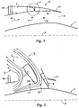
- the axis A of this turbojet engine is indicated in dashed lines on the Figures 1 and 2 , the upstream portion of the turbojet engine to the left of the figures, and the downstream portion to the right of these figures.
- the fixed internal structure 1 can technically be formed of composite material, and may have acoustic absorption characteristics intended to minimize the noise caused by the flow of cold air into the air stream cold 3.
- This cold air duct 3, substantially annular, is defined on the one hand by the internal fixed structure 1, and on the other hand by the peripheral part of the nacelle, conventionally comprising a thrust reverser device 5.
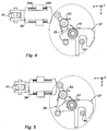
- such a thrust reverser device is movable between the configuration visible to the figure 1 , called “direct jet", in which the flow of cold air D circulates inside the vein 3 from upstream to downstream of the nacelle, and the visible configuration of the figure 2 so-called “reverse jet” in which the cold air flow I is rejected upstream of the nacelle, so as to exert a counter-thrust force.
- the "direct jet” configuration corresponds to the take-off and cruise flight situations of the aircraft, and the "reverse jet” situation corresponds to the landing situation of the aircraft, in which the aim is to minimize the distance braking.
- the thrust reverser device 5 is of the twin-door type.
- the upstream door 7 extends between the front frame 15, which is a fixed part of the nacelle, and the downstream door 9.
- This downstream door 9 extends between the upstream door 7 and the rear edge 17 of the nacelle.
- downstream door 9 comprises, on its outer upstream edge, a skin that advances to the outer downstream edge of the upstream door 7, thus ensuring the aerodynamic continuity of the outside of the nacelle.
- the two doors 7 and 9 are opened by pivoting them about their respective axes 11 and 13, so as to bring them to the end. to their visible position at the figure 2 .
- Another portion I2 of the cold air flow passes between the downstream edge 23 of the upstream door 7 and the fixed internal structure 1 of the nacelle 1, and is deflected by the downstream door 9 which completely closes the cold air vein 3.
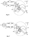
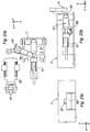
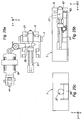
- the locking system 25 comprises a hook 27 pivotally mounted on the upstream door 7 about a Z direction axis.
- a locking latch 29 is itself pivotally mounted on the upstream door 7 about another axis Z direction.
- This locking latch 29 comprises a tail 31 terminated by a roller 33, this tail itself being capable of cooperating with a tail 35 of the hook 27, so as to prevent rotation of the latter.
- the latch 29 further comprises a head 37 capable of being pushed by a slider 39, slidably mounted on the underside of the upstream door 7, and connected by a hinge 40 to the end of the rod 41 of a hydraulic cylinder or electric 43, which cylinder makes it possible to move the upstream door 7 from its closed position ("direct jet” - figure 1 ) to its open position ("inverted jet” - figure 2 ).
- downstream door 9 is connected to the upstream door 7 by a pair of connecting rods 45a, 45b, arranged so that the opening / closing of the upstream door causes the opening / closing of the downstream door 9.
- the hook 27 cooperates with a pin 47 extending substantially in the direction Z, integral with the sliding cover, preferably surrounded by a roller 49.
- Spiral springs 51, 53 respectively centered on the axes of rotation of the hook 27 and the latch 29, tend to rotate respectively these two members in a clockwise and anti-clockwise manner.
- Belleville washers 54a, 54b provide elasticity and damping of the movements of the slider 39 relative to the upstream door 7. Without action of the jack 41 on the slider 39, the springs 54a and 54b are advantageously adjusted so that the spring 54b keeps the slide 39 away from the roller 37, to preserve the lock in case of rupture of a cylinder 41.
- the two upstream and downstream gates 9 connected to each other by the connecting rods 45a and 45b can pivot towards their open position shown in FIG. figure 2 , to return the cold air flow to the front of the nacelle, and thus perform the thrust reversal function.
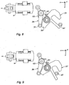
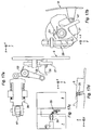
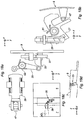
- the pin 47 eventually abuts against the hook 27 and pivots the latter clockwise, against the spiral spring ( Figures 8 and 9 ), until the tail 35 of the hook 27 passes through the tail 31 of the latch 29, allowing the latch to return to its initial position ( figure 10 ): it is then in the configuration where the hook 27 blocks any relative movement of the upstream and downstream doors 7 9, thus achieving a safety lock completely independent of other locking systems.
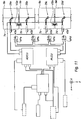
- each upstream door 7a, 7b, 7c, 7d is actuated by a respective cylinder 43a, 43b, 43c, 43d, which is capable of acting on a respective locking system 25a, 25b, 25c, 25d, arranged between the upstream doors 7a, 7b, 7c, 7d and downstream 9a, 9b, 9c, 9d, according to the explanation just given.
- these locking systems 25a, 25b, 25c, 25d are independent of two other locking systems, to guard against inadvertent opening of the twin doors.
- synchronization locks VSa and VSb are arranged between two adjacent upstream gates, on the one hand 7a, 7b and on the other hand 7c, 7d, preventing the opening of an upstream door as long as its adjacent upstream door n is itself not open: such a system is known per se, in particular from the patent FR 2 823 259 it will not be described in more detail here.
- control unit ADCU Actuator Directional Control Unit
- cylinders 43a, 43b, 43c, 43d is totally independent of the PLCU control unit, so that the three locking systems which have just been described (25, VP, VS) are completely independent of each other, thus guaranteeing the perfect safety of the locking of the doors of the thrust reverser in the "direct jet" position.
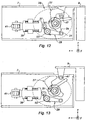
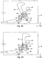
- the rotation of the hook 27 and the latch 29 is performed about axes substantially parallel to the axes of rotation 11 and 13 of the upstream and downstream doors 9 and 9, while in the previous embodiment, the axes of rotation of the hook 27 and the latch 29 were substantially perpendicular to the axes of rotation 11 and 13 of the doors 7 and 9, and the axis A of the nacelle.
- an extension 41 of the rod of the cylinder 43 has the effect of pushing on the head 37 of the latch 29, against the spiral spring 53, thus causing a rotation on the latch in the clockwise direction and releasing at the same the tail 35 of the hook 27, which can then pivot under the action of the spiral spring 51 in the counterclockwise direction, thus releasing the pin 47 secured to the downstream door 9 (see Figures 12 and 13 ).
- the tail 35 of the hook 27 extends in a direction substantially parallel to the median plane of this hook, that is to say in a direction substantially parallel to the axis A of the nacelle ( direction X).
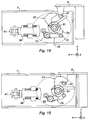
- the thrust exerted by the slider 39 on the head 37 of the latch 29, during the extension of the rod 41 of the jack 43 has the effect of disengaging the tail 31 of the latch 29 from the 35 of the hook 47 (see figures 16 and 17 ), thus releasing the pin 47, thus allowing the opening of the two twin doors 7 and 9.
- the movements of the bolt 27 are substantially in the direction X, that is to say, parallel to the axis A of the nacelle.
- This bolt 27 is capable of moving against the helical spring 51 under the action of the tail 31 of the latch 29, when it is actuated clockwise by the slide 39 mounted at the end of the rod 41 of the cylinder 43.
- This tail 31 may advantageously have a stirrup shape to surround the bolt 27.
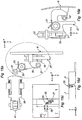
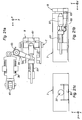
- Figures 20a, 20b, 20c corresponds to the "direct jet" configuration, in which it is desired that the upstream 7 and downstream 9 doors are locked relative to each other.
- the spring 51 is in full extension, so that the downstream end of the bolt 27 protrudes from the downstream edge of the door 7, and enters a keeper 61 (that is to say in a corresponding hole) formed on the upstream edge of the door 9.
- a stirrup 63 pivotally mounted about an axis substantially parallel to the axes of rotation 11 and 13 of the upstream and downstream gates 7 9, tilts about its axis under the action of a spiral spring 65 until it prevents the bolt 27 from coming out of the downstream edge of the upstream door 7.
- This embodiment differs from the first three embodiments described above in that the pin 47 is now mounted on the fixed structure of the thrust reverser, in the vicinity of the downstream edge of the downstream gate 9.
- the hook 27 is mounted on the downstream door 9, to the right of the pin 47, pivoting on an axis substantially parallel to the axes 11 and 13 of the two doors.
- a first latch 290 is pivotally mounted on the downstream flap 9, about an axis substantially parallel to the axes of rotation of the two upstream and downstream doors 7 and 9.
- the head 370 of this first latch 290 can be actuated by the slide 39 mounted at the end of the rod 41 of the jack 43.
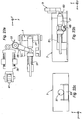
- the tail 310 of this first latch 290 cooperates with a cable 69 slidably mounted relative to the downstream door 9, and extending to a second latch 29, pivotally mounted about an axis substantially parallel to the axes 11 and 13 of the downstream door 9, against a spiral spring 53.
- the head 37 of this latch 29 cooperates with the cable 69, and the tail 31 of the latch 29 cooperates with a tail 35 of the hook 27, similarly to what has been exposed for the previous embodiments.
- the slider 39 exerts no effort on the head 370 of the first latch 290, so that the tail 31 of the second latch 29 blocks the tail 35 of the lock 27, preventing the latter to pivot, and therefore to disengage the pin 47 secured to the fixed structure of the nacelle: the downstream door 9, and thereby the upstream door 7 (through rods 45a and 45b) can not s 'open.
- the figures 29 show the hook 27 abutting against the pin 47, during an attempt to unintentional opening.
- the present invention provides a locking system of the two twin doors which is totally independent of other locking systems (primary lock and synchronized lock), without it being necessary to provide no additional specific control means.
Landscapes
- Engineering & Computer Science (AREA)
- Chemical & Material Sciences (AREA)
- Combustion & Propulsion (AREA)
- Mechanical Engineering (AREA)
- General Engineering & Computer Science (AREA)
- Power-Operated Mechanisms For Wings (AREA)
- Lock And Its Accessories (AREA)
- Wind Motors (AREA)
- Structures Of Non-Positive Displacement Pumps (AREA)
Claims (10)
- Schubumkehr für Triebwerksgondel eines Luftfahrzeugs, folgendes umfassend:- zumindest ein Doppeltürenpaar, eine Tür (7) stromaufwärts und eine Tür (9) stromabwärts umfassend, die durch zumindest eine Antriebsstange (45a, 45b) mit der stromaufwärts befindlichen Tür (7) verbunden ist, und- zumindest einen Zylinder zum Betätigen (43) der stromaufwärts befindlichen Tür (7), zwischen einer "Direktstrahl" Position, in der diese beiden Türen geschlossen sind, und einer "Umkehrstrahl" Position, in der diese beiden Türen offen und in der Lage sind, zumindest einen Teil (I) der kalten Luftströmung abzulenken, die imstande ist, im Inneren der Gondel zu zirkulieren, und- Mittel (25) zum Verriegeln/Freigeben der besagten stromaufwärts und stromabwärts befindlichen Türen zueinander nur durch die Betätigung des besagten Zylinders (43).
- Schubumkehr nach Anspruch 1, wobei die besagten Mittel zum Verriegeln/Freigeben folgendes umfassen:- einen Haken (27), der auf der besagten stromaufwärts befindlichen Tür (7) zwischen einer Position zum Verriegeln eines Stifts (47), der fest mit der besagten stromabwärts befindlichen Tür (9) verbunden ist, und einer Position zum Freigeben dieses Stifts (47) schwenkbar montiert ist,- elastische Mittel zum Rückholen (51) des besagten Hakens in seine Verriegelungsposition,- ein Schnappschloss (29), das auf der besagten stromaufwärts befindlichen Tür (7) zwischen einer Blockierposition, in der es den besagten Haken (27) in seiner Verriegelungsposition hält, und einer Freigabeposition schwenkbar montiert ist, in der es den Übergang des besagten Hakens (27) von seiner Verriegelungsposition in seine Freigabeposition zulässt,- elastische Mittel zum Rückholen (53) des besagten Schnappschlosses (29) in seine Blockierposition,- wobei der besagte Zylinder (43) und das besagte Schnappschloss (29) derart zueinander angeordnet sind, dass ein Ausfahren des besagten Zylinders (43) das besagte Schnappschloss (29) in dessen Freigabeposition schwenken lässt.
- Schubumkehr nach Anspruch 2, wobei der besagte Haken (27) und das besagte Schnappschloss (29) um Achsen schwenkbar montiert sind, die in etwa senkrecht zu den Drehachsen (11, 13) der stromaufwärts (7) und der stromabwärts (9) befindlichen Tür und zur Achse (A) der Gondel verlaufen.
- Schubumkehr nach Anspruch 2, wobei der besagte Haken (27) und das besagte Schnappschloss (29) um Achsen schwenkbar montiert sind, die in etwa parallel zu den Drehachsen (11) der stromaufwärts (7) und der stromabwärts (9) befindlichen Tür verlaufen.
- Schubumkehr nach Anspruch 2, wobei der besagte Haken (27) um eine Achse schwenkbar montiert ist, die in etwa parallel zur Achse (A) der Gondel verläuft, und das besagte Schnappschloss (29) um eine Achse schwenkbar montiert ist, die in etwa senkrecht zu den Drehachsen (11, 13) der stromaufwärts (7) und der stromabwärts (9) befindlichen Tür und zur Achse A der Gondel verläuft.
- Schubumkehr nach Anspruch 1, wobei die besagten Mittel zum Verriegeln/Freigeben folgendes umfassen:- einen Riegel (27), der in der besagten stromaufwärts befindlichen Tür (7) zwischen einer Verriegelungsposition einer Schließklappe (61), die in der besagten stromabwärts befindlichen Tür (9) ausgeführt ist, und einer Freigabeposition dieser Schließklappe (61) gleitend montiert ist,- elastische Mittel zum Rückholen (51) des besagten Riegels (27) in seine Verriegelungsposition,- ein Schnappschloss (29), das schwenkbar auf der besagten stromaufwärts befindlichen Tür (7) und mit dem besagten Riegel (27) zusammenwirkend montiert ist, damit eine Rotation dieses Schnappschlosses (29) dazu führt, diesen Riegel (27) zu verschieben,- wobei der besagte Zylinder (43) und die besagte Zuhaltung (29) derart zueinander angeordnet sind, dass ein Ausfahren des besagten Zylinders (43) das besagte Schnappschloss (29) in eine Richtung schwenken lassen, die zum Verschieben des besagten Riegels (27) in seine Freigabeposition führt.
- Schubumkehr nach Anspruch 6, wobei die besagten Mittel zum Verriegeln/Freigeben darüber hinaus einen Klemmbügel (63) umfassen, der um eine Achse schwenkbar auf der besagten stromaufwärts befindlichen Tür (7) montiert ist, die in etwa parallel zu den Drehachsen (11, 13) der besagten stromaufwärts befindlichen (7) und der stromabwärts befindlichen (9) Tür verläuft, und elastische Mittel (65) zum Rückholen dieses Klemmbügels in eine Position, in der er dafür sorgt, dass der besagte Riegel (27) in seiner Freigabeposition bleibt.
- Schubumkehr nach Anspruch 7, wobei die besagte stromabwärts befindliche Tür (9) ein Auflageorgan (67) umfasst, das in der Lage ist, den besagten Klemmbügel (63) entgegen die besagten elastischen Mittel (65) schwenken zu lassen.
- Schubumkehr nach Anspruch 1, wobei die besagten Mittel zum Verriegeln/Freigeben folgendes umfassen:- einen Haken (27), der auf der besagten stromabwärts befindlichen Tür (9) zwischen einer Position zum Verriegeln eines Stifts (47), der fest mit der festen Struktur der Umkehr verbunden ist, und einer Position zum Freigeben dieses Stifts (47) schwenkbar montiert ist,- elastische Mittel zum Rückholen (51) des besagten Hakens (27) in seine Verriegelungsposition,- ein Schnappschloss (29), das auf der besagten stromabwärts befindlichen Tür (9) zwischen einer Blockierposition, in der es den besagten Haken (27) in seiner Verriegelungsposition hält, und einer Freigabeposition schwenkbar montiert ist, in der es den Übergang des besagten Hakens (27) von seiner Verriegelungsposition in seine Freigabeposition zulässt,- elastische Mittel zum Rückholen (53) des besagten Schnappschlosses (29) in seine Blockierposition,- ein Kabel (69), von dem ein Ende gleitend auf der besagten stromaufwärts befindlichen Tür (7) montiert ist, und dessen anderes Ende mit dem besagten Schnappschloss (29) verbunden ist, sodass ein Ausfahren des besagten Zylinders (43) für ein Verschieben des besagten Kabels (69) im Verhältnis zur besagten stromaufwärts befindlichen Tür (7), und somit für die Rotation des besagten Schnappschlosses (29) in dessen Freigabeposition sorgt.
- Gondel, die mit einer Schubumkehr nach irgendeinem der vorherigen Ansprüche ausgestattet ist.
Applications Claiming Priority (2)
| Application Number | Priority Date | Filing Date | Title |
|---|---|---|---|
| FR1103406A FR2982324B1 (fr) | 2011-11-09 | 2011-11-09 | Inverseur de poussee a portes jumelles |
| PCT/FR2012/052409 WO2013068664A1 (fr) | 2011-11-09 | 2012-10-22 | Inverseur de poussée à portes jumelles |
Publications (2)
| Publication Number | Publication Date |
|---|---|
| EP2780574A1 EP2780574A1 (de) | 2014-09-24 |
| EP2780574B1 true EP2780574B1 (de) | 2016-03-23 |
Family
ID=47191973
Family Applications (1)
| Application Number | Title | Priority Date | Filing Date |
|---|---|---|---|
| EP12787791.8A Not-in-force EP2780574B1 (de) | 2011-11-09 | 2012-10-22 | Schubumkehrvorrichtung mit doppeltüren |
Country Status (8)
| Country | Link |
|---|---|
| US (1) | US20140245716A1 (de) |
| EP (1) | EP2780574B1 (de) |
| CN (1) | CN103917765B (de) |
| BR (1) | BR112014010136A2 (de) |
| CA (1) | CA2851891A1 (de) |
| FR (1) | FR2982324B1 (de) |
| RU (1) | RU2014122759A (de) |
| WO (1) | WO2013068664A1 (de) |
Families Citing this family (8)
| Publication number | Priority date | Publication date | Assignee | Title |
|---|---|---|---|---|
| FR2970521B1 (fr) * | 2011-01-17 | 2013-01-04 | Aircelle Sa | Inverseur de poussee pour turboreacteur d'aeronef a nombre de verrous reduit |
| FR3019857B1 (fr) * | 2014-04-11 | 2020-12-25 | Aircelle Sa | Inverseur de poussee de nacelle de turboreacteur comprenant une commande commune pour les capots mobiles et une tuyere variable |
| CN106378445A (zh) * | 2016-10-08 | 2017-02-08 | 江苏国能合金科技有限公司 | 一种非晶薄带设备车架锁定装置 |
| FR3065260B1 (fr) * | 2017-04-14 | 2020-10-09 | Safran Aircraft Engines | Systeme inverseur de poussee pour turboreacteur |
| EP3406859B1 (de) * | 2017-05-22 | 2023-03-01 | Goodrich Actuation Systems Limited | Tertiäres sperrsystem für schubumkehrer |
| US10612491B2 (en) * | 2017-09-25 | 2020-04-07 | Rohr, Inc. | Mounting device with pin actuator |
| US10907577B2 (en) * | 2017-10-23 | 2021-02-02 | Rohr, Inc. | Translating lock for pivot door thrust reverser |
| FR3086007B1 (fr) * | 2018-09-18 | 2020-09-04 | Safran Nacelles | Nacelle de turboreacteur avec un inverseur de poussee a grilles comprenant un secteur de commande des volets |
Family Cites Families (7)
| Publication number | Priority date | Publication date | Assignee | Title |
|---|---|---|---|---|
| US3739582A (en) * | 1972-04-13 | 1973-06-19 | Rohr Industries Inc | Thrust reversing apparatus |
| FR2722534B1 (fr) * | 1994-07-13 | 1996-08-14 | Hispano Suiza Sa | Inverseur de poussee de turboreacteur double flux, a obstacles externes |
| FR2754565B1 (fr) * | 1996-10-10 | 1999-01-08 | Hispano Suiza Sa | Inverseur de poussee a portes a debit de fuite controle |
| FR2764341B1 (fr) * | 1997-06-05 | 1999-07-16 | Hispano Suiza Sa | Inverseur de poussee de turboreacteur a portes formant ecopes associees a un deflecteur mobile |
| FR2823259B1 (fr) | 2001-04-05 | 2003-06-27 | Hispano Suiza Sa | Systeme de verrouillage synchronise des portes d'un inverseur de poussee |
| US7146796B2 (en) * | 2003-09-05 | 2006-12-12 | The Nordam Group, Inc. | Nested latch thrust reverser |
| FR2926112A1 (fr) * | 2008-01-08 | 2009-07-10 | Aircelle Sa | Inverseur de poussee a portes pour turboreacteur |
-
2011
- 2011-11-09 FR FR1103406A patent/FR2982324B1/fr not_active Expired - Fee Related
-
2012
- 2012-10-22 RU RU2014122759/06A patent/RU2014122759A/ru not_active Application Discontinuation
- 2012-10-22 WO PCT/FR2012/052409 patent/WO2013068664A1/fr not_active Ceased
- 2012-10-22 EP EP12787791.8A patent/EP2780574B1/de not_active Not-in-force
- 2012-10-22 CN CN201280055100.3A patent/CN103917765B/zh not_active Expired - Fee Related
- 2012-10-22 BR BR112014010136A patent/BR112014010136A2/pt not_active IP Right Cessation
- 2012-10-22 CA CA2851891A patent/CA2851891A1/fr not_active Abandoned
-
2014
- 2014-05-09 US US14/273,778 patent/US20140245716A1/en not_active Abandoned
Non-Patent Citations (1)
| Title |
|---|
| None * |
Also Published As
| Publication number | Publication date |
|---|---|
| BR112014010136A2 (pt) | 2017-04-25 |
| US20140245716A1 (en) | 2014-09-04 |
| WO2013068664A1 (fr) | 2013-05-16 |
| CN103917765B (zh) | 2016-03-30 |
| EP2780574A1 (de) | 2014-09-24 |
| CA2851891A1 (fr) | 2013-05-16 |
| FR2982324B1 (fr) | 2013-11-15 |
| CN103917765A (zh) | 2014-07-09 |
| FR2982324A1 (fr) | 2013-05-10 |
| RU2014122759A (ru) | 2015-12-20 |
Similar Documents
| Publication | Publication Date | Title |
|---|---|---|
| EP2780574B1 (de) | Schubumkehrvorrichtung mit doppeltüren | |
| EP3581742B1 (de) | Flächenbündiger türgriff und verfahren zum betrieb davon | |
| EP0869272B1 (de) | Schubumkehrvorrichtung, die auch bei eventueller Beschädigung gegen ungewolltes Oeffnen gesichert ist | |
| EP2665911B1 (de) | Schubumkehrvorrichtung für einen flugzeug-turbodüsenmotor mit einer geringeren anzahl von riegeln | |
| EP1260696B1 (de) | Synchronisierte Verriegelungsvorrichtung für die Klappen einer Schubumkehrvorrichtung | |
| CA2678308A1 (fr) | Verin a dispositif de verrouillage integre | |
| EP0834651A1 (de) | Methode und Einrichtung um die Klappen einer Schubumkehrvorrichtung zu schliessen | |
| CA2379192C (fr) | Systeme de verrouillage de secours pour porte d'inverseur de poussee | |
| CA2243057A1 (fr) | Inverseur de poussee a visualisation de verrouillage | |
| EP3191368B1 (de) | Antriebseinheit für ein flugzeug und verfahren zur öffnung einer beweglichen haube der besagten antriebseinheit | |
| WO2008139048A2 (fr) | Nacelle pour turboreacteur equipee d'un systeme d'inversion de poussee a une seule porte | |
| CA2696231A1 (fr) | Inverseur de poussee avec systeme de freinage des actionneurs | |
| FR3012089A1 (fr) | Dispositif de blocage en position d'un element rabattable pour un siege de vehicule | |
| EP2190741B1 (de) | Triebwerksgondel mit dämpfern für halbschalen | |
| EP3584157B1 (de) | Verfahren zum bewegen von frachtraumtüren des fahrwerks eines luftfahrzeugs | |
| WO2015150707A1 (fr) | Système de verrouillage d'un inverseur de poussée à portes, comportant des verrous pour une position d'ouverture intermédiaire | |
| EP2178756B1 (de) | Kopplungsvorrichtung zur verbindung der beiden abdeckungshälften einer flugzeugtriebwerksgondel sowie mit einer solchen vorrichtung ausgestattete gondel | |
| CA2681354A1 (fr) | Dispositif de variation de section de tuyere secondaire associe a un inverseur a portes a dispositif de lissage de veine | |
| WO2015140450A1 (fr) | Dispositif de verrouillage pour un inverseur de poussée à porte | |
| WO2024115363A1 (fr) | Interface entre un mécanisme principal d'ouverture de porte d'aéronef et un système de détection et d'enregistrement d'une ouverture de porte par l'extérieur | |
| FR2953491A1 (fr) | Nacelle d'aeronef incorporant un dispositif pour proteger un volet d'acces a un systeme de verrouillage | |
| WO2019081865A1 (fr) | Inverseur de poussée avec systeme verrouillable et deverrouillable sous charge | |
| FR2710368A1 (fr) | Turboréacteur à double flux à porte pivotante d'inversion de poussée équipée d'un système de verrouillage de sécurité. |
Legal Events
| Date | Code | Title | Description |
|---|---|---|---|
| PUAI | Public reference made under article 153(3) epc to a published international application that has entered the european phase |
Free format text: ORIGINAL CODE: 0009012 |
|
| 17P | Request for examination filed |
Effective date: 20140520 |
|
| AK | Designated contracting states |
Kind code of ref document: A1 Designated state(s): AL AT BE BG CH CY CZ DE DK EE ES FI FR GB GR HR HU IE IS IT LI LT LU LV MC MK MT NL NO PL PT RO RS SE SI SK SM TR |
|
| DAX | Request for extension of the european patent (deleted) | ||
| GRAP | Despatch of communication of intention to grant a patent |
Free format text: ORIGINAL CODE: EPIDOSNIGR1 |
|
| INTG | Intention to grant announced |
Effective date: 20150922 |
|
| GRAS | Grant fee paid |
Free format text: ORIGINAL CODE: EPIDOSNIGR3 |
|
| GRAA | (expected) grant |
Free format text: ORIGINAL CODE: 0009210 |
|
| INTG | Intention to grant announced |
Effective date: 20160127 |
|
| AK | Designated contracting states |
Kind code of ref document: B1 Designated state(s): AL AT BE BG CH CY CZ DE DK EE ES FI FR GB GR HR HU IE IS IT LI LT LU LV MC MK MT NL NO PL PT RO RS SE SI SK SM TR |
|
| REG | Reference to a national code |
Ref country code: GB Ref legal event code: FG4D Free format text: NOT ENGLISH |
|
| REG | Reference to a national code |
Ref country code: CH Ref legal event code: EP |
|
| REG | Reference to a national code |
Ref country code: AT Ref legal event code: REF Ref document number: 783418 Country of ref document: AT Kind code of ref document: T Effective date: 20160415 |
|
| REG | Reference to a national code |
Ref country code: IE Ref legal event code: FG4D Free format text: LANGUAGE OF EP DOCUMENT: FRENCH |
|
| REG | Reference to a national code |
Ref country code: DE Ref legal event code: R096 Ref document number: 602012016029 Country of ref document: DE |
|
| REG | Reference to a national code |
Ref country code: LT Ref legal event code: MG4D |
|
| REG | Reference to a national code |
Ref country code: NL Ref legal event code: MP Effective date: 20160323 |
|
| PG25 | Lapsed in a contracting state [announced via postgrant information from national office to epo] |
Ref country code: HR Free format text: LAPSE BECAUSE OF FAILURE TO SUBMIT A TRANSLATION OF THE DESCRIPTION OR TO PAY THE FEE WITHIN THE PRESCRIBED TIME-LIMIT Effective date: 20160323 Ref country code: FI Free format text: LAPSE BECAUSE OF FAILURE TO SUBMIT A TRANSLATION OF THE DESCRIPTION OR TO PAY THE FEE WITHIN THE PRESCRIBED TIME-LIMIT Effective date: 20160323 Ref country code: NO Free format text: LAPSE BECAUSE OF FAILURE TO SUBMIT A TRANSLATION OF THE DESCRIPTION OR TO PAY THE FEE WITHIN THE PRESCRIBED TIME-LIMIT Effective date: 20160623 Ref country code: GR Free format text: LAPSE BECAUSE OF FAILURE TO SUBMIT A TRANSLATION OF THE DESCRIPTION OR TO PAY THE FEE WITHIN THE PRESCRIBED TIME-LIMIT Effective date: 20160624 |
|
| REG | Reference to a national code |
Ref country code: AT Ref legal event code: MK05 Ref document number: 783418 Country of ref document: AT Kind code of ref document: T Effective date: 20160323 |
|
| PG25 | Lapsed in a contracting state [announced via postgrant information from national office to epo] |
Ref country code: NL Free format text: LAPSE BECAUSE OF FAILURE TO SUBMIT A TRANSLATION OF THE DESCRIPTION OR TO PAY THE FEE WITHIN THE PRESCRIBED TIME-LIMIT Effective date: 20160323 Ref country code: LV Free format text: LAPSE BECAUSE OF FAILURE TO SUBMIT A TRANSLATION OF THE DESCRIPTION OR TO PAY THE FEE WITHIN THE PRESCRIBED TIME-LIMIT Effective date: 20160323 Ref country code: RS Free format text: LAPSE BECAUSE OF FAILURE TO SUBMIT A TRANSLATION OF THE DESCRIPTION OR TO PAY THE FEE WITHIN THE PRESCRIBED TIME-LIMIT Effective date: 20160323 Ref country code: LT Free format text: LAPSE BECAUSE OF FAILURE TO SUBMIT A TRANSLATION OF THE DESCRIPTION OR TO PAY THE FEE WITHIN THE PRESCRIBED TIME-LIMIT Effective date: 20160323 Ref country code: SE Free format text: LAPSE BECAUSE OF FAILURE TO SUBMIT A TRANSLATION OF THE DESCRIPTION OR TO PAY THE FEE WITHIN THE PRESCRIBED TIME-LIMIT Effective date: 20160323 |
|
| PG25 | Lapsed in a contracting state [announced via postgrant information from national office to epo] |
Ref country code: EE Free format text: LAPSE BECAUSE OF FAILURE TO SUBMIT A TRANSLATION OF THE DESCRIPTION OR TO PAY THE FEE WITHIN THE PRESCRIBED TIME-LIMIT Effective date: 20160323 Ref country code: IS Free format text: LAPSE BECAUSE OF FAILURE TO SUBMIT A TRANSLATION OF THE DESCRIPTION OR TO PAY THE FEE WITHIN THE PRESCRIBED TIME-LIMIT Effective date: 20160723 Ref country code: PL Free format text: LAPSE BECAUSE OF FAILURE TO SUBMIT A TRANSLATION OF THE DESCRIPTION OR TO PAY THE FEE WITHIN THE PRESCRIBED TIME-LIMIT Effective date: 20160323 |
|
| PG25 | Lapsed in a contracting state [announced via postgrant information from national office to epo] |
Ref country code: PT Free format text: LAPSE BECAUSE OF FAILURE TO SUBMIT A TRANSLATION OF THE DESCRIPTION OR TO PAY THE FEE WITHIN THE PRESCRIBED TIME-LIMIT Effective date: 20160725 Ref country code: SM Free format text: LAPSE BECAUSE OF FAILURE TO SUBMIT A TRANSLATION OF THE DESCRIPTION OR TO PAY THE FEE WITHIN THE PRESCRIBED TIME-LIMIT Effective date: 20160323 Ref country code: ES Free format text: LAPSE BECAUSE OF FAILURE TO SUBMIT A TRANSLATION OF THE DESCRIPTION OR TO PAY THE FEE WITHIN THE PRESCRIBED TIME-LIMIT Effective date: 20160323 Ref country code: SK Free format text: LAPSE BECAUSE OF FAILURE TO SUBMIT A TRANSLATION OF THE DESCRIPTION OR TO PAY THE FEE WITHIN THE PRESCRIBED TIME-LIMIT Effective date: 20160323 Ref country code: AT Free format text: LAPSE BECAUSE OF FAILURE TO SUBMIT A TRANSLATION OF THE DESCRIPTION OR TO PAY THE FEE WITHIN THE PRESCRIBED TIME-LIMIT Effective date: 20160323 Ref country code: RO Free format text: LAPSE BECAUSE OF FAILURE TO SUBMIT A TRANSLATION OF THE DESCRIPTION OR TO PAY THE FEE WITHIN THE PRESCRIBED TIME-LIMIT Effective date: 20160323 Ref country code: CZ Free format text: LAPSE BECAUSE OF FAILURE TO SUBMIT A TRANSLATION OF THE DESCRIPTION OR TO PAY THE FEE WITHIN THE PRESCRIBED TIME-LIMIT Effective date: 20160323 |
|
| PG25 | Lapsed in a contracting state [announced via postgrant information from national office to epo] |
Ref country code: IT Free format text: LAPSE BECAUSE OF FAILURE TO SUBMIT A TRANSLATION OF THE DESCRIPTION OR TO PAY THE FEE WITHIN THE PRESCRIBED TIME-LIMIT Effective date: 20160323 |
|
| REG | Reference to a national code |
Ref country code: DE Ref legal event code: R097 Ref document number: 602012016029 Country of ref document: DE |
|
| PLBE | No opposition filed within time limit |
Free format text: ORIGINAL CODE: 0009261 |
|
| STAA | Information on the status of an ep patent application or granted ep patent |
Free format text: STATUS: NO OPPOSITION FILED WITHIN TIME LIMIT |
|
| PG25 | Lapsed in a contracting state [announced via postgrant information from national office to epo] |
Ref country code: DK Free format text: LAPSE BECAUSE OF FAILURE TO SUBMIT A TRANSLATION OF THE DESCRIPTION OR TO PAY THE FEE WITHIN THE PRESCRIBED TIME-LIMIT Effective date: 20160323 |
|
| PG25 | Lapsed in a contracting state [announced via postgrant information from national office to epo] |
Ref country code: BE Free format text: LAPSE BECAUSE OF NON-PAYMENT OF DUE FEES Effective date: 20161031 Ref country code: BG Free format text: LAPSE BECAUSE OF FAILURE TO SUBMIT A TRANSLATION OF THE DESCRIPTION OR TO PAY THE FEE WITHIN THE PRESCRIBED TIME-LIMIT Effective date: 20160623 |
|
| 26N | No opposition filed |
Effective date: 20170102 |
|
| REG | Reference to a national code |
Ref country code: DE Ref legal event code: R119 Ref document number: 602012016029 Country of ref document: DE |
|
| PG25 | Lapsed in a contracting state [announced via postgrant information from national office to epo] |
Ref country code: SI Free format text: LAPSE BECAUSE OF FAILURE TO SUBMIT A TRANSLATION OF THE DESCRIPTION OR TO PAY THE FEE WITHIN THE PRESCRIBED TIME-LIMIT Effective date: 20160323 |
|
| REG | Reference to a national code |
Ref country code: CH Ref legal event code: PL |
|
| GBPC | Gb: european patent ceased through non-payment of renewal fee |
Effective date: 20161022 |
|
| REG | Reference to a national code |
Ref country code: IE Ref legal event code: MM4A |
|
| REG | Reference to a national code |
Ref country code: FR Ref legal event code: ST Effective date: 20170630 |
|
| PG25 | Lapsed in a contracting state [announced via postgrant information from national office to epo] |
Ref country code: GB Free format text: LAPSE BECAUSE OF NON-PAYMENT OF DUE FEES Effective date: 20161022 Ref country code: CH Free format text: LAPSE BECAUSE OF NON-PAYMENT OF DUE FEES Effective date: 20161031 Ref country code: DE Free format text: LAPSE BECAUSE OF NON-PAYMENT OF DUE FEES Effective date: 20170503 Ref country code: FR Free format text: LAPSE BECAUSE OF NON-PAYMENT OF DUE FEES Effective date: 20161102 Ref country code: LI Free format text: LAPSE BECAUSE OF NON-PAYMENT OF DUE FEES Effective date: 20161031 |
|
| PG25 | Lapsed in a contracting state [announced via postgrant information from national office to epo] |
Ref country code: LU Free format text: LAPSE BECAUSE OF NON-PAYMENT OF DUE FEES Effective date: 20161022 |
|
| PG25 | Lapsed in a contracting state [announced via postgrant information from national office to epo] |
Ref country code: IE Free format text: LAPSE BECAUSE OF NON-PAYMENT OF DUE FEES Effective date: 20161022 |
|
| REG | Reference to a national code |
Ref country code: BE Ref legal event code: MM Effective date: 20161031 |
|
| PG25 | Lapsed in a contracting state [announced via postgrant information from national office to epo] |
Ref country code: HU Free format text: LAPSE BECAUSE OF FAILURE TO SUBMIT A TRANSLATION OF THE DESCRIPTION OR TO PAY THE FEE WITHIN THE PRESCRIBED TIME-LIMIT; INVALID AB INITIO Effective date: 20121022 |
|
| PG25 | Lapsed in a contracting state [announced via postgrant information from national office to epo] |
Ref country code: MC Free format text: LAPSE BECAUSE OF FAILURE TO SUBMIT A TRANSLATION OF THE DESCRIPTION OR TO PAY THE FEE WITHIN THE PRESCRIBED TIME-LIMIT Effective date: 20160323 Ref country code: MT Free format text: LAPSE BECAUSE OF FAILURE TO SUBMIT A TRANSLATION OF THE DESCRIPTION OR TO PAY THE FEE WITHIN THE PRESCRIBED TIME-LIMIT Effective date: 20160323 Ref country code: MK Free format text: LAPSE BECAUSE OF FAILURE TO SUBMIT A TRANSLATION OF THE DESCRIPTION OR TO PAY THE FEE WITHIN THE PRESCRIBED TIME-LIMIT Effective date: 20160323 Ref country code: CY Free format text: LAPSE BECAUSE OF FAILURE TO SUBMIT A TRANSLATION OF THE DESCRIPTION OR TO PAY THE FEE WITHIN THE PRESCRIBED TIME-LIMIT Effective date: 20160323 |
|
| PG25 | Lapsed in a contracting state [announced via postgrant information from national office to epo] |
Ref country code: AL Free format text: LAPSE BECAUSE OF FAILURE TO SUBMIT A TRANSLATION OF THE DESCRIPTION OR TO PAY THE FEE WITHIN THE PRESCRIBED TIME-LIMIT Effective date: 20160323 Ref country code: TR Free format text: LAPSE BECAUSE OF FAILURE TO SUBMIT A TRANSLATION OF THE DESCRIPTION OR TO PAY THE FEE WITHIN THE PRESCRIBED TIME-LIMIT Effective date: 20160323 |