EP2780607B1 - Luftfeder - Google Patents
Luftfeder Download PDFInfo
- Publication number
- EP2780607B1 EP2780607B1 EP12786950.1A EP12786950A EP2780607B1 EP 2780607 B1 EP2780607 B1 EP 2780607B1 EP 12786950 A EP12786950 A EP 12786950A EP 2780607 B1 EP2780607 B1 EP 2780607B1
- Authority
- EP
- European Patent Office
- Prior art keywords
- air spring
- component
- piston
- piston part
- rolling
- Prior art date
- Legal status (The legal status is an assumption and is not a legal conclusion. Google has not performed a legal analysis and makes no representation as to the accuracy of the status listed.)
- Active
Links
Images




Classifications
-
- B—PERFORMING OPERATIONS; TRANSPORTING
- B60—VEHICLES IN GENERAL
- B60G—VEHICLE SUSPENSION ARRANGEMENTS
- B60G11/00—Resilient suspensions characterised by arrangement, location or kind of springs
- B60G11/32—Resilient suspensions characterised by arrangement, location or kind of springs having springs of different kinds
- B60G11/48—Resilient suspensions characterised by arrangement, location or kind of springs having springs of different kinds not including leaf springs
- B60G11/62—Resilient suspensions characterised by arrangement, location or kind of springs having springs of different kinds not including leaf springs having both rubber springs and fluid springs
-
- F—MECHANICAL ENGINEERING; LIGHTING; HEATING; WEAPONS; BLASTING
- F16—ENGINEERING ELEMENTS AND UNITS; GENERAL MEASURES FOR PRODUCING AND MAINTAINING EFFECTIVE FUNCTIONING OF MACHINES OR INSTALLATIONS; THERMAL INSULATION IN GENERAL
- F16F—SPRINGS; SHOCK-ABSORBERS; MEANS FOR DAMPING VIBRATION
- F16F9/00—Springs, vibration-dampers, shock-absorbers, or similarly-constructed movement-dampers using a fluid or the equivalent as damping medium
- F16F9/02—Springs, vibration-dampers, shock-absorbers, or similarly-constructed movement-dampers using a fluid or the equivalent as damping medium using gas only or vacuum
- F16F9/04—Springs, vibration-dampers, shock-absorbers, or similarly-constructed movement-dampers using a fluid or the equivalent as damping medium using gas only or vacuum in a chamber with a flexible wall
- F16F9/0454—Springs, vibration-dampers, shock-absorbers, or similarly-constructed movement-dampers using a fluid or the equivalent as damping medium using gas only or vacuum in a chamber with a flexible wall characterised by the assembling method or by the mounting arrangement, e.g. mounting of the membrane
-
- B—PERFORMING OPERATIONS; TRANSPORTING
- B60—VEHICLES IN GENERAL
- B60G—VEHICLE SUSPENSION ARRANGEMENTS
- B60G17/00—Resilient suspensions having means for adjusting the spring or vibration-damper characteristics, for regulating the distance between a supporting surface and a sprung part of vehicle or for locking suspension during use to meet varying vehicular or surface conditions, e.g. due to speed or load
- B60G17/02—Spring characteristics, e.g. mechanical springs and mechanical adjusting means
- B60G17/04—Spring characteristics, e.g. mechanical springs and mechanical adjusting means fluid spring characteristics
- B60G17/052—Pneumatic spring characteristics
- B60G17/0521—Pneumatic spring characteristics the spring having a flexible wall
-
- F—MECHANICAL ENGINEERING; LIGHTING; HEATING; WEAPONS; BLASTING
- F16—ENGINEERING ELEMENTS AND UNITS; GENERAL MEASURES FOR PRODUCING AND MAINTAINING EFFECTIVE FUNCTIONING OF MACHINES OR INSTALLATIONS; THERMAL INSULATION IN GENERAL
- F16F—SPRINGS; SHOCK-ABSORBERS; MEANS FOR DAMPING VIBRATION
- F16F9/00—Springs, vibration-dampers, shock-absorbers, or similarly-constructed movement-dampers using a fluid or the equivalent as damping medium
- F16F9/02—Springs, vibration-dampers, shock-absorbers, or similarly-constructed movement-dampers using a fluid or the equivalent as damping medium using gas only or vacuum
- F16F9/04—Springs, vibration-dampers, shock-absorbers, or similarly-constructed movement-dampers using a fluid or the equivalent as damping medium using gas only or vacuum in a chamber with a flexible wall
- F16F9/05—Springs, vibration-dampers, shock-absorbers, or similarly-constructed movement-dampers using a fluid or the equivalent as damping medium using gas only or vacuum in a chamber with a flexible wall the flexible wall being of the rolling diaphragm type
- F16F9/057—Springs, vibration-dampers, shock-absorbers, or similarly-constructed movement-dampers using a fluid or the equivalent as damping medium using gas only or vacuum in a chamber with a flexible wall the flexible wall being of the rolling diaphragm type characterised by the piston
Definitions
- the invention relates to an air spring for vehicles with a between an air spring cover and a Heilfederabrollkolben airtight clamped air spring bellows made of elastomeric material which limits a compressed air filled working space with the air spring cover and the Heilfederabrollkolben and rolls to form a rolled fold on Lucasfederabrollkolben and forming a second fold is attached to the air spring cover, and with an elastomeric element, which is provided as an anti-roughness bearing.
- Air springs which are clamped between the chassis and the vehicle body and having an air spring bellows, which in turn is mounted between an air spring cover and a rolling piston, are known in a variety of designs.
- the air spring is in operation under an internal overpressure.
- the air spring bellows rolls under load and during spring movements to form a rolling fold on the outer contour of the concentric air spring piston / rolling piston from.
- Such air spring is often used in road or Rail vehicles used to achieve a comfortable suspension.
- Harshness is understood to mean a superimposed, rough and hard suspension behavior with vibrations of higher frequency and lower amplitude, which depends on the applied working pressure and the bearings between the components and the vehicle body in the case of air springs or air spring and damper units.
- An air spring with anti-Harshnesslager is for example from the DE 102010017227 A1 known, wherein the bearing is provided as an elastomer element between a Deckelober- and a lower lid part.
- the invention is therefore based on the object to provide an air spring for vehicles, which optimize an optimized space for a free-standing air spring, especially in the overhead position with anti-Harshnesslager.
- the efficiency of the warehouse should be optimized in terms of ride comfort.
- the elastomer element is arranged between a first piston part and a second piston part of the air spring roll piston which is coaxial therewith, wherein the rolling surface for the air spring bellows is provided on the first piston part and the air spring bellows is fastened by means of a clamping element and the second piston part adjoins a mounting surface of a vehicle body is mountable. Due to the positioning of the anti-roughness bearing in Vietnamesefederabrollkolben a compared to known air springs in over-head position significantly shortened axial height of the air spring can be achieved. Furthermore, the arrangement of the anti-roughness bearing in Heilfederabrollkolben by the proximity to the vehicle body allows a more direct comfort effect.
- the elastomer element as anti-roughness bearing is provided according to the invention of rubber and vulcanized between the two piston parts, whereby a simple production is achieved.
- the first piston part is formed in two parts with a first and a second component, the first component being provided for fastening the air spring bellows and the rolling surface being arranged on the second component.
- the second component has a radially inwardly directed shoulder, which for attachment to the first Component engages in a recess on an outer side of the first component, whereby the rolling contour of the piston can be replaced in a simple manner.
- the elastomer element is made of rubber and vulcanized between two ring elements, which are arranged between the second piston part and the first component of the first piston part.
- the second piston part can be designed in three parts, the switching valve being arranged between a first component provided as a partition and a second part second component is arranged, which are sealed together, and wherein a third component, which is connected to the second component, is provided for attachment to the mounting surface of the vehicle body.
- the first and the second component can be sealed together by means of a threaded connection.
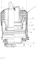
- the Fig.1 shows a first embodiment of an air spring 1 in the installed state in a vehicle while Fig. 2 an enlarged Luftfederabrollkolben 2 in the Fig. 1 shown air spring 1 shows.
- the air spring 1 Between an air spring cover 3 and the Heilfederabrollkolben 2, the air spring 1 an air-tight clamped air spring bellows 4 made of elastomeric material which limits a filled with compressed air working space 5 with the air spring cover 3 and the Heilfederabrollkolben 2.
- the air spring bellows 4 rolls off to form a rolled fold 6 on Luftfederabrollkolben 2 and is attached to form a second fold 7 on the air spring cover 2.
- anti-roughness bearing As anti-roughness bearing (anti-Harshnesslager) is a Elastomer element 8 is provided which improves the spring comfort of the air spring 1 in the vehicle. Harshness is understood to mean a superimposed, rough and hard suspension behavior with vibrations of higher frequency and lower amplitude, which depends on the applied working pressure and the bearings between the components and the vehicle body in the case of air springs or air spring and damper units.
- the elastomer element 8 is arranged between a first piston part 11 and a second piston part 12 of the Lucasfederabrollkolben 2 coaxial therewith.
- the elastomer element 8 as anti-roughness bearing is provided in this embodiment of rubber and vulcanized between the two piston parts 11, 2, which requires a simple production.
- the rolling surface for the air spring bellows 4 on the provided first piston member 11 and the air spring bellows 4 is fixed by means of a clamping member 13 to the first piston member 11.
- the second piston part 12 can be mounted on a mounting surface of the vehicle body 9.
- Fig. 3 shows a comparison between a known air spring in the left half and the non-inventive air spring 1 in over-head position in the right half. It can be clearly seen that a shortening of the axial height of the air spring 1 by an amount x can be achieved by the positioning of the anti-roughness bearing in Luftfederabrollkolben 2. Furthermore, the arrangement of the anti-roughness bearing in Vietnamesefederabrollkolben 2 due to the closer positioning to the vehicle body 9 allows a more direct comfort effect.
- Fig. 4 is a Lucasfederabrollkolben 14 of a second embodiment of an air spring according to the invention can be seen.
- a first piston part 15 of Vietnamesefederabrollkolbens 14 is in two parts with a first and a second component 17, 18 is formed.
- the first component 17 is provided for fixing the air spring bellows 4 and on the second component 18, the rolling surface is arranged.
- the second component 18 For attachment to the first component 17, the second component 18 has a radially inwardly directed shoulder 19, which engages in a recess 20 on an outer side of the first component 17.
- Fig. 4 it can be seen that the intended as anti-harshness bearing (anti-Harshnesslager) elastomeric element 21 is formed of rubber and between two ring elements 22, 23 is vulcanized, which between the second piston part 16 and the first component 17 of the first piston part 15 are arranged and pressed into this.
- anti-harshness bearing (anti-Harshnesslager) elastomeric element 21 is formed of rubber and between two ring elements 22, 23 is vulcanized, which between the second piston part 16 and the first component 17 of the first piston part 15 are arranged and pressed into this.
- both the anti-roughness bearing and the rolling contour of the Luftfederabrollkolbens 14 can be exchanged in a simple manner, whereby the identifier of the air spring can be changed in the context of a driving mood.
- the air spring may have at least one further working space 25, as shown in FIG Fig. 5 , which shows a Lucasfederabrollkolben 24 of a third embodiment with a first and a second piston part 27,28.
- the further working space 25 is separated from the working space 5 by means of a partition wall and a switching valve 26.
- the second piston part 28 is formed in three parts, wherein the switching valve 26 between a first, provided as a partition wall member 29 and a second component 30 is arranged, which are sealed together.
- a third component 31, which in turn is connected to the second component 30, is provided for attachment to the mounting surface of the vehicle body 9 and allows easy removal of a connecting cable 32 of the switching valve 26th
- first and the second component 29,39 are sealed together by means of a threaded connection, this connection can also be done by means of other types of connection.
Landscapes
- Engineering & Computer Science (AREA)
- General Engineering & Computer Science (AREA)
- Mechanical Engineering (AREA)
- Fluid-Damping Devices (AREA)
- Vehicle Body Suspensions (AREA)
- Vibration Prevention Devices (AREA)
Description
- Die Erfindung betrifft eine Luftfeder für Fahrzeuge mit einem zwischen einem Luftfederdeckel und einem Luftfederabrollkolben luftdicht eingespannten Luftfederbalg aus elastomerem Material, welcher mit dem Luftfederdeckel und dem Luftfederabrollkolben einen mit Druckluft gefüllten Arbeitsraum begrenzt und der unter Ausbildung einer Rollfalte am Luftfederabrollkolben abrollt und unter Ausbildung einer zweiten Falte am Luftfederdeckel befestigt ist, sowie mit einem Elastomerelement, welches als Anti-Rauhigkeitslager vorgesehen ist.
- Luftfedern, die zwischen Fahrwerk und Fahrzeugkarosserie eingespannt sind und einen Luftfederbalg aufweisen, der wiederum zwischen einem Luftfederdeckel und einem Abrollkolben befestigt ist, sind in eine Vielzahl von Ausführungen bekannt. Die Luftfeder steht im Betrieb unter einem inneren Überdruck. Der Luftfederbalg rollt unter Last und bei Federbewegungen unter Bildung einer Rollfalte auf der Außenkontur des konzentrischen Luftfederkolbens/Abrollkolbens ab. Eine derartige Luftfeder wird häufig in Straßen- oder Schienenfahrzeugen eingesetzt, um eine komfortable Federung zu erreichen.
- Zunehmend werden sogenannte "Anti-Harshnesslager" (Anti-Rauhigkeitslager) verlangt, um den Federkomfort der Luftfeder im Fahrzeug zu verbessern. Als Harshness wird ein überlagertes, raues und hartes Federungsverhalten bei Schwingungen höherer Frequenz und geringerer Amplitude verstanden, welches bei Luftfedern bzw. bei Luftfeder- und Dämpfereinheiten von dem anliegenden Arbeitsdruck sowie den Lagerungen zwischen den Bauteilen und der Fahrzeugkarosserie abhängig ist.
- Eine Luftfeder mit Anti-Harshnesslager ist beispielsweise aus der
DE 102010017227 A1 bekannt, wobei das Lager als Elastomerelement zwischen einem Deckelober- und einem Deckelunterteil vorgesehen ist. - Insbesondere bei modernen Fahrzeugen, bei welchen es aufgrund des vorhandenen geringen Bauraumes oft nötig ist, die Luftfeder ohne integrierte Dämpfer in Über-Kopf-Lage einzubauen, schränkt diese Anordnung den axialen Bauraum erheblich ein oder das Elastomerelement ist nicht optimal zum wirksamen Durchmesser der Luftfeder ausgerichtet.
- Das Dokument
EP 1 614 928 A1 , welches als der nächstliegende Stand der Technik angesehen wird, offenbart die Merkmale des Oberbegriffs des Anspruchs 1. - Der Erfindung liegt daher die Aufgabe zugrunde, eine Luftfeder für Fahrzeuge bereitzustellen, welche einen optimierten Bauraum für eine freistehende Luftfeder insbesondere in Über-Kopf-Lage mit Anti-Harshnesslager zu optimieren. Zusätzlich soll die Wirksamkeit des Lagers bezüglich des Fahrkomforts optimiert werden.
- Die Aufgaben werden erfindungsgemäß dadurch gelöst, dass das Elastomerelement zwischen einem ersten Kolbenteil und einem dazu koaxialen zweiten Kolbenteil des Luftfederabrollkolben angeordnet ist, wobei an dem ersten Kolbenteil die Abrollfläche für den Luftfederbalg vorgesehen und der Luftfederbalg mittels eines Klemmelements befestigt ist und wobei das zweite Kolbenteil an einer Montagefläche einer Fahrzeugkarosserie montierbar ist. Durch die Positionierung des Anti-Rauhigkeitslagers im Luftfederabrollkolben kann eine im Verglich zu bekannten Luftfedern in Über-Kopf-Lage wesentlich verkürzte axiale Bauhöhe der Luftfeder erzielt werden. Ferner erlaubt die Anordnung des Anti-Rauhigkeitslagers im Luftfederabrollkolben durch die Nähe zur Fahrzeugkarosserie eine direktere Komfort-Wirkung.
- Das Elastomerelement als Anti-Rauhigkeitslager ist gemäß der Erfindung aus Gummi und zwischen den beiden Kolbenteilen vulkanisiert vorgesehen sein, wodurch eine einfache Herstellung erzielt wird.
- Gemäß der Erfindung ist das erste Kolbenteil zweiteilig mit einem ersten und einem zweiten Bauteil ausgebildet, wobei das erste Bauteil zur Befestigung des Luftfederbalges vorgesehen und an dem zweiten Bauteil die Abrollfläche angeordnet ist. Vorteilhaft dabei ist, dass die Abrollkontur des Kolbens ausgetauscht werden kann, womit die Kennung der Luftfeder im Rahmen einer Fahrabstimmung geändert werden kann.
- Vorzugsweise weist das zweite Bauteil einen radial nach innen gerichteten Absatz auf, welcher zur Befestigung auf dem ersten Bauteil in eine Ausnehmung auf einer Außenseite des ersten Bauteils eingreift, wodurch die Abrollkontur des Kolbens in einfacher Weise ausgetauscht werden kann.
- Gemäß einer vorteilhaften Ausführungsform ist das Elastomerelement aus Gummi und zwischen zwei Ringelementen vulkanisiert vorgesehen, welche zwischen dem zweiten Kolbenteil und dem ersten Bauteil des ersten Kolbenteiles angeordnet sind.
- Weist die Luftfeder wenigstens einen weiteren Arbeitsraum auf, welcher mittels einer Trennwand und eines Schaltventils von dem Arbeitsraum abgetrennt vorgesehen ist, kann gemäß einer vorteilhaften Ausführungsform der Erfindung das zweite Kolbenteil dreiteilig ausgebildet sein, wobei das Schaltventil zwischen einem ersten, als Trennwand vorgesehenen Bauteil und einem zweiten Bauteil angeordnet ist, welche abgedichtet miteinander verbunden sind, und wobei ein drittes Bauteil, welches mit dem zweiten Bauteil verbunden ist, zur Befestigung an der Montagefläche der Fahrzeugkarosserie vorgesehen ist.
- Vorzugsweise können das erste und das zweite Bauteil mittels einer Gewindeverbindung miteinander abgedichtet verbunden sein.
- Weitere Merkmale, Vorteile und Anwendungsmöglichkeiten der Erfindung gehen aus den Unteransprüchen und der nachfolgenden Beschreibung von Ausführungsbeispielen sowie anhand der Zeichnung hervor. Es zeigt jeweils stark schematisiert sowie im Schnitt:
- Figur 1
- ein erstes Ausführungsbeispiel einer nicht erfindungsgemäßen Luftfeder in Über-Kopf-Lage;
- Figur 2
- einen Luftfederabrollkolben der Luftfeder gemäß
Fig. 1 ; - Figur 3
- einen Vergleich zwischen einer bekannten Luftfeder und der nicht erfindungsgemäßen Luftfeder gemäß
Fig. 1 und2 in Über-Kopf-Lage; - Figur 4
- einen Luftfederabrollkolben eines zweiten Ausführungsbeispiels einer erfindungsgemäßen Luftfeder und
- Figur 5
- einen Luftfederabrollkolben eines dritten Ausführungsbeispiels einer nicht erfindungsgemäßen Luftfeder.
- Die
Fig.1 zeigt ein erstes Ausführungsbeispiel einer Luftfeder 1 in eingebautem Zustand in einem Fahrzeug, währendFig. 2 einen vergrößerten Luftfederabrollkolben 2 der in derFig. 1 dargestellten Luftfeder 1 zeigt. - Zwischen einem Luftfederdeckel 3 und dem Luftfederabrollkolben 2 weist die Luftfeder 1 einen luftdicht eingespannten Luftfederbalg 4 aus elastomerem Material auf, welcher mit dem Luftfederdeckel 3 und dem Luftfederabrollkolben 2 einen mit Druckluft gefüllten Arbeitsraum 5 begrenzt. Der Luftfederbalg 4 rollt unter Ausbildung einer Rollfalte 6 am Luftfederabrollkolben 2 ab und ist unter Ausbildung einer zweiten Falte 7 am Luftfederdeckel 2 befestigt.
- Als Anti-Rauhigkeitslager (Anti-Harshnesslager) ist ein Elastomerelement 8 vorgesehen, welches den Federkomfort der Luftfeder 1 im Fahrzeug verbessert. Als Harshness wird ein überlagertes, raues und hartes Federungsverhalten bei Schwingungen höherer Frequenz und geringerer Amplitude verstanden, welches bei Luftfedern bzw. bei Luftfeder- und Dämpfereinheiten von dem anliegenden Arbeitsdruck sowie den Lagerungen zwischen den Bauteilen und der Fahrzeugkarosserie abhängig ist.
- So ist es bei modernen Fahrzeugen oft nötig, aufgrund des geringen vorhandenen Bauraumes eine Luftfeder ohne integrierten Dämpfer in der sogenannten Up-Side-Down-Lage (Über-Kopf-Lage) einzubauen, bei welcher sich der Luftfederabrollkolben an der Fahrzeugkarosserie 9 abstützt und der Luftfederdeckel unten auf z.B. einem Querlenker 10 einer Achse aufliegt. Diese Anordnung erlaubt einen verbesserten Ausgleich der Achskinematik, schränkt jedoch den axialen Bauraum erheblich ein oder ein Elastomerelement ist bei bekannten Luftfedern nicht optimal zum wirksamen Durchmesser der Luftfeder ausgerichtet.
- Um den Bauraum sowie die Wirksamkeit des Anti-Rauhigkeitslagers bezüglich des Fahrkomforts der Luftfeder 1 zu optimieren, ist das Elastomerelement 8 zwischen einem ersten Kolbenteil 11 und einem dazu koaxialen zweiten Kolbenteil 12 des Luftfederabrollkolben 2 angeordnet. Das Elastomerelement 8 als Anti-Rauhigkeitslager ist bei diesem Ausführungsbeispiel aus Gummi vorgesehen und zwischen den beiden Kolbenteilen 11, 2 einvulkanisiert, was eine einfache Herstellung bedingt.
- Dabei ist die Abrollfläche für den Luftfederbalg 4 an dem ersten Kolbenteil 11 vorgesehen und der Luftfederbalg 4 ist mittels eines Klemmelements 13 an dem ersten Kolbenteil 11 befestigt. Das zweite Kolbenteil 12 ist an einer Montagefläche der Fahrzeugkarosserie 9 montierbar.
-
Fig. 3 zeigt einen Vergleich zwischen einer bekannten Luftfeder in der linken Hälfte und der nicht erfindungsgemäßen Luftfeder 1 in Über-Kopf-Lage in der rechten Hälfte. Hieraus wird deutlich ersichtlich, dass durch die Positionierung des Anti-Rauhigkeitslagers im Luftfederabrollkolben 2 eine Verkürzung der axialen Bauhöhe der Luftfeder 1 um einen Betrag x erzielt werden kann. Ferner erlaubt die Anordnung des Anti-Rauhigkeitslagers im Luftfederabrollkolben 2 aufgrund der näheren Positionierung zur Fahrzeugkarosserie 9 eine direktere Komfort-Wirkung. -
Fig. 4 ist ein Luftfederabrollkolben 14 eines zweiten Ausführungsbeispiels einer erfindungsgemäßen Luftfeder zu entnehmen. Ein erstes Kolbenteil 15 des Luftfederabrollkolbens 14 ist zweiteilig mit einem ersten und einem zweiten Bauteil 17, 18 ausgebildet. Das erste Bauteil 17 ist dabei zur Befestigung des Luftfederbalges 4 vorgesehen und an dem zweiten Bauteil 18 ist die Abrollfläche angeordnet. - Zur Befestigung auf dem ersten Bauteil 17 weist das zweite Bauteil 18 einen radial nach innen gerichteten Absatz 19 auf, welcher in eine Ausnehmung 20 auf einer Außenseite des ersten Bauteils 17 eingreift.
- Weiter ist
Fig. 4 zu entnehmen, dass das als Anti-Rauhigkeitslager (Anti-Harshnesslager) vorgesehene Elastomerelement 21 aus Gummi ausgebildet ist und zwischen zwei Ringelementen 22, 23 vulkanisiert ist, welche zwischen dem zweiten Kolbenteil 16 und dem ersten Bauteil 17 des ersten Kolbenteiles 15 angeordnet und in diese eingepresst sind. - Bei diesem Ausführungsbeispiel können sowohl das Anti-Rauhigkeitslager als die Abrollkontur des Luftfederabrollkolbens 14 in einfacher Weise ausgetauscht werden, wodurch die Kennung der Luftfeder im Rahmen einer Fahrabstimmung geändert werden kann.
- Um die Steifigkeit der Luftfeder zu verändern, kann die Luftfeder wenigstens einen weiteren Arbeitsraum 25 aufweisen, wie dies in
Fig. 5 , welche einen Luftfederabrollkolben 24 eines dritten Ausführungsbeispiels mit einem ersten und einem zweiten Kolbenteil 27,28 zeigt. - Der weitere Arbeitsraum 25 ist mittels einer Trennwand und eines Schaltventils 26 von dem Arbeitsraum 5 abgetrennt.
- Das zweites Kolbenteil 28 ist dreiteilig ausgebildet, wobei das Schaltventil 26 zwischen einem ersten, als Trennwand vorgesehenen Bauteil 29 und einem zweiten Bauteil 30 angeordnet ist, welche abgedichtet miteinander verbunden sind. Ein drittes Bauteil 31, das wiederum mit dem zweiten Bauteil 30 verbunden ist, ist zur Befestigung an der Montagefläche der Fahrzeugkarosserie 9 vorgesehen und erlaubt ein einfaches Herausführen eines Anschlusskabels 32 des Schaltventils 26.
- Wie
Fig. 5 zu entnehmen ist, sind das erste und das zweite Bauteil 29,39 mittels einer Gewindeverbindung miteinander abgedichtet verbunden, wobei diese Verbindung auch mittels anderen Verbindungsarten erfolgen kann. -
- 1
- Luftfeder
- 2
- Luftfederabrollkolben
- 3
- Luftfederdeckel
- 4
- Luftfederbalg
- 5
- Arbeitsraum
- 6
- Rollfalte
- 7
- Falte
- 8
- Elastomerelement
- 9
- Fahrzeugkarosserie
- 10
- Querlenker
- 11
- Erstes Kolbenteil
- 12
- Zweites Kolbenteil
- 13
- Klemmelement
- 14
- Luftfederabrollkolben
- 15
- Erstes Kolbenteil
- 16
- Zweites Kolbenteil
- 17
- Erstes Bauteil
- 18
- Zweites Bauteil
- 19
- Absatz
- 20
- Ausnehmung
- 21
- Elastomerelement
- 22
- Ringelement
- 23
- Ringelement
- 24
- Luftfederabrollkolben
- 25
- Arbeitsraum
- 26
- Schaltventil
- 27
- Erstes Kolbenteil
- 28
- Zweites Kolbenteil
- 29
- Erstes Bauteil
- 30
- Zweites Bauteil
- 31
- Drittes Bauteil
- 32
- Anschlusskabel
Claims (5)
- Luftfeder (1) für Fahrzeuge mit einem zwischen einem Luftfederdeckel (3) und einem Luftfederabrollkolben (2,14,24) luftdicht eingespannten Luftfederbalg (4) aus elastomerem Material, welcher mit dem Luftfederdeckel (3) und dem Luftfederabrollkolben (2, 14, 24) einen mit Druckluft gefüllten Arbeitsraum (5) begrenzt und der unter Ausbildung einer Rollfalte (6) am Luftfederabrollkolben (2,14,24) abrollt und unter Ausbildung einer zweiten Falte (7) am Luftfederdeckel (3) befestigt ist, sowie mit einem Elastomerelement (8,21), welches als Anti-Rauhigkeitslager vorgesehen ist, wobei das Elastomerelement (8, 21) zwischen einem ersten Kolbenteil (11, 15, 27) und einem dazu koaxialen zweiten Kolbenteil (12,16,28) des Luftfederabrollkolben (2, 14, 24) angeordnet ist, wobei an dem ersten Kolbenteil (11, 15, 27) die Abrollfläche für den Luftfederbalg (4) vorgesehen und der Luftfederbalg (4) mittels eines Klemmelements (13) befestigt ist, wobei das zweite Kolbenteil (12,16,28) an einer Montagefläche einer Fahrzeugkarosserie (9) montierbar ist, wobei das Elastomerelement (8) aus Gummi und zwischen den beiden Kolbenteilen (11,12) vulkanisiert vorgesehen ist, dadurch gekennzeichnet, dass das erste Kolbenteil (15) zweiteilig mit einem ersten und einem zweiten Bauteil (17,18) ausgebildet ist, wobei das erste Bauteil (17) zur Befestigung des Luftfederbalges (4) vorgesehen und an dem zweiten Bauteil (18) die Abrollfläche angeordnet ist.
- Luftfeder nach Anspruch 1, dadurch gekennzeichnet, dass das das zweite Bauteil (18) einen radial nach innen gerichteten Absatz (19) aufweist, welcher zur Befestigung auf dem ersten Bauteil (17) in eine Ausnehmung (20) auf einer Außenseite des ersten Bauteils (17) eingreift.
- Luftfeder nach Anspruch 1 oder 2, dadurch gekennzeichnet, dass das Elastomerelement (21) aus Gummi und zwischen zwei Ringelementen (22,23) vulkanisiert vorgesehen ist, welche zwischen dem zweiten Kolbenteil (16) und dem ersten Bauteil (17) des ersten Kolbenteiles (15) angeordnet sind.
- Luftfeder nach Anspruch 1, mit wenigstens einem weiteren Arbeitsraum (25), welcher mittels einer Trennwand und eines Schaltventils (26) von dem Arbeitsraum (5) abgetrennt vorgesehen ist, dadurch gekennzeichnet, dass das zweite Kolbenteil (28) dreiteilig ausgebildet ist, wobei das Schaltventil (26) zwischen einem ersten, als Trennwand vorgesehenes Bauteil (29) und einem zweiten Bauteil (30) angeordnet ist, welche abgedichtet miteinander verbunden sind, und wobei ein drittes Bauteil (31), welches mit dem zweiten Bauteil (30) verbunden ist, zur Befestigung an der Montagefläche der Fahrzeugkarosserie (9) vorgesehen ist.
- Luftfeder nach Anspruch 4, dadurch gekennzeichnet, dass das das erste und das zweite Bauteil (29,30) mittels einer Gewindeverbindung miteinander abgedichtet verbunden sind.
Applications Claiming Priority (2)
| Application Number | Priority Date | Filing Date | Title |
|---|---|---|---|
| DE102011086353 | 2011-11-15 | ||
| PCT/EP2012/072094 WO2013072241A1 (de) | 2011-11-15 | 2012-11-08 | Luftfeder |
Publications (2)
| Publication Number | Publication Date |
|---|---|
| EP2780607A1 EP2780607A1 (de) | 2014-09-24 |
| EP2780607B1 true EP2780607B1 (de) | 2019-06-26 |
Family
ID=47178671
Family Applications (1)
| Application Number | Title | Priority Date | Filing Date |
|---|---|---|---|
| EP12786950.1A Active EP2780607B1 (de) | 2011-11-15 | 2012-11-08 | Luftfeder |
Country Status (5)
| Country | Link |
|---|---|
| US (1) | US9308794B2 (de) |
| EP (1) | EP2780607B1 (de) |
| CN (1) | CN104024683B (de) |
| DE (1) | DE102012220317B4 (de) |
| WO (1) | WO2013072241A1 (de) |
Families Citing this family (10)
| Publication number | Priority date | Publication date | Assignee | Title |
|---|---|---|---|---|
| DE102013113577B4 (de) * | 2013-12-05 | 2022-10-06 | Saf-Holland Gmbh | Abrollkolben |
| CN104912987A (zh) * | 2015-06-29 | 2015-09-16 | 常州机电职业技术学院 | 空气弹簧 |
| DE102016202642A1 (de) * | 2016-01-29 | 2017-08-03 | Continental Teves Ag & Co. Ohg | Luftfeder mit Faltenbalg |
| DE102016210121B4 (de) | 2016-06-08 | 2022-02-03 | Ford Global Technologies, Llc | Luftfeder für Fahrwerke von Fahrzeugen |
| DE102017113999B4 (de) | 2017-06-23 | 2022-04-28 | Vibracoustic Se | Wellenlager |
| DE102018216023B4 (de) | 2018-09-20 | 2023-10-05 | Continental Automotive Technologies GmbH | Luftfedereinheit mit Kurzkardanikfalte |
| CN111795098B (zh) * | 2020-05-25 | 2021-11-02 | 中国第一汽车股份有限公司 | 一种空气弹簧总成 |
| CN113357300A (zh) * | 2021-06-03 | 2021-09-07 | 东风汽车集团股份有限公司 | 一种空气弹簧及汽车 |
| CN113431859A (zh) * | 2021-06-15 | 2021-09-24 | 上海保隆汽车科技(安徽)有限公司 | 空气弹簧及其装配装置、装配方法 |
| CN119022017B (zh) * | 2024-08-30 | 2025-10-03 | 辰致科技有限公司 | 一种双活塞膜式空气弹簧及其关键参数的设计方法 |
Family Cites Families (15)
| Publication number | Priority date | Publication date | Assignee | Title |
|---|---|---|---|---|
| US4787606A (en) * | 1987-06-17 | 1988-11-29 | The Firestone Tire & Rubber Company | Beadless air spring |
| DE4327883C2 (de) * | 1993-08-19 | 1995-06-08 | Continental Ag | Luftfeder zur Abstützung eines Fahrzeugkörpers |
| DE19508980C2 (de) | 1995-03-13 | 2000-06-15 | Daimler Chrysler Ag | Luftfederbein |
| DE19908607B4 (de) * | 1999-02-27 | 2005-05-12 | Daimlerchrysler Ag | Luftfederbein für Radaufhängungen von Kraftfahrzeugen |
| DE10009912C1 (de) | 2000-03-01 | 2001-09-06 | Continental Ag | Luftfeder mit zweitteiligem Gehäuse |
| DE102004033199A1 (de) | 2004-07-09 | 2006-02-02 | Audi Ag | Luftfeder, insbesondere für ein Kraftfahrzeug |
| US7325794B2 (en) * | 2005-06-06 | 2008-02-05 | Bfs Diversified Products, Llc | Air spring assembly and method |
| WO2007104671A1 (en) * | 2006-03-10 | 2007-09-20 | Trelleborg Automotive Uk Ltd. | Air spring with improved piston |
| DE102006052314B4 (de) | 2006-11-07 | 2024-09-12 | Continental Automotive Technologies GmbH | Luftfedereinrichtung |
| JP2009162276A (ja) * | 2007-12-28 | 2009-07-23 | Toyo Tire & Rubber Co Ltd | 空気ばね |
| DE102008026219B4 (de) | 2008-05-30 | 2021-12-02 | Continental Teves Ag & Co. Ohg | Luftfeder zum Einbau in ein Kraftfahrzeug |
| WO2010019862A1 (en) * | 2008-08-14 | 2010-02-18 | Firestone Diversified Products, Llc | Rubber articles subjected to repeated deformation and compositions for making the same |
| DE102008050604A1 (de) | 2008-10-09 | 2010-04-15 | Carl Freudenberg Kg | Luftfederbalg |
| DE102010017227A1 (de) | 2010-06-03 | 2011-12-08 | Continental Teves Ag & Co. Ohg | Luftfeder für Fahrzeuge |
| DE102012103358A1 (de) * | 2012-04-18 | 2013-10-24 | Contitech Luftfedersysteme Gmbh | Abrollkolben für einen Luftfederrollbalg |
-
2012
- 2012-11-08 EP EP12786950.1A patent/EP2780607B1/de active Active
- 2012-11-08 CN CN201280056080.1A patent/CN104024683B/zh active Active
- 2012-11-08 US US14/357,864 patent/US9308794B2/en active Active
- 2012-11-08 WO PCT/EP2012/072094 patent/WO2013072241A1/de not_active Ceased
- 2012-11-08 DE DE102012220317.6A patent/DE102012220317B4/de active Active
Non-Patent Citations (1)
| Title |
|---|
| None * |
Also Published As
| Publication number | Publication date |
|---|---|
| WO2013072241A1 (de) | 2013-05-23 |
| US9308794B2 (en) | 2016-04-12 |
| CN104024683B (zh) | 2017-03-08 |
| DE102012220317B4 (de) | 2023-10-05 |
| DE102012220317A1 (de) | 2013-05-16 |
| CN104024683A (zh) | 2014-09-03 |
| US20140374972A1 (en) | 2014-12-25 |
| EP2780607A1 (de) | 2014-09-24 |
Similar Documents
| Publication | Publication Date | Title |
|---|---|---|
| DE102012220317B4 (de) | Luftfeder | |
| EP1144210A2 (de) | Luftfederanordnung | |
| EP3011198B1 (de) | Luftfeder | |
| EP2605923B1 (de) | Luftfederbein mit elastischer kolbenlagerung | |
| DE102015216736B4 (de) | Federisolator für eine Fahrzeugradaufhängung | |
| DE102013206235A1 (de) | Luftfeder, insbesondere für Fahrzeuge | |
| DE102011086415B4 (de) | Elastisch gelagerter Luftfederabrollkolben | |
| DE102013208635B4 (de) | Ausgleichsvorrichtung | |
| EP2847487A1 (de) | Luftfeder und verfahren zum umschlagen eines luftfederbalges einer luftfeder | |
| EP2003363A2 (de) | Luftfedereinrichtung | |
| DE102017216052A1 (de) | Luftfederbein mit einem Luftfederdeckel mit Bajonettverschluss | |
| DE102019007526A1 (de) | Hydraulisch dämpfendes Buchsenlager | |
| DE102016210121B4 (de) | Luftfeder für Fahrwerke von Fahrzeugen | |
| DE102010026002A1 (de) | Luftfeder | |
| EP1984647B1 (de) | LUFTFEDER MIT AUßENFÜHRUNG | |
| EP2390120B1 (de) | Akustische Entkopplung in Fahrzeugfahrwerken | |
| DE102012220204A1 (de) | Luftfedermodul | |
| DE102011116899A1 (de) | Federbein | |
| DE102015007127A1 (de) | Baukastensystem für eine Mehrzahl von Bauvarianten einer Luftfeder für Fahrzeuge | |
| DE102014208298B4 (de) | Manschette für ein Federbeinmodul eines Fahrzeugs sowie Federbeinmodul und entsprechend ausgestattetes Fahrzeug | |
| EP3338005B1 (de) | Luftfeder und ihre verwendung | |
| EP2218935A1 (de) | Lageranordnung | |
| EP2218594A1 (de) | Torsionslager für Luftfeder | |
| DE102015212640A1 (de) | Federbeinstützlageranordnung für ein Kraftfahrzeug | |
| EP4126572B1 (de) | Verbindungsanordnung zwischen einer luftfeder und einem luftfederträger |
Legal Events
| Date | Code | Title | Description |
|---|---|---|---|
| PUAI | Public reference made under article 153(3) epc to a published international application that has entered the european phase |
Free format text: ORIGINAL CODE: 0009012 |
|
| 17P | Request for examination filed |
Effective date: 20140616 |
|
| AK | Designated contracting states |
Kind code of ref document: A1 Designated state(s): AL AT BE BG CH CY CZ DE DK EE ES FI FR GB GR HR HU IE IS IT LI LT LU LV MC MK MT NL NO PL PT RO RS SE SI SK SM TR |
|
| DAX | Request for extension of the european patent (deleted) | ||
| RAP1 | Party data changed (applicant data changed or rights of an application transferred) |
Owner name: CONTINENTAL TEVES AG & CO. OHG |
|
| GRAP | Despatch of communication of intention to grant a patent |
Free format text: ORIGINAL CODE: EPIDOSNIGR1 |
|
| STAA | Information on the status of an ep patent application or granted ep patent |
Free format text: STATUS: GRANT OF PATENT IS INTENDED |
|
| RIC1 | Information provided on ipc code assigned before grant |
Ipc: F16F 9/05 20060101AFI20190111BHEP Ipc: F16F 9/04 20060101ALI20190111BHEP Ipc: B60G 11/62 20060101ALI20190111BHEP Ipc: B60G 17/052 20060101ALI20190111BHEP |
|
| INTG | Intention to grant announced |
Effective date: 20190208 |
|
| GRAS | Grant fee paid |
Free format text: ORIGINAL CODE: EPIDOSNIGR3 |
|
| GRAA | (expected) grant |
Free format text: ORIGINAL CODE: 0009210 |
|
| STAA | Information on the status of an ep patent application or granted ep patent |
Free format text: STATUS: THE PATENT HAS BEEN GRANTED |
|
| AK | Designated contracting states |
Kind code of ref document: B1 Designated state(s): AL AT BE BG CH CY CZ DE DK EE ES FI FR GB GR HR HU IE IS IT LI LT LU LV MC MK MT NL NO PL PT RO RS SE SI SK SM TR |
|
| REG | Reference to a national code |
Ref country code: GB Ref legal event code: FG4D Free format text: NOT ENGLISH |
|
| REG | Reference to a national code |
Ref country code: CH Ref legal event code: EP |
|
| REG | Reference to a national code |
Ref country code: AT Ref legal event code: REF Ref document number: 1148644 Country of ref document: AT Kind code of ref document: T Effective date: 20190715 |
|
| REG | Reference to a national code |
Ref country code: DE Ref legal event code: R096 Ref document number: 502012014984 Country of ref document: DE |
|
| REG | Reference to a national code |
Ref country code: IE Ref legal event code: FG4D Free format text: LANGUAGE OF EP DOCUMENT: GERMAN |
|
| REG | Reference to a national code |
Ref country code: NL Ref legal event code: MP Effective date: 20190626 |
|
| PG25 | Lapsed in a contracting state [announced via postgrant information from national office to epo] |
Ref country code: HR Free format text: LAPSE BECAUSE OF FAILURE TO SUBMIT A TRANSLATION OF THE DESCRIPTION OR TO PAY THE FEE WITHIN THE PRESCRIBED TIME-LIMIT Effective date: 20190626 Ref country code: LT Free format text: LAPSE BECAUSE OF FAILURE TO SUBMIT A TRANSLATION OF THE DESCRIPTION OR TO PAY THE FEE WITHIN THE PRESCRIBED TIME-LIMIT Effective date: 20190626 Ref country code: NO Free format text: LAPSE BECAUSE OF FAILURE TO SUBMIT A TRANSLATION OF THE DESCRIPTION OR TO PAY THE FEE WITHIN THE PRESCRIBED TIME-LIMIT Effective date: 20190926 Ref country code: FI Free format text: LAPSE BECAUSE OF FAILURE TO SUBMIT A TRANSLATION OF THE DESCRIPTION OR TO PAY THE FEE WITHIN THE PRESCRIBED TIME-LIMIT Effective date: 20190626 Ref country code: SE Free format text: LAPSE BECAUSE OF FAILURE TO SUBMIT A TRANSLATION OF THE DESCRIPTION OR TO PAY THE FEE WITHIN THE PRESCRIBED TIME-LIMIT Effective date: 20190626 Ref country code: AL Free format text: LAPSE BECAUSE OF FAILURE TO SUBMIT A TRANSLATION OF THE DESCRIPTION OR TO PAY THE FEE WITHIN THE PRESCRIBED TIME-LIMIT Effective date: 20190626 |
|
| REG | Reference to a national code |
Ref country code: LT Ref legal event code: MG4D |
|
| PG25 | Lapsed in a contracting state [announced via postgrant information from national office to epo] |
Ref country code: GR Free format text: LAPSE BECAUSE OF FAILURE TO SUBMIT A TRANSLATION OF THE DESCRIPTION OR TO PAY THE FEE WITHIN THE PRESCRIBED TIME-LIMIT Effective date: 20190927 Ref country code: BG Free format text: LAPSE BECAUSE OF FAILURE TO SUBMIT A TRANSLATION OF THE DESCRIPTION OR TO PAY THE FEE WITHIN THE PRESCRIBED TIME-LIMIT Effective date: 20190926 Ref country code: LV Free format text: LAPSE BECAUSE OF FAILURE TO SUBMIT A TRANSLATION OF THE DESCRIPTION OR TO PAY THE FEE WITHIN THE PRESCRIBED TIME-LIMIT Effective date: 20190626 Ref country code: RS Free format text: LAPSE BECAUSE OF FAILURE TO SUBMIT A TRANSLATION OF THE DESCRIPTION OR TO PAY THE FEE WITHIN THE PRESCRIBED TIME-LIMIT Effective date: 20190626 |
|
| PG25 | Lapsed in a contracting state [announced via postgrant information from national office to epo] |
Ref country code: EE Free format text: LAPSE BECAUSE OF FAILURE TO SUBMIT A TRANSLATION OF THE DESCRIPTION OR TO PAY THE FEE WITHIN THE PRESCRIBED TIME-LIMIT Effective date: 20190626 Ref country code: NL Free format text: LAPSE BECAUSE OF FAILURE TO SUBMIT A TRANSLATION OF THE DESCRIPTION OR TO PAY THE FEE WITHIN THE PRESCRIBED TIME-LIMIT Effective date: 20190626 Ref country code: PT Free format text: LAPSE BECAUSE OF FAILURE TO SUBMIT A TRANSLATION OF THE DESCRIPTION OR TO PAY THE FEE WITHIN THE PRESCRIBED TIME-LIMIT Effective date: 20191028 Ref country code: CZ Free format text: LAPSE BECAUSE OF FAILURE TO SUBMIT A TRANSLATION OF THE DESCRIPTION OR TO PAY THE FEE WITHIN THE PRESCRIBED TIME-LIMIT Effective date: 20190626 Ref country code: RO Free format text: LAPSE BECAUSE OF FAILURE TO SUBMIT A TRANSLATION OF THE DESCRIPTION OR TO PAY THE FEE WITHIN THE PRESCRIBED TIME-LIMIT Effective date: 20190626 Ref country code: SK Free format text: LAPSE BECAUSE OF FAILURE TO SUBMIT A TRANSLATION OF THE DESCRIPTION OR TO PAY THE FEE WITHIN THE PRESCRIBED TIME-LIMIT Effective date: 20190626 |
|
| PG25 | Lapsed in a contracting state [announced via postgrant information from national office to epo] |
Ref country code: IS Free format text: LAPSE BECAUSE OF FAILURE TO SUBMIT A TRANSLATION OF THE DESCRIPTION OR TO PAY THE FEE WITHIN THE PRESCRIBED TIME-LIMIT Effective date: 20191026 Ref country code: SM Free format text: LAPSE BECAUSE OF FAILURE TO SUBMIT A TRANSLATION OF THE DESCRIPTION OR TO PAY THE FEE WITHIN THE PRESCRIBED TIME-LIMIT Effective date: 20190626 Ref country code: ES Free format text: LAPSE BECAUSE OF FAILURE TO SUBMIT A TRANSLATION OF THE DESCRIPTION OR TO PAY THE FEE WITHIN THE PRESCRIBED TIME-LIMIT Effective date: 20190626 Ref country code: IT Free format text: LAPSE BECAUSE OF FAILURE TO SUBMIT A TRANSLATION OF THE DESCRIPTION OR TO PAY THE FEE WITHIN THE PRESCRIBED TIME-LIMIT Effective date: 20190626 |
|
| PG25 | Lapsed in a contracting state [announced via postgrant information from national office to epo] |
Ref country code: TR Free format text: LAPSE BECAUSE OF FAILURE TO SUBMIT A TRANSLATION OF THE DESCRIPTION OR TO PAY THE FEE WITHIN THE PRESCRIBED TIME-LIMIT Effective date: 20190626 |
|
| PG25 | Lapsed in a contracting state [announced via postgrant information from national office to epo] |
Ref country code: DK Free format text: LAPSE BECAUSE OF FAILURE TO SUBMIT A TRANSLATION OF THE DESCRIPTION OR TO PAY THE FEE WITHIN THE PRESCRIBED TIME-LIMIT Effective date: 20190626 Ref country code: PL Free format text: LAPSE BECAUSE OF FAILURE TO SUBMIT A TRANSLATION OF THE DESCRIPTION OR TO PAY THE FEE WITHIN THE PRESCRIBED TIME-LIMIT Effective date: 20190626 |
|
| PG25 | Lapsed in a contracting state [announced via postgrant information from national office to epo] |
Ref country code: IS Free format text: LAPSE BECAUSE OF FAILURE TO SUBMIT A TRANSLATION OF THE DESCRIPTION OR TO PAY THE FEE WITHIN THE PRESCRIBED TIME-LIMIT Effective date: 20200224 |
|
| REG | Reference to a national code |
Ref country code: DE Ref legal event code: R097 Ref document number: 502012014984 Country of ref document: DE |
|
| REG | Reference to a national code |
Ref country code: CH Ref legal event code: PL |
|
| PLBE | No opposition filed within time limit |
Free format text: ORIGINAL CODE: 0009261 |
|
| STAA | Information on the status of an ep patent application or granted ep patent |
Free format text: STATUS: NO OPPOSITION FILED WITHIN TIME LIMIT |
|
| PG2D | Information on lapse in contracting state deleted |
Ref country code: IS |
|
| PG25 | Lapsed in a contracting state [announced via postgrant information from national office to epo] |
Ref country code: LI Free format text: LAPSE BECAUSE OF NON-PAYMENT OF DUE FEES Effective date: 20191130 Ref country code: MC Free format text: LAPSE BECAUSE OF FAILURE TO SUBMIT A TRANSLATION OF THE DESCRIPTION OR TO PAY THE FEE WITHIN THE PRESCRIBED TIME-LIMIT Effective date: 20190626 Ref country code: LU Free format text: LAPSE BECAUSE OF NON-PAYMENT OF DUE FEES Effective date: 20191108 Ref country code: CH Free format text: LAPSE BECAUSE OF NON-PAYMENT OF DUE FEES Effective date: 20191130 |
|
| 26N | No opposition filed |
Effective date: 20200603 |
|
| REG | Reference to a national code |
Ref country code: BE Ref legal event code: MM Effective date: 20191130 |
|
| PG25 | Lapsed in a contracting state [announced via postgrant information from national office to epo] |
Ref country code: SI Free format text: LAPSE BECAUSE OF FAILURE TO SUBMIT A TRANSLATION OF THE DESCRIPTION OR TO PAY THE FEE WITHIN THE PRESCRIBED TIME-LIMIT Effective date: 20190626 |
|
| GBPC | Gb: european patent ceased through non-payment of renewal fee |
Effective date: 20191108 |
|
| PG25 | Lapsed in a contracting state [announced via postgrant information from national office to epo] |
Ref country code: GB Free format text: LAPSE BECAUSE OF NON-PAYMENT OF DUE FEES Effective date: 20191108 Ref country code: IE Free format text: LAPSE BECAUSE OF NON-PAYMENT OF DUE FEES Effective date: 20191108 Ref country code: FR Free format text: LAPSE BECAUSE OF NON-PAYMENT OF DUE FEES Effective date: 20191130 |
|
| PG25 | Lapsed in a contracting state [announced via postgrant information from national office to epo] |
Ref country code: BE Free format text: LAPSE BECAUSE OF NON-PAYMENT OF DUE FEES Effective date: 20191130 |
|
| REG | Reference to a national code |
Ref country code: AT Ref legal event code: MM01 Ref document number: 1148644 Country of ref document: AT Kind code of ref document: T Effective date: 20191108 |
|
| PG25 | Lapsed in a contracting state [announced via postgrant information from national office to epo] |
Ref country code: AT Free format text: LAPSE BECAUSE OF NON-PAYMENT OF DUE FEES Effective date: 20191108 |
|
| PG25 | Lapsed in a contracting state [announced via postgrant information from national office to epo] |
Ref country code: CY Free format text: LAPSE BECAUSE OF FAILURE TO SUBMIT A TRANSLATION OF THE DESCRIPTION OR TO PAY THE FEE WITHIN THE PRESCRIBED TIME-LIMIT Effective date: 20190626 |
|
| PG25 | Lapsed in a contracting state [announced via postgrant information from national office to epo] |
Ref country code: HU Free format text: LAPSE BECAUSE OF FAILURE TO SUBMIT A TRANSLATION OF THE DESCRIPTION OR TO PAY THE FEE WITHIN THE PRESCRIBED TIME-LIMIT; INVALID AB INITIO Effective date: 20121108 Ref country code: MT Free format text: LAPSE BECAUSE OF FAILURE TO SUBMIT A TRANSLATION OF THE DESCRIPTION OR TO PAY THE FEE WITHIN THE PRESCRIBED TIME-LIMIT Effective date: 20190626 |
|
| PG25 | Lapsed in a contracting state [announced via postgrant information from national office to epo] |
Ref country code: MK Free format text: LAPSE BECAUSE OF FAILURE TO SUBMIT A TRANSLATION OF THE DESCRIPTION OR TO PAY THE FEE WITHIN THE PRESCRIBED TIME-LIMIT Effective date: 20190626 |
|
| REG | Reference to a national code |
Ref country code: DE Ref legal event code: R081 Ref document number: 502012014984 Country of ref document: DE Owner name: CONTINENTAL AUTOMOTIVE TECHNOLOGIES GMBH, DE Free format text: FORMER OWNER: CONTINENTAL TEVES AG & CO. OHG, 60488 FRANKFURT, DE Ref country code: DE Ref legal event code: R081 Ref document number: 502012014984 Country of ref document: DE Owner name: AUMOVIO GERMANY GMBH, DE Free format text: FORMER OWNER: CONTINENTAL TEVES AG & CO. OHG, 60488 FRANKFURT, DE |
|
| REG | Reference to a national code |
Ref country code: DE Ref legal event code: R081 Ref document number: 502012014984 Country of ref document: DE Owner name: CONTINENTAL AUTOMOTIVE TECHNOLOGIES GMBH, DE Free format text: FORMER OWNER: CONTINENTAL AUTOMOTIVE TECHNOLOGIES GMBH, 30165 HANNOVER, DE Ref country code: DE Ref legal event code: R081 Ref document number: 502012014984 Country of ref document: DE Owner name: AUMOVIO GERMANY GMBH, DE Free format text: FORMER OWNER: CONTINENTAL AUTOMOTIVE TECHNOLOGIES GMBH, 30165 HANNOVER, DE |
|
| PGFP | Annual fee paid to national office [announced via postgrant information from national office to epo] |
Ref country code: DE Payment date: 20241130 Year of fee payment: 13 |
|
| REG | Reference to a national code |
Ref country code: DE Ref legal event code: R081 Ref document number: 502012014984 Country of ref document: DE Owner name: AUMOVIO GERMANY GMBH, DE Free format text: FORMER OWNER: CONTINENTAL AUTOMOTIVE TECHNOLOGIES GMBH, 30175 HANNOVER, DE |