EP2781148B1 - Dispositif de tonte et d'insertion destiné à couper et enlever des produits récoltés en branche - Google Patents
Dispositif de tonte et d'insertion destiné à couper et enlever des produits récoltés en branche Download PDFInfo
- Publication number
- EP2781148B1 EP2781148B1 EP14001021.6A EP14001021A EP2781148B1 EP 2781148 B1 EP2781148 B1 EP 2781148B1 EP 14001021 A EP14001021 A EP 14001021A EP 2781148 B1 EP2781148 B1 EP 2781148B1
- Authority
- EP
- European Patent Office
- Prior art keywords
- blade
- mowing
- cutting
- rotating blade
- cutting edges
- Prior art date
- Legal status (The legal status is an assumption and is not a legal conclusion. Google has not performed a legal analysis and makes no representation as to the accuracy of the status listed.)
- Active
Links
Images



Classifications
-
- A—HUMAN NECESSITIES
- A01—AGRICULTURE; FORESTRY; ANIMAL HUSBANDRY; HUNTING; TRAPPING; FISHING
- A01D—HARVESTING; MOWING
- A01D43/00—Mowers combined with apparatus performing additional operations while mowing
- A01D43/08—Mowers combined with apparatus performing additional operations while mowing with means for cutting up the mown crop, e.g. forage harvesters
- A01D43/081—Mowers combined with apparatus performing additional operations while mowing with means for cutting up the mown crop, e.g. forage harvesters specially adapted for ensilage of maize
- A01D43/082—Gathering units
Definitions
- the present invention relates to a mowing and intake device according to the preamble of claim 1.
- a mowing and collection device is from the Scriptures DE 32 26 876 A1 known.
- the outer enveloping circles of the rotating blade and the fixed counter blade have a different distance from the axis of rotation of the mower.
- the known Mährotoren have circular mowing and conveyor discs, which are driven in rotation.
- the known mowing and collection devices are suitable for mowing stemmed crop such as maize irrespective of mowing and supplying a downstream processing member such as a chopper.
- a downstream processing member such as a chopper.
- the intake function the discharge of the cut crop to the downstream processing member is meant. It is sufficient to drive with the mounted on a carrier vehicle mowing and collection device in the standing stock of the crop into it.
- the rotating mower motors cut the stems close to the ground where they stand on the field.
- the stems are detected by the entrainment device and carried away from the cutting zone, so again new stems can be cut.
- a generic mowing and intake device is from the Scriptures DE 39 09 754 A1 known.
- the rotating blades are not supported at their respective free ends, so that a gap can be formed between a rotating blade and a stationary blade, which becomes more impacting than cutting through a cut. Again, there is the problem of double cuts, and it can come to uncontrolled takeaway of crop.
- the object is achieved for a generic mowing and collection device by the rotating blade is held clamped on the surface of the fixed counter blade slidably in the mooring motor.
- the enveloping circles of the rotating knife and fixed counter knife are determined by the circular arc drawn around the outermost projecting parts of these knives. Due to the fact that the outer enveloping circles of the rotating knife and the fixed counter knife have an identical distance to the rotation axis of the mover in at least one conveying section in the cutting zone of the mover, no parts involved in cutting and discharging the crop stand in this conveying section more about other parts of the cutting device in front. By relative to the axis of rotation of the Mährotors at least in a conveyor section exactly overlapping extending enveloping circuits prevents a stalk is already detected and cut by the fixed or rotating knife before it can be completely cut off and taken from the entrainment and discharged.
- the identical distance to the axis of rotation is initially meant a distance that is actually identical. This is the best embodiment of the invention.
- the invention will also be realized if the envelopes differ only a few millimeters from each other. In the case of an offset of the enveloping circles by up to 20% of the thickness of the stems to be harvested, ie with a stalk thickness of a corn stalk of, for example, 40 mm by 8 mm, the effects according to the invention still result, namely the reduction of the number of double cuts and less uncontrolled entrainment of crop.
- the conveying section in which the enveloping circles have an identical distance from the rotation axis does not have to extend along the entire path of movement of a mover, but it is sufficient if this is the case in the cutting-active region of the mower. For example, the distances need not be the same on the opposite side of the direction of travel of a mower because there no stalks can hit the mower. Accordingly, it is not necessary to form the fixed counter knife on this page.
- the rotating blade and the stationary counter blade each form a plurality of cutting edges, wherein the cutting edges of the rotating blade formed on the inwardly facing side of the outer diameter of the rotating blade spaced from each other and having an elongated shape having cutting fingers and the
- the cutting edges of the fixed counter blade are arranged on the outwardly facing side of the stationary counter knife, and the cutting edges of the fixed counter knife jump outwards in the direction of rotation of the rotating blade, so that during a rotational movement of the rotating blade between the cutting edges of the rotating blade and the fixed counter blade results in a scissor-like cut.
- the rotating knife and the fixed counter knife need not each have a continuous cutting edge, but it is possible to form a plurality of cutting edges on both knives, which cut in cooperation with each other to be harvested stems.
- the rotating knife and the fixed counter knife need not necessarily be formed from a single part, both knives can be made up of several parts composed of several knives, but below for reasons of simplification of the description, however, only the rotating knife or the fixed counter knife the speech is.
- the distances between the cutting fingers form receiving zones through which the stalks to be cut can reach the effective area between the cutting edges. Since the cutting fingers move with the rotating blade in the direction of rotation, the receiving zones with the rotational movement of the rotating blade constantly wander around the outer circumference of a mower, so that at each point of a mower a stalk can get into the effective range between the cutting edges.
- the cutting edges formed on the rotating blade By arranging the cutting edges formed on the rotating blade on the inwardly facing side of the cutting fingers, they are less likely to be damaged by impacts on foreign bodies.
- the cutting fingers also shield the cut area against foreign bodies and other stalks that have not yet been cut, until they are completely cut through their anticipatory arrangement. This results in a safe undisturbed cut with a high quality cut.
- the leading cutting fingers also protect the outwardly facing cutting edges of the fixed counter knife against impacts of foreign bodies, since the cutting fingers constantly sweep the formed on the fixed counter knife cutting edges in their rotating movement and move away with its outer edge abutting foreign body.
- the cutting edges of the fixed counter blade project outwards in the direction of rotation of the rotating blade. This results in a radially outwardly migrating floating point at the cutting edge of the fixed counter blade in the direction of rotation of the rotating blade, where the cutting edge of the rotating blade meets the cutting edge of the fixed counter knife.
- the cutting edges form a kind of scissors in this arrangement, in which the cutting edges of the rotating blade and the fixed counter blade move towards each other in the direction of rotation. A stalk to be cut is detected between the two cutting edges of the rotating blade and the fixed counter knife of the two as a result of the rotational movement of the rotating blade to hurry cutting edges and finally cut.
- the cutting edges of the stationary counter knife in the region in which they project outwardly form a forced cut region, and the forced cut regions following each other in the direction of rotation of the rotating knife are each separated by a return region in which the outer edge of the fixed counter knife springs back inside.
- the recess portion is required so as not to excessively grow the outer periphery of the fixed counter knife in the rotating direction of the rotary knife. Since there is no scissor-like interaction with the cutting edge of the rotating blade in the return area of the stationary counter knife, no forced cuts can be made there. These are done in the forced cut area.
- the angular degree in which a return region is located is smaller than the angular degree in which a forced-cut region is formed.
- the cutting fingers on their outwardly facing side on an arcuate contour. Due to the arcuate contour, in particular in a convex arc shape, no foreign bodies can get caught with the cutting fingers, they slide on the arcuate course. Due to the curved course, the shape of the cutting fingers can also be adapted well to the enveloping circle of the rotating blade. Due to the curved course of the cutting finger reaches even at a straight cutting edge on the inside in its central portion in which high cutting forces act on him, a high width and thus good strength.
- the cutting edges of the rotating blade and the fixed counter blade in at least one section on a straight course.
- the straight course results in a very uniform, constant cut, in which force peaks resulting from a non-linear course of the cutting edges are avoided over the forced-cut region. It is advantageous if the cutting edges have a straight course along their entire length of a forced-cut region, since the uniform cut then extends over the entire length.
- a serrated edge of the cutting edge is possible, in spite of the serrated edge, however, there is still a straight course if the averaged wave pattern still reveals a straight course of the cutting edge.
- the cutting edges of the rotating knife which interact over their length with an opposite cutting edge of the fixed counter knife for a cut, a shorter length than the cutting edges of the fixed counter knife. Due to the shorter length of the cutting edges of the rotating knife, stems can, driven by the rotating knife, slide along the longer cutting edge of the fixed counter knife a little without the cut failing or the cutting edge of the rotating knife having to be made the same length.
- the fixed counter knife transverse to the rotational direction of the rotating blade has a smooth surface adjacent to the cutting edges, designed as a sliding surface and the rotating blade against the direction of rotation and inwardly to the Cutting edge subsequent sliding surface on which the stalks of the cut crop standing from the entrainment device can be removed, and the surfaces extend into a depth of the mower in which corresponds to at least a portion of the depth of the receiving pockets. Due to the smooth surfaces directly adjoining the cutting edges, the freshly cut stalks can not slide downwards, but instead they are held supported by the sliding surfaces.
- the enveloping circles of adjacent Mährotoren do not overlap. Due to the lack of intersection of the enveloping circles, it is possible to optimize the cutting and Abddyfunktion the Mährotoren by these by the shape and number of the cutting fingers and cutting edges on the rotating blade and the shape and number of cutting edges on the fixed counter knife on the best possible cut - and Abddyto out are designed.
- the rotational speed of the rotating blade is variably adjustable. Due to the adjustability of the rotational speed, the speed of movement of the rotating blade can be adapted to the advance speed of the carrier vehicle. But it is also possible to adapt the cutting function by changing the rotational speed to different stem diameter and to improve the cutting result.
- the Mährotor is slidably supported with a bottom of the rotating blade on the surface of the fixed counter knife, the Mährotor is rotatably with its rotor axis, but longitudinally mounted on the drive shaft of the mower, with the drive shaft is an end stop with a formed thereon connected to the first support surface, on the rotor axis of the first support surface facing and spaced therefrom arranged second support surfaces is present, and between the mutually facing first and second support surfaces a spring element is clamped, via which the end stop and the rotor axis are interconnected.
- the spring element of the mower motor is pressed on the rotor axis side support surface on the fixed counter blade.
- the Mährotor can be positioned as needed and force along the drive shaft where an equilibrium of forces.
- the spring element generates in this way a bias by which the rotating blade and the fixed counter blade are slidably supported on each other.
- the preload should not be too high, otherwise the frictional forces of the rotating blade on the fixed counter blade are too high, then the wear of the sliding surfaces increases.
- the bias should also not be too low to keep the knives still with the smallest possible gap on each other in order to benefit from a consequent for the cut of stalks as low as possible power consumption and energy consumption.
- a screw or plate spring may be used as a spring element.
- a spring element may also be a body made of an elastic material may be used, such as rubber, or it is a gas bubble or a hydraulic fluid used with a corresponding valve to realize the spring element.
- the spring element simplifies the production of a Mährotors, since the spring element is able to compensate for manufacturing inaccuracies. In the use of the mowing and retracting means reduces the maintenance, since the rotating blade is adjusted automatically via the spring element when wear occurs.
- the end stop on a pressure piece which is connected via a screw with the drive shaft, wherein the screw forms a stop for the pressure piece, via which the pressure piece is held in a blocking position.
- the screw connection simplifies installation. Also, maintenance can be made easier, since the Mährotor after loosening the screw can be easily lifted off the drive shaft.
- the screw connection can also be produced in a simple manner.
- the stop may be formed via a washer as a part of the screw, which projects beyond the drive shaft, in which case the drive shaft laterally projecting part forms the stop for the pressure piece.
- FIG. 1 an exemplary mowing and intake device 2 is shown, which with a carrier vehicle 4, for example, a self-propelled forage harvester, the in Fig. 1 is shown in a partial view is connected.
- the mowing and intake device 2 shown by way of example has in Fig. 4 over four Mumblerotoren 6, which are arranged side by side.
- the enveloping circles H of the Mährotoren 6 do not overlap.
- the left and the second Mährotor 6 rotate from the right in the counterclockwise direction
- the right and the second Mährotor 6 are designed from the left for a direction of rotation R clockwise.
- the respective direction of rotation R is indicated by an arrow.
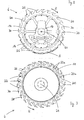
- a mower motor 6 is shown from a bottom view. While in the exemplary embodiment, the rotating blade 14 is arranged on the entire circumference of the Mährotors 6, the fixed counter blade 16 is limited to a portion which covers less than half of the circumferential circle of the Mährotors 6 in the embodiment. Both the rotating blade 14 and the fixed counter blade 16 are each composed of a plurality of sub-segments. Damage to knives makes it easier to replace only the subsegments.
- the Mährotor 6 still has a driver device 18, from the in Fig. 2 the driver teeth 20 are partially visible from the bottom view.
- the enveloping circles of the rotating blade 14 and the fixed counter blade 16 are identical, in the embodiment, the enveloping circle of the tips of the driving teeth 20 is identical to the enveloping circles of the knife.
- the mower rotor 6 rotates in the direction of rotation R about the axis of rotation 24 around.
- Both the rotating blade 14 and the fixed counter blade 16 have a number of cutting edges 26, the cutting edges 26 of the rotating blade 14 having the characteristic that they are arranged on the inwardly facing side of the cutting fingers 30.
- a plurality of cutting edges 26 are formed on the fixed counter blade 14.
- the cutting edges 26 on the fixed counter blade 14 are located on the outwardly facing side of the fixed counter blade 14.
- the distances between the cutting fingers 30 form receiving zones through which stalks to be cut can reach the effective region between the cutting edges 26 of the rotating blade 14 and the fixed counter blade 16.
- Fig. 3 are from the top view of the entrainment device 18 and the receiving pockets 22 better recognizable than from the bottom view.
- the driver device 18 has a number of driver teeth 20, between which the receiving pockets 22 are formed.
- even shorter driver teeth 20a are present on the carrier device 18, by means of which a large receiving pocket 22 formed by longer driver teeth 20 is subdivided into two smaller receiving pockets 22a.
- Fig. 4 is a partial view of the cutting device of a Mährotors 6, which is formed by the rotating blade 14 and the fixed counter blade 16.
- FIG. 4 four cutting phases I to IV are shown.
- the cutting edge 26 of the rotating knife 14 begins to reach a forced cut portion 34 whose length is defined by the length L (G) of the cutting edge 26 of the fixed counter blade 16.
- the cutting edge 26 of the rotating knife 14 has the length L (M).
- the cutting edge 26 of the rotating knife 14 moves to the cutting edge 26 of the fixed Counter knife 16 too.
- the angle between the two cutting edges is still relatively large, and the forced-cut portion 34 is still almost completely open to still let harvest crop stalks that are to cut, and record.
- the cutting edge 26 of the rotating blade 14 begins to overflow the cutting edge of the fixed counter blade 16, the angle of attack between the two cutting edges 26 becomes flatter, and the forced cut portion 34 begins to close.
- the cutting edge 26 of the rotating blade 14 has already passed the major part of the cutting edge 26 of the fixed counter blade 16. The angle of attack between the two cutting edges has become very flat. A stalk which has been located in the forced-cut region 34 should be completely or at least almost cut off in the cut-phase IV. Due to the identical enveloping circles H, nothing can get stuck on the rotating blade 14, since its outer tip always runs over a cutting edge of the fixed counter blade 16 at the end of a cutting phase IV, and adhering crop material is thereby cut.
- FIG. 5 can also be seen from the bottom view that the cutting fingers 30 have on its outwardly facing side an arcuate contour.
- the cutting phases I to IV are designated as they are for Fig. 4 have been explained above. Also in Fig. 5 In the course of the cutting phases I to IV, the interaction of the cutting edges 26 of the rotating blade 14 and the fixed counter blade 16 is clearly visible.
- Fig. 4 is the sliding surface 38 a recognizable, which is formed on the surface of the fixed counter blade 16.
- the sliding surface 38a adjoins the cutting edges 26 of the fixed counter blade 16. Stems coming from the cutting edges 26 are cut, can be taken by the rotating blade 14 and pushed over the sliding surface 38 a.
- the cut stems with the front-side cut surface can also reach the sliding surface 38 b, which is formed on the rotating blade 14. By the sliding surfaces 38 a, 38 b, the cut stems can be taken and fed to the carrier vehicle 4 to.
- Fig. 6 is a partial view of the mower 6 shown from a top view, wherein the driver device 18 with the driver teeth 20 and the receiving pockets 22 can be seen. From the above view, it can be seen that a stem which has been cut by the rotating knife 14 and the fixed counter knife 16 is slidably transported in a receiving pocket 22 on the surfaces of the fixed knife 14 and the fixed counter knife 16 as sliding the driving device 18 rotates in the direction of rotation R.
- the surface of the rotating blade 14 forms the sliding surface 38b and the surface of the fixed counter blade 16 forms the sliding surface 38a.
- Fig. 7 is a Moragotor 6 seen from a front view obliquely.
- the entrainment device 18 consists of two sprockets with driver teeth 20, wherein only the lower sprocket has the additional shorter driver teeth 20a.
- the rotating blade 14 and the fixed blade 16 are clearly visible. Since the rotating blade 14 is directly connected to the entrainment device 18, the rotating blade 14 rotates during a rotational movement of the mower 6 with.
- Fig. 8 a cross-sectional view through a mower 6 is shown.
- the mower 6 has a rotor axis 40 which is placed on the drive shaft 42.
- the fixed blade 16 is fixedly connected to the frame 12, wherein the frame 12 in the embodiment in Fig. 8 shows a transmission housing as a component.
- the rotating blade 14 is fixedly connected to the rotationally movable driving device 18.
- the entrainment device 18 is in turn firmly connected to the rotor axis 40.
- the Mährotor 6 rests with the underside of the rotating blade 40 on the surface of the fixed counter blade 16 and slides in a rotational movement of the Mährotors 6 on the Surface of the fixed counter blade 16. Downwards, the mower 6 is supported in this way by the fixed counter blade 16.
- the Mährotor 6 is rotatably with its rotor axis 40, but mounted longitudinally displaceable on the drive shaft 42 of the Mährotors 6.
- an end stop in the form of a screw 52 is attached on the drive shaft 42.
- the screw 52 which consists of a screw and a washer, limits the path of movement for the rotor axis 40 upwards.
- the washer is pressed by the screw 52 on the surface of a pressure piece 46 having a downwardly facing first support surface 44.
- a second support surface 50 is formed on the pressure piece 46.
- a spring element 48 which consists in the embodiment of a number of disc springs. If the spring element 48 is set by tightening the screw 52 via the pressure member 46 under pressure, the pressure on the rotor shaft 40, whereby the mower 6 with the driver 18 attached thereto and also attached thereto rotating blade 14 on the fixed counter blade 16 transfers is pressed. This results in a contact pressure with which the rotating blade 14 is pressed onto the fixed counter blade 16. Due to the play-free rotational movement of the rotating blade 14 on the fixed counter blade 16, the cutting edges 46 of these two blades can interact like a scissor and produce a smooth cut.
- a coil spring 48 otherwise corresponds to the structure of the Mährotors in Fig. 9 the structure described above in Fig. 8 ,
Landscapes
- Life Sciences & Earth Sciences (AREA)
- Environmental Sciences (AREA)
- Harvester Elements (AREA)
Claims (12)
- Dispositif de fauchage et de cueillage (2) pour couper et évacuer des produits récoltés à tiges, comprenant une pluralité de rotors de fauchage (6) disposés en étant répartis sur la largeur de travail du dispositif de fauchage et de cueillage (2), dans lequel chaque rotor de fauchage (6) présente un dispositif d'entraînement (18) et un dispositif de coupe muni d'une lame tournante (14) et d'une contre-lame fixe (16), et des dents d'entraînement (20) sont disposées sur le dispositif d'entraînement (18) en étant réparties sur la circonférence extérieure de celui-ci, lesdites dents réalisant entre elles des poches de réception (22) pour recevoir et évacuer les produits récoltés coupés, dans lequel les cercles inscrits extérieurs (H) de la lame tournante (14) et de la contre-lame fixe (16) présentent dans au moins une portion de transport dans la zone de coupe du rotor de fauchages (6) une distance identique par rapport à l'axe de rotation (24) du rotor de fauchage (6), caractérisé en ce que la lame tournante (14) est maintenue sur la surface de la contre-lame fixe (16) en étant serrée de manière coulissante dans le rotor de fauchage (6).
- Dispositif de fauchage et de cueillage (2) selon la revendication 1, caractérisé en ce que la lame tournante (14) et la contre-lame fixe (16) réalisent respectivement une pluralité d'arêtes (26), dans lequel les arêtes (26) de la lame tournante (14) sur la face tournée vers l'intérieur sont réalisées par des doigts de coupe (30) de forme longitudinale et disposés en étant espacés les uns des autres sur la circonférence extérieure de la lame tournante (14), et lesdits doigts de coupe (30) sont orientés en avance du sens de rotation (R) de la lame tournante (14), les arêtes (26) de la contre-lame fixe (16) sont disposées sur la face tournée vers l'extérieur de la contre-lame fixe (16), et les arêtes (26) de la contre-lame fixe (16) dépassent vers l'extérieur dans le sens de rotation (R) de la lame tournante (14) de sorte que lors d'une rotation de la lame tournante (14), il en résulte une coupe en ciseaux entre les arêtes (26) de la lame tournante (14) et de la contre-lame fixe (16).
- Dispositif de fauchage et de cueillage (2) selon la revendication 2, caractérisé en ce que les arêtes (26) de la contre-lame fixe (16) réalisent dans la zone dans laquelle elles dépassent vers l'extérieur une zone de coupe forcée (34) et en ce que les zones de coupe forcée (34) consécutives dans le sens de rotation (R) de la lame tournante (14) sont séparées les unes des autres respectivement par une zone de retrait (36) où le bord extérieur (28) de la contre-lame fixe (16) est en retrait vers l'intérieur.
- Dispositif de fauchage et de cueillage (2) selon la revendication 3, caractérisé en ce que le bord extérieur (28) de la contre-lame fixe (16) présente un contour en forme d'arc dans la zone de retrait (36).
- Dispositif de fauchage et de cueillage (2) selon l'une quelconque des revendications précédentes, caractérisé en ce que les doigts de coupe (30) présentent sur leur face tournée vers l'extérieur un contour en forme d'arc.
- Dispositif de fauchage et de cueillage (2) selon l'une quelconque des revendications précédentes 2 à 4, caractérisé en ce que les arêtes (26) de la lame tournante (14) et de la contre-lame fixe (16) présentent un tracé rectiligne au moins sur un tronçon partiel.
- Dispositif de fauchage et de cueillage (2) selon l'une quelconque des revendications précédentes 2 à 4 ou 6, caractérisé en ce que les arêtes (26) de la lame tournante (14) interagissant suivant leur longueur (L) avec une arête opposée (26) de la contre-lame fixe (16) en vue d'une coupe présentent une longueur (L) inférieure à celle des arêtes (26) de la contre-lame fixe (16).
- Dispositif de fauchage et de cueillage (2) selon l'une quelconque des revendications précédentes, caractérisé en ce que la contre-lame fixe (16) présente transversalement au sens de rotation (R) de la lame tournante (14) une surface lisse, réalisée sous forme de surface coulissante (38a) adjacente aux arêtes (26) vers l'intérieur, et la lame tournante (14) présente une surface coulissante (38b) adjacente à l'arête (26) vers l'intérieur, à l'opposé du sens de rotation, surface à partir de laquelle les tiges des produits récoltés coupés peuvent être évacuées du dispositif d'entraînement (18) en position debout, et les surfaces atteignent une profondeur du rotor de fauchage (6) correspondant au moins à une partie de la profondeur des poches de réception (22).
- Dispositif de fauchage et de cueillage (2) selon l'une quelconque des revendications précédentes, caractérisé en ce que les cercles inscrits (H) des rotors de fauchage (6) voisins ne se coupent pas.
- Dispositif de fauchage et de cueillage (2) selon l'une quelconque des revendications précédentes, caractérisé en ce que la vitesse de rotation de la lame tournante (14) est réglable de manière variable.
- Dispositif de fauchage et de cueillage (2) selon l'une quelconque des revendications précédentes, caractérisé en ce que le rotor de fauchage (6) est en appui coulissant par une face inférieure de la lame tournante (14) sur la surface de la contre-lame fixe (16), en ce que le rotor de fauchage (6) est posé par son axe de rotor (40) de manière verrouillée en rotation mais mobile dans le sens longitudinal sur l'arbre de cueillage (42) du rotor de fauchage (6), en ce qu'une butée avec une première surface d'appui (44) réalisée sur celle-ci est reliée à l'arbre d'entrée (42), en ce qu'il existe une deuxième surface d'appui (50) sur l'axe de rotor (40), tournée vers la première surface d'appui (44) et disposée à distance de celle-ci, et en ce qu'un élément faisant ressort (48) est monté entre les première et deuxième surfaces d'appui (42, 50) tournées l'une vers l'autre par lequel sont reliés la butée et l'axe de rotor (40).
- Dispositif de fauchage et de cueillage (2) selon l'une quelconque des revendications précédentes, caractérisé en ce que la butée présente une pièce de pression (46) reliée par vissage à l'arbre d'entrée (42), le vissage formant un taquet pour la pièce de pression (46) par lequel la pièce de pression (46) est maintenue dans une position de blocage.
Applications Claiming Priority (1)
| Application Number | Priority Date | Filing Date | Title |
|---|---|---|---|
| DE102013004858.3A DE102013004858B4 (de) | 2013-03-21 | 2013-03-21 | Mäh- und Einzugseinrichtung zum Schneiden und Abfördern von stängeligem Erntegut |
Publications (2)
| Publication Number | Publication Date |
|---|---|
| EP2781148A1 EP2781148A1 (fr) | 2014-09-24 |
| EP2781148B1 true EP2781148B1 (fr) | 2017-11-22 |
Family
ID=50345846
Family Applications (1)
| Application Number | Title | Priority Date | Filing Date |
|---|---|---|---|
| EP14001021.6A Active EP2781148B1 (fr) | 2013-03-21 | 2014-03-20 | Dispositif de tonte et d'insertion destiné à couper et enlever des produits récoltés en branche |
Country Status (3)
| Country | Link |
|---|---|
| EP (1) | EP2781148B1 (fr) |
| DE (1) | DE102013004858B4 (fr) |
| HU (1) | HUE036420T2 (fr) |
Families Citing this family (2)
| Publication number | Priority date | Publication date | Assignee | Title |
|---|---|---|---|---|
| DE102015206845B4 (de) * | 2015-04-16 | 2024-08-22 | Maschinenfabrik Kemper Gmbh & Co. Kg | Schneidwerk zur Ganzpflanzenernte |
| DE102020119368B4 (de) * | 2020-07-22 | 2024-10-24 | Maschinenfabrik Bernard Krone GmbH & Co. KG | Schneidvorrichtung |
Family Cites Families (6)
| Publication number | Priority date | Publication date | Assignee | Title |
|---|---|---|---|---|
| DE3226876C2 (de) | 1982-07-17 | 1987-04-23 | Maschinenfabrik Kemper Gmbh, 4424 Stadtlohn | Maschine zum Mähen und Häckseln von Mais oder ähnlichem stengelartigen Erntegut |
| HU201202B (en) | 1988-03-28 | 1990-10-28 | Bekescsabai Mezoegazdasagi Gep | Wide-cutting harvesting adapter of rough fodder |
| DE4111981A1 (de) * | 1991-04-12 | 1992-10-15 | Kemper Gmbh Maschf | Maschine zum maehen und haeckseln von mais und dgl. stengelartigem erntegut |
| DE10103595C1 (de) * | 2001-01-26 | 2002-06-20 | Case Harvesting Sys Gmbh | Schneid-und Fördervorrichtung für ein reihenunabhängig arbeitendes Schneidwek |
| DE102007038276B3 (de) * | 2007-08-14 | 2009-03-26 | Maschinenfabrik Kemper Gmbh & Co. Kg | Maschine zur Ernte stängelartiger Pflanzen mit einer Mäh- und Einzugseinrichtung, die ein Schneidmesser und ein das Schneidmesser umschließendes Gegenmesser umfasst |
| DE102010031363A1 (de) * | 2010-07-15 | 2012-01-19 | Maschinenfabrik Kemper Gmbh & Co. Kg | Maschine zur Ernte stängelartiger Pflanzen mit eine elektromotorisch angetriebenen Schneideinrichtung |
-
2013
- 2013-03-21 DE DE102013004858.3A patent/DE102013004858B4/de not_active Expired - Fee Related
-
2014
- 2014-03-20 HU HUE14001021A patent/HUE036420T2/hu unknown
- 2014-03-20 EP EP14001021.6A patent/EP2781148B1/fr active Active
Non-Patent Citations (1)
| Title |
|---|
| None * |
Also Published As
| Publication number | Publication date |
|---|---|
| EP2781148A1 (fr) | 2014-09-24 |
| DE102013004858A1 (de) | 2014-09-25 |
| DE102013004858B4 (de) | 2019-02-21 |
| HUE036420T2 (hu) | 2018-07-30 |
Similar Documents
| Publication | Publication Date | Title |
|---|---|---|
| DE1782740C2 (de) | Mähmaschine mit einem in Arbeitslage dicht über den Boden geführten, langgestreckten, flachen, kastenförmigen Tragkörper | |
| DE102007051989B4 (de) | Rebenvorschneider | |
| DE2848451A1 (de) | Reihenschneid-anbaugeraet | |
| DE3240954A1 (de) | Zuckerrohrerntemaschine | |
| EP3829289B1 (fr) | Appareil adaptable pour récolter des cultures céréalières de type tige | |
| WO2017041888A1 (fr) | Dispositif de récolte de produits à tige sur pied | |
| DE102013004859B4 (de) | Mäh- und Einzugseinrichtung zum Schneiden und Abfördern von stängeligem Erntegut | |
| EP3354126B1 (fr) | Couteau et tambour de hachoir pour une ramasseuse-hacheuse | |
| EP2266384B1 (fr) | Dispositif de sarclage pour plantes aquatiques et bateau de sarclage doté d'un tel dispositif | |
| DE2303528C3 (de) | Maishäcksler | |
| EP2781148B1 (fr) | Dispositif de tonte et d'insertion destiné à couper et enlever des produits récoltés en branche | |
| DE202015005648U1 (de) | Mäh- und Fördergerät zum Ernten von stängeligem Erntegut | |
| WO2014198599A1 (fr) | Moissonneuse pour moissonner des plantes a tiges | |
| DE102005059953A1 (de) | Feldhäcksler | |
| DE60100061T2 (de) | Mulchmäher | |
| EP3130214B1 (fr) | Faucheuse destinée à transporter et à cueillir des produits de récolte à tiges | |
| EP4151071B1 (fr) | Entraînement de lame commutable pour appareil agricole adaptable | |
| WO1987004895A2 (fr) | Ramasseuse-hacheuse | |
| DE9105932U1 (de) | Schneidwalzenpaar für Maispflücker | |
| DE102013007303B4 (de) | Schneidwerk für eine Erntemaschine | |
| WO2019092275A1 (fr) | Accessoire muni de rotors de récolte | |
| DE3123244C2 (fr) | ||
| DE10117154A1 (de) | Häckseleinrichtung | |
| AT501029B1 (de) | Heckenschneidkopf zum schneiden eines bewuchses in einer vorgegebenen höhe oberhalb einer grundfläche | |
| EP3697196A1 (fr) | Élément de coupe doté d'une coupe tractée |
Legal Events
| Date | Code | Title | Description |
|---|---|---|---|
| PUAI | Public reference made under article 153(3) epc to a published international application that has entered the european phase |
Free format text: ORIGINAL CODE: 0009012 |
|
| 17P | Request for examination filed |
Effective date: 20140320 |
|
| AK | Designated contracting states |
Kind code of ref document: A1 Designated state(s): AL AT BE BG CH CY CZ DE DK EE ES FI FR GB GR HR HU IE IS IT LI LT LU LV MC MK MT NL NO PL PT RO RS SE SI SK SM TR |
|
| AX | Request for extension of the european patent |
Extension state: BA ME |
|
| R17P | Request for examination filed (corrected) |
Effective date: 20150217 |
|
| RBV | Designated contracting states (corrected) |
Designated state(s): AL AT BE BG CH CY CZ DE DK EE ES FI FR GB GR HR HU IE IS IT LI LT LU LV MC MK MT NL NO PL PT RO RS SE SI SK SM TR |
|
| GRAP | Despatch of communication of intention to grant a patent |
Free format text: ORIGINAL CODE: EPIDOSNIGR1 |
|
| GRAS | Grant fee paid |
Free format text: ORIGINAL CODE: EPIDOSNIGR3 |
|
| INTG | Intention to grant announced |
Effective date: 20170616 |
|
| GRAA | (expected) grant |
Free format text: ORIGINAL CODE: 0009210 |
|
| AK | Designated contracting states |
Kind code of ref document: B1 Designated state(s): AL AT BE BG CH CY CZ DE DK EE ES FI FR GB GR HR HU IE IS IT LI LT LU LV MC MK MT NL NO PL PT RO RS SE SI SK SM TR |
|
| REG | Reference to a national code |
Ref country code: GB Ref legal event code: FG4D Free format text: NOT ENGLISH |
|
| REG | Reference to a national code |
Ref country code: CH Ref legal event code: EP |
|
| REG | Reference to a national code |
Ref country code: IE Ref legal event code: FG4D Free format text: LANGUAGE OF EP DOCUMENT: GERMAN |
|
| REG | Reference to a national code |
Ref country code: AT Ref legal event code: REF Ref document number: 947501 Country of ref document: AT Kind code of ref document: T Effective date: 20171215 |
|
| REG | Reference to a national code |
Ref country code: DE Ref legal event code: R096 Ref document number: 502014006286 Country of ref document: DE |
|
| REG | Reference to a national code |
Ref country code: NL Ref legal event code: MP Effective date: 20171122 |
|
| REG | Reference to a national code |
Ref country code: LT Ref legal event code: MG4D |
|
| PG25 | Lapsed in a contracting state [announced via postgrant information from national office to epo] |
Ref country code: ES Free format text: LAPSE BECAUSE OF FAILURE TO SUBMIT A TRANSLATION OF THE DESCRIPTION OR TO PAY THE FEE WITHIN THE PRESCRIBED TIME-LIMIT Effective date: 20171122 Ref country code: NO Free format text: LAPSE BECAUSE OF FAILURE TO SUBMIT A TRANSLATION OF THE DESCRIPTION OR TO PAY THE FEE WITHIN THE PRESCRIBED TIME-LIMIT Effective date: 20180222 Ref country code: SE Free format text: LAPSE BECAUSE OF FAILURE TO SUBMIT A TRANSLATION OF THE DESCRIPTION OR TO PAY THE FEE WITHIN THE PRESCRIBED TIME-LIMIT Effective date: 20171122 Ref country code: FI Free format text: LAPSE BECAUSE OF FAILURE TO SUBMIT A TRANSLATION OF THE DESCRIPTION OR TO PAY THE FEE WITHIN THE PRESCRIBED TIME-LIMIT Effective date: 20171122 Ref country code: NL Free format text: LAPSE BECAUSE OF FAILURE TO SUBMIT A TRANSLATION OF THE DESCRIPTION OR TO PAY THE FEE WITHIN THE PRESCRIBED TIME-LIMIT Effective date: 20171122 Ref country code: LT Free format text: LAPSE BECAUSE OF FAILURE TO SUBMIT A TRANSLATION OF THE DESCRIPTION OR TO PAY THE FEE WITHIN THE PRESCRIBED TIME-LIMIT Effective date: 20171122 |
|
| PG25 | Lapsed in a contracting state [announced via postgrant information from national office to epo] |
Ref country code: GR Free format text: LAPSE BECAUSE OF FAILURE TO SUBMIT A TRANSLATION OF THE DESCRIPTION OR TO PAY THE FEE WITHIN THE PRESCRIBED TIME-LIMIT Effective date: 20180223 Ref country code: HR Free format text: LAPSE BECAUSE OF FAILURE TO SUBMIT A TRANSLATION OF THE DESCRIPTION OR TO PAY THE FEE WITHIN THE PRESCRIBED TIME-LIMIT Effective date: 20171122 Ref country code: LV Free format text: LAPSE BECAUSE OF FAILURE TO SUBMIT A TRANSLATION OF THE DESCRIPTION OR TO PAY THE FEE WITHIN THE PRESCRIBED TIME-LIMIT Effective date: 20171122 Ref country code: BG Free format text: LAPSE BECAUSE OF FAILURE TO SUBMIT A TRANSLATION OF THE DESCRIPTION OR TO PAY THE FEE WITHIN THE PRESCRIBED TIME-LIMIT Effective date: 20180222 Ref country code: RS Free format text: LAPSE BECAUSE OF FAILURE TO SUBMIT A TRANSLATION OF THE DESCRIPTION OR TO PAY THE FEE WITHIN THE PRESCRIBED TIME-LIMIT Effective date: 20171122 |
|
| REG | Reference to a national code |
Ref country code: HU Ref legal event code: AG4A Ref document number: E036420 Country of ref document: HU |
|
| PG25 | Lapsed in a contracting state [announced via postgrant information from national office to epo] |
Ref country code: EE Free format text: LAPSE BECAUSE OF FAILURE TO SUBMIT A TRANSLATION OF THE DESCRIPTION OR TO PAY THE FEE WITHIN THE PRESCRIBED TIME-LIMIT Effective date: 20171122 Ref country code: CY Free format text: LAPSE BECAUSE OF FAILURE TO SUBMIT A TRANSLATION OF THE DESCRIPTION OR TO PAY THE FEE WITHIN THE PRESCRIBED TIME-LIMIT Effective date: 20171122 Ref country code: CZ Free format text: LAPSE BECAUSE OF FAILURE TO SUBMIT A TRANSLATION OF THE DESCRIPTION OR TO PAY THE FEE WITHIN THE PRESCRIBED TIME-LIMIT Effective date: 20171122 Ref country code: SK Free format text: LAPSE BECAUSE OF FAILURE TO SUBMIT A TRANSLATION OF THE DESCRIPTION OR TO PAY THE FEE WITHIN THE PRESCRIBED TIME-LIMIT Effective date: 20171122 Ref country code: DK Free format text: LAPSE BECAUSE OF FAILURE TO SUBMIT A TRANSLATION OF THE DESCRIPTION OR TO PAY THE FEE WITHIN THE PRESCRIBED TIME-LIMIT Effective date: 20171122 |
|
| REG | Reference to a national code |
Ref country code: DE Ref legal event code: R097 Ref document number: 502014006286 Country of ref document: DE |
|
| PG25 | Lapsed in a contracting state [announced via postgrant information from national office to epo] |
Ref country code: PL Free format text: LAPSE BECAUSE OF FAILURE TO SUBMIT A TRANSLATION OF THE DESCRIPTION OR TO PAY THE FEE WITHIN THE PRESCRIBED TIME-LIMIT Effective date: 20171122 Ref country code: SM Free format text: LAPSE BECAUSE OF FAILURE TO SUBMIT A TRANSLATION OF THE DESCRIPTION OR TO PAY THE FEE WITHIN THE PRESCRIBED TIME-LIMIT Effective date: 20171122 Ref country code: RO Free format text: LAPSE BECAUSE OF FAILURE TO SUBMIT A TRANSLATION OF THE DESCRIPTION OR TO PAY THE FEE WITHIN THE PRESCRIBED TIME-LIMIT Effective date: 20171122 Ref country code: IT Free format text: LAPSE BECAUSE OF FAILURE TO SUBMIT A TRANSLATION OF THE DESCRIPTION OR TO PAY THE FEE WITHIN THE PRESCRIBED TIME-LIMIT Effective date: 20171122 |
|
| PG25 | Lapsed in a contracting state [announced via postgrant information from national office to epo] |
Ref country code: MT Free format text: LAPSE BECAUSE OF FAILURE TO SUBMIT A TRANSLATION OF THE DESCRIPTION OR TO PAY THE FEE WITHIN THE PRESCRIBED TIME-LIMIT Effective date: 20171122 |
|
| PLBE | No opposition filed within time limit |
Free format text: ORIGINAL CODE: 0009261 |
|
| STAA | Information on the status of an ep patent application or granted ep patent |
Free format text: STATUS: NO OPPOSITION FILED WITHIN TIME LIMIT |
|
| 26N | No opposition filed |
Effective date: 20180823 |
|
| REG | Reference to a national code |
Ref country code: CH Ref legal event code: PL |
|
| GBPC | Gb: european patent ceased through non-payment of renewal fee |
Effective date: 20180320 |
|
| PG25 | Lapsed in a contracting state [announced via postgrant information from national office to epo] |
Ref country code: SI Free format text: LAPSE BECAUSE OF FAILURE TO SUBMIT A TRANSLATION OF THE DESCRIPTION OR TO PAY THE FEE WITHIN THE PRESCRIBED TIME-LIMIT Effective date: 20171122 Ref country code: MC Free format text: LAPSE BECAUSE OF FAILURE TO SUBMIT A TRANSLATION OF THE DESCRIPTION OR TO PAY THE FEE WITHIN THE PRESCRIBED TIME-LIMIT Effective date: 20171122 |
|
| REG | Reference to a national code |
Ref country code: IE Ref legal event code: MM4A |
|
| PG25 | Lapsed in a contracting state [announced via postgrant information from national office to epo] |
Ref country code: LU Free format text: LAPSE BECAUSE OF NON-PAYMENT OF DUE FEES Effective date: 20180320 |
|
| PG25 | Lapsed in a contracting state [announced via postgrant information from national office to epo] |
Ref country code: IE Free format text: LAPSE BECAUSE OF NON-PAYMENT OF DUE FEES Effective date: 20180320 |
|
| PG25 | Lapsed in a contracting state [announced via postgrant information from national office to epo] |
Ref country code: GB Free format text: LAPSE BECAUSE OF NON-PAYMENT OF DUE FEES Effective date: 20180320 Ref country code: CH Free format text: LAPSE BECAUSE OF NON-PAYMENT OF DUE FEES Effective date: 20180331 Ref country code: LI Free format text: LAPSE BECAUSE OF NON-PAYMENT OF DUE FEES Effective date: 20180331 |
|
| PG25 | Lapsed in a contracting state [announced via postgrant information from national office to epo] |
Ref country code: FR Free format text: LAPSE BECAUSE OF NON-PAYMENT OF DUE FEES Effective date: 20180331 |
|
| PG25 | Lapsed in a contracting state [announced via postgrant information from national office to epo] |
Ref country code: TR Free format text: LAPSE BECAUSE OF FAILURE TO SUBMIT A TRANSLATION OF THE DESCRIPTION OR TO PAY THE FEE WITHIN THE PRESCRIBED TIME-LIMIT Effective date: 20171122 |
|
| PG25 | Lapsed in a contracting state [announced via postgrant information from national office to epo] |
Ref country code: PT Free format text: LAPSE BECAUSE OF FAILURE TO SUBMIT A TRANSLATION OF THE DESCRIPTION OR TO PAY THE FEE WITHIN THE PRESCRIBED TIME-LIMIT Effective date: 20171122 |
|
| PG25 | Lapsed in a contracting state [announced via postgrant information from national office to epo] |
Ref country code: MK Free format text: LAPSE BECAUSE OF NON-PAYMENT OF DUE FEES Effective date: 20171122 |
|
| PG25 | Lapsed in a contracting state [announced via postgrant information from national office to epo] |
Ref country code: AL Free format text: LAPSE BECAUSE OF FAILURE TO SUBMIT A TRANSLATION OF THE DESCRIPTION OR TO PAY THE FEE WITHIN THE PRESCRIBED TIME-LIMIT Effective date: 20171122 Ref country code: IS Free format text: LAPSE BECAUSE OF FAILURE TO SUBMIT A TRANSLATION OF THE DESCRIPTION OR TO PAY THE FEE WITHIN THE PRESCRIBED TIME-LIMIT Effective date: 20180322 |
|
| REG | Reference to a national code |
Ref country code: AT Ref legal event code: MM01 Ref document number: 947501 Country of ref document: AT Kind code of ref document: T Effective date: 20190320 |
|
| PG25 | Lapsed in a contracting state [announced via postgrant information from national office to epo] |
Ref country code: AT Free format text: LAPSE BECAUSE OF NON-PAYMENT OF DUE FEES Effective date: 20190320 |
|
| PGFP | Annual fee paid to national office [announced via postgrant information from national office to epo] |
Ref country code: DE Payment date: 20260320 Year of fee payment: 13 |
|
| PGFP | Annual fee paid to national office [announced via postgrant information from national office to epo] |
Ref country code: BE Payment date: 20260323 Year of fee payment: 13 |
|
| PGFP | Annual fee paid to national office [announced via postgrant information from national office to epo] |
Ref country code: HU Payment date: 20260313 Year of fee payment: 13 |