EP2781273A1 - Walzvorrichtung und verfahren dafür - Google Patents
Walzvorrichtung und verfahren dafür Download PDFInfo
- Publication number
- EP2781273A1 EP2781273A1 EP12848821.0A EP12848821A EP2781273A1 EP 2781273 A1 EP2781273 A1 EP 2781273A1 EP 12848821 A EP12848821 A EP 12848821A EP 2781273 A1 EP2781273 A1 EP 2781273A1
- Authority
- EP
- European Patent Office
- Prior art keywords
- forming roll
- roll
- rolling
- sheet metal
- forming
- Prior art date
- Legal status (The legal status is an assumption and is not a legal conclusion. Google has not performed a legal analysis and makes no representation as to the accuracy of the status listed.)
- Withdrawn
Links
- 238000005096 rolling process Methods 0.000 title claims abstract description 158
- 238000000034 method Methods 0.000 title claims abstract description 49
- 230000007246 mechanism Effects 0.000 claims abstract description 182
- 239000002184 metal Substances 0.000 claims abstract description 107
- 229910052751 metal Inorganic materials 0.000 claims abstract description 107
- 230000008569 process Effects 0.000 claims description 31
- 238000005452 bending Methods 0.000 claims description 11
- 238000007667 floating Methods 0.000 claims description 4
- 238000004519 manufacturing process Methods 0.000 description 7
- 230000009471 action Effects 0.000 description 6
- 239000000463 material Substances 0.000 description 5
- 238000009826 distribution Methods 0.000 description 4
- 238000009828 non-uniform distribution Methods 0.000 description 4
- 230000006835 compression Effects 0.000 description 3
- 238000007906 compression Methods 0.000 description 3
- 239000000314 lubricant Substances 0.000 description 3
- 238000012545 processing Methods 0.000 description 3
- RYGMFSIKBFXOCR-UHFFFAOYSA-N Copper Chemical compound [Cu] RYGMFSIKBFXOCR-UHFFFAOYSA-N 0.000 description 2
- 229910052802 copper Inorganic materials 0.000 description 2
- 239000010949 copper Substances 0.000 description 2
- 230000005484 gravity Effects 0.000 description 2
- 238000012986 modification Methods 0.000 description 2
- 230000004048 modification Effects 0.000 description 2
- 230000009467 reduction Effects 0.000 description 2
- 210000000746 body region Anatomy 0.000 description 1
- 230000008859 change Effects 0.000 description 1
- 238000011161 development Methods 0.000 description 1
- 239000010408 film Substances 0.000 description 1
- 238000011089 mechanical engineering Methods 0.000 description 1
- 238000003672 processing method Methods 0.000 description 1
- 230000002035 prolonged effect Effects 0.000 description 1
- 238000007493 shaping process Methods 0.000 description 1
- 239000010409 thin film Substances 0.000 description 1
Images



Classifications
-
- B—PERFORMING OPERATIONS; TRANSPORTING
- B21—MECHANICAL METAL-WORKING WITHOUT ESSENTIALLY REMOVING MATERIAL; PUNCHING METAL
- B21B—ROLLING OF METAL
- B21B27/00—Rolls, roll alloys or roll fabrication; Lubricating, cooling or heating rolls while in use
- B21B27/02—Shape or construction of rolls
-
- B—PERFORMING OPERATIONS; TRANSPORTING
- B21—MECHANICAL METAL-WORKING WITHOUT ESSENTIALLY REMOVING MATERIAL; PUNCHING METAL
- B21B—ROLLING OF METAL
- B21B13/00—Metal-rolling stands, i.e. an assembly composed of a stand frame, rolls, and accessories
- B21B13/14—Metal-rolling stands, i.e. an assembly composed of a stand frame, rolls, and accessories having counter-pressure devices acting on rolls to inhibit deflection of same under load; Back-up rolls
-
- B—PERFORMING OPERATIONS; TRANSPORTING
- B21—MECHANICAL METAL-WORKING WITHOUT ESSENTIALLY REMOVING MATERIAL; PUNCHING METAL
- B21B—ROLLING OF METAL
- B21B1/00—Metal-rolling methods or mills for making semi-finished products of solid or profiled cross-section; Sequence of operations in milling trains; Layout of rolling-mill plant, e.g. grouping of stands; Succession of passes or of sectional pass alternations
- B21B1/22—Metal-rolling methods or mills for making semi-finished products of solid or profiled cross-section; Sequence of operations in milling trains; Layout of rolling-mill plant, e.g. grouping of stands; Succession of passes or of sectional pass alternations for rolling plates, strips, bands or sheets of indefinite length
-
- B—PERFORMING OPERATIONS; TRANSPORTING
- B21—MECHANICAL METAL-WORKING WITHOUT ESSENTIALLY REMOVING MATERIAL; PUNCHING METAL
- B21B—ROLLING OF METAL
- B21B29/00—Counter-pressure devices acting on rolls to inhibit deflection of same under load, e.g. backing rolls ; Roll bending devices, e.g. hydraulic actuators acting on roll shaft ends
-
- B—PERFORMING OPERATIONS; TRANSPORTING
- B21—MECHANICAL METAL-WORKING WITHOUT ESSENTIALLY REMOVING MATERIAL; PUNCHING METAL
- B21B—ROLLING OF METAL
- B21B31/00—Rolling stand structures; Mounting, adjusting, or interchanging rolls, roll mountings, or stand frames
- B21B31/16—Adjusting or positioning rolls
-
- B—PERFORMING OPERATIONS; TRANSPORTING
- B21—MECHANICAL METAL-WORKING WITHOUT ESSENTIALLY REMOVING MATERIAL; PUNCHING METAL
- B21B—ROLLING OF METAL
- B21B99/00—Subject matter not provided for in other groups of this subclass
-
- B—PERFORMING OPERATIONS; TRANSPORTING
- B21—MECHANICAL METAL-WORKING WITHOUT ESSENTIALLY REMOVING MATERIAL; PUNCHING METAL
- B21D—WORKING OR PROCESSING OF SHEET METAL OR METAL TUBES, RODS OR PROFILES WITHOUT ESSENTIALLY REMOVING MATERIAL; PUNCHING METAL
- B21D5/00—Bending sheet metal along straight lines, e.g. to form simple curves
- B21D5/06—Bending sheet metal along straight lines, e.g. to form simple curves by drawing procedure making use of dies or forming-rollers, e.g. making profiles
- B21D5/08—Bending sheet metal along straight lines, e.g. to form simple curves by drawing procedure making use of dies or forming-rollers, e.g. making profiles making use of forming-rollers
Definitions
- the present invention relates to a rolling device, in particular to a rolling device for three-dimensional curved surface forming or thin sheet (plate) rolling of a sheet metal (sheet), which belongs to a field of mechanical engineering.
- the present invention also relates to a method for curved surface forming and thin sheet metal rolling corresponding thereto.
- three-dimensional curved surface forming of a sheet is mainly achieved by adopting a forming method using a die, which involves a high cost and a long cycle of die manufacturing and adjusting, and a large die and a large press are needed if a large-size three-dimensional curved surface is to be formed by using a die.
- a traditional plate bending device can be used to form a cylindrical, conical or other simple curved surface, but it has difficulty in forming a real three-dimensional curved surface.
- a three-dimensional flexible bending processing method can be used to form a three-dimensional curved surface, but it adopts discrete working rolls, resulting in a low surface quality of a formed part, and thus the application and development thereof are restricted. Furthermore, generally sheet rolling is mostly achieved by adopting a large-diameter two-roll or multi-roll mill. For thin sheet rolling, since the elastic flattening of a roll is directly proportional to the diameter of the roll, the elastic flattening value of the roll per se is often larger than the rolling reduction of the sheet metal to be rolled if a large-diameter two-roll mill is adopted to roll the thin sheet. Therefore, when the material of a roll is selected, the roll diameter must be reduced if the elastic flattening value of the roll is to be reduced.
- the diameter of the roll also needs to be reduced if the rolling force is to be reduced.
- a problem of insufficient rigidity of the roll may occur accordingly, and at the same time a roll neck that transfers the rolling torque also becomes smaller; therefore, a plurality of backup rolls are needed to support a small-diameter working roll in multiple directions respectively, and the small-diameter working roll is driven by the backup rolls.
- Such a multi-roll mill can meet a requirement of a small diameter and a high rigidity of the working roll, but it increases the structural complexity and the manufacturing cost thereof.
- the object of the present invention is to provide a rolling device capable of achieving three-dimensional curved surface forming or thin sheet rolling of a sheet metal simply, quickly and at a low cost, and provide a method corresponding thereto.
- the present invention provides a rolling device for three-dimensional curved surface forming or thin sheet rolling of a sheet metal, comprising a forming roll, a supporting mechanism, an adjusting mechanism and a driving mechanism, characterized in that the forming roll comprises an upper forming roll and a lower forming roll, which have small diameters and are easy to be bending deformed; the supporting mechanism is a multi-point supporting mechanism or an overall supporting mechanism for supporting the forming roll; the adjusting mechanism is a multi-point shape adjusting mechanism and/or an overall displacing mechanism, capable of adjusting the shape and/or relative height of the forming roll; and the driving mechanism is capable of applying a torque to one or two ends of the upper forming roll and/or the lower forming roll, so that the upper forming roll and/or the lower forming roll are/is caused to rotate, and whereby a sheet metal is passed through a roll gap between the upper forming roll and the lower forming roll and is roll formed.
- the upper forming roll and/or the lower forming roll can be caused to have a certain deflection, and the roll gap between the upper forming roll and the lower forming roll can be distributed non-uniformly, so that the sheet metal has different compression ratios at different regions in the same cross section in the width direction, and whereby the sheet metal has a non-uniform, longitudinal extension at different points in the width direction, and finally the sheet metal is deformed non-uniformly in a rolling process to achieve three-dimensional curved surface forming.
- the device is suitable for forming a long-size three-dimensional curved surface part.
- the adjusting mechanism adjusts the shape(s) of the upper forming roll and/or the lower forming roll or the relative height of the forming roll, so that the roll gap between the upper and lower forming rolls is distributed non-uniformly, thin sheet or ultra-thin sheet rolling or variable section rolling can be achieved.
- a consecutive forming or shaping of a large sheet metal can be achieved by a small-sized equipment.
- the device As compared with a traditional die forming device, the device has the following advantages: the procedures for designing, manufacturing and tryout a die can be eliminated, the production cycle can be shortened, the working efficiency can be improved, and the processing cost can be reduced; and as compared with the way of manual forming, the surface quality of the formed part can be improved, and materials, manpower and processing time can be saved. Therefore, the rolling device according to the present invention can achieve three-dimensional curved surface forming or thin sheet rolling of a sheet metal simply, quickly and at a low cost.
- the forming roll is a rotating body having a generatrix of a straight or curved line, and the number of each of the upper forming roll and the lower forming roll is one or more.
- the non-uniformity of the roll gap can be achieved by the change of the generatry of the forming roll, so that the forming roll can be rotated without a deflection or with a small deflection, thereby a fatigue load on the forming roll can be reduced and the service life of the forming roll can be increased.
- single-pass rolling can be achieved; and when there are a plurality of upper forming rolls and a plurality of lower forming rolls, consecutive multi-pass rolling can be achieved.
- the upper forming roll and/or the lower forming roll can be composed of two roll segments, which are capable of being rotated in opposite directions with different speeds, in opposite directions with the same speed, in the same direction with different speeds or in the same direction with the same speed.
- the adjusting mechanism can adjust the shapes of the two roll segments respectively, and the driving mechanism can apply torques to the two roll segments respectively, so that acting forces and friction forces with different values and in opposite directions, with the same value and in opposite directions, with different values and in the same direction, or with the same value and in the same direction can be applied on two sides of the sheet metal respectively, and thereby two sides of the sheet metal are rotated with different speeds or the same speed, or are fed with different speeds or the same speed, so as to achieve rotary forming or curved feeding and forming.
- a centering mechanism can be arranged between the two roll segments, and the centering mechanism is used to fix a point on the sheet metal, so that the sheet metal is incapable of being moved as a whole, but only capable of being rotated about the point.
- the centering mechanism mainly consists of a clamping mechanism and a rotating mechanism.
- a point of the sheet metal can be fixed under the action of the clamping mechanism and the rotating mechanism, so that the sheet metal can be caused to rotate about the fixed point, and thus an overall movement of the sheet metal during rotation is avoided.
- the adjusting mechanism changes the deflection or the relative height of the forming roll according to need before the sheet metal is passed through the roll gap and is roll formed; or it changes the deflection or the relative height of the forming roll in real time according to need during a process in which the sheet metal is passed through the roll gap and is rolled.
- the deflection of the forming roll can be adjusted to a degree as required by the multi-point shape adjusting mechanism before a rolling process, so that the roll gap between the upper forming roll and the lower forming roll is distributed non-uniformly, then different compression ratios are generated at different regions in the same cross section of the width direction of the sheet metal, and whereby the sheet metal is longitudinally extended non-uniformly at different points in the width direction, and finally the sheet metal is deformed in the rolling process to achieve three-dimensional curved surface forming.
- Different curved surfaces can be formed by controlling the distribution or profile of the values of the roll gap: if a value of the roll gap in a central region of the forming roll is smaller than the values of the roll gap in two side regions, and the roll gap changes gradually, then a spherical curved surface or a spherical-like curved surface can be formed; if the value of the roll gap in the central region of the forming roll is larger than those in the two side regions, and the roll gap changes gradually, then a saddle-shaped curved surface or a saddle-like curved surface can be formed; if the value of the roll gap in the central region of the forming roll is larger than those in the two side regions, the roll gap changes gradually, and the sheet metal is fed along a diagonal direction, or a value of the roll gap on one side of the forming roll is larger than that on the other side of the forming roll, the roll gap between the forming rolls changes gradually, and a value of the roll gap at the side where it is originally large becomes smaller gradually and the roll gap
- the overall supporting mechanism is a flexible supporting mechanism for providing a full-length support for the forming roll, and the flexible supporting mechanism has a sectional dimension larger than that of the forming roll, but is capable of being flexurally deformed; and the adjusting mechanism is a multi-point shape adjusting mechanism for performing a multi-point shape adjustment to the forming roll through the flexible supporting mechanism, or it further comprises an overall displacing mechanism for adjusting the relative height of the forming roll.
- the supporting mechanism has a rigidity larger than that of the forming roll, but can be caused to a bending deformation under the action of the multi-point shape adjusting mechanism, so that the shape of the forming roll after a shape adjustment changes more uniformly, and at the same time the number of shape adjustment points can also be reduced, the rigidity of the forming roll is increased, and thus the forming quality is improved.
- the adjusting mechanism may further comprise an overall displacing mechanism for adjusting the relative height of the forming roll; and the adjustment may be performed before a forming process, and may also be performed in real time during the forming process, so as to form different curved surfaces.
- the overall supporting mechanism is a rigid supporting mechanism for providing a full-length support for the forming roll, and the rigid supporting mechanism has a sectional dimension much larger than that of the forming roll, the rigid supporting mechanism does not undergo a deformation or only undergoes a deformation in a very small degree during a rolling process; and the adjusting mechanism is an overall displacing mechanism for adjusting the relative height of the forming roll.
- the overall supporting mechanism has a property of high-rigidity, and does not undergo a deformation or only undergoes a deformation in a very small degree during a forming process, so that it can be used to replace supporting rolls in a multi-roll rolling device, and then the rigidity of the forming roll can be ensured while the structure of the device is simplified, and a bending deformation of the forming roll during the rolling process can be prevented.
- the overall displacing mechanism can adjust the relative height of the forming roll; and the adjustment may be performed before the forming process, and may also be performed in real time during the forming process, so as to achieve different types of rolling.
- the overall supporting mechanism is kept in surface contact with and sliding fit to the forming roll, and an oil groove is formed on a contact surface between the overall supporting mechanism and the forming roll, and additionally, one or more oil passages opening from the outside to the contact surface are formed in the overall supporting mechanism.
- one or more oil grooves and oil passages are arranged inside the overall supporting mechanism, a lubricant can consecutively enter the contact surface between the overall supporting mechanism and the forming roll by a principle of a sliding bearing or a dynamic pressure bearing, and an oil film is generated on the contact surface to separate the overall supporting mechanism from the forming roll, thereby the friction between the overall supporting mechanism and the forming roll is reduced.
- the driving mechanism comprises at least one driving roll, and the forming roll is driven by the driving roll, the driving roll is located between the supporting mechanism and the forming roll, the supporting mechanism is kept in surface contact with and sliding fit to the driving roll, and the driving roll is kept in line contact with and rolling fit to the forming roll.
- the driving roll can apply a torque to a supported region of the forming roll, so as to reduce the moment of force generated by the forming roll due to the action between the forming roll and the sheet metal, increase the overall rotational torque of the forming roll, and avoid a rotational hysteresis phenomenon in the central region of the forming roll due to the action between the forming roll and the sheet metal, thereby the service life of the forming roll is prolonged, and at the same time the forming precision of the formed part is improved.
- the rolling device further comprises one flexible holding mechanisms for holding the sheet metal before and/or after a forming process, arranged in front of the forming roll and/or behind the forming roll along a traveling direction of the sheet metal.
- the sheet metal before and/or after a forming process can be held by the flexible holding mechanism, so as to suppress additional deformations of the sheet metal due to gravity or the like when the sheet metal is fed and/or discharged, and improve the forming quality.
- the flexible holding mechanism comprises any one of a soft-shaft-based holding mechanism, a plurality of floating holding units and a multi-point holding mechanism with a function of height adjustment.
- the flexible holding mechanism can hold the sheet metal before and/or after a forming process, and the flexible holding mechanism can adjust a holding height according to the shape of the sheet metal, so as to adapt to the shape of the sheet metal, and inhibit additional deformations of the sheet metal due to gravity or the like when the sheet metal is fed and/or discharged.
- the present invention provides a rolling device for three-dimensional curved surface forming or thin sheet rolling of a sheet metal, capable of achieving three-dimensional curved surface forming or thin sheet rolling of a sheet metal simply, quickly and at a low cost.
- the present invention also provides a rolling method for three-dimensional curved surface forming or thin sheet rolling of a sheet metal by using the above rolling device, comprising an adjusting step and a rolling step, wherein in the adjusting step, the adjusting mechanism adjusts the shape(s) or the relative height(s) of the upper forming roll and/or the lower forming roll, so that the roll gap formed between the upper forming roll and the lower forming roll is non-uniformly distributed or uniformly distributed; and in the rolling step, a sheet metal is passed through the roll gap, and the sheet metal is rolled by the upper forming roll and/or the lower forming roll.
- the adjusting step can be executed before the rolling step, or the adjusting step and the rolling step are executed simultaneously. According to the method, three-dimensional curved surface forming or thin sheet rolling of a sheet metal can be achieved simply, quickly and at a low cost.
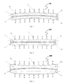
- Fig. 1 is a schematic view of a rolling device 100 related to one embodiment of the present invention, and is a sectional schematic view taken in a direction perpendicular to a direction along which a sheet metal is passed through during a rolling process in which the sheet metal is passed through a roll gap and is rolled.
- the rolling device 100 comprises a forming roll 1 (generally also be termed as working roll in the art) for rolling a sheet metal 4, a multi-point supporting mechanism 2a with a function of supporting the forming roll 1, a multi-point shape adjusting mechanism 3 with a function of adjusting the shape of the forming roll 1, and a driving mechanism (not shown) for rotating the forming roll;
- the forming roll 1 comprises an upper forming roll 1a and a lower forming roll 1b, each of the upper forming roll 1a and the lower forming roll 1b is supported by a plurality of multi-point supporting mechanisms 2a, the multi-point shape adjusting mechanism 3 can cause a bending deformation to the upper forming roll 1a and the lower forming roll 1b respectively, and can cause a roll gap (i.e.
- the driving mechanism cause the upper forming roll 1a and the lower forming roll 1b to rotate so that the sheet metal is passed through the roll gap and is roll formed.
- the upper forming roll 1a and the lower forming roll 1b are cylindrical rolls with relatively small diameters respectively, so that the rolls are easy to be bending deformed due to the small diameters thereof, and under the action of the multi-point shape adjusting mechanism 3, the upper forming roll 1a and the lower forming roll 1b can be bent in different degrees respectively, so that a roll gap between the upper forming roll 1a and the lower forming roll 1b is distributed non-uniformly, and the roll gap in a central region is smaller than those in two side regions, the driving mechanism applies a torque at one or two ends of the forming roll 1, so that different compression ratios are generated at different regions in the same cross section of the width direction of the sheet metal 4, and whereby the sheet metal 4 is extended non-uniformly at different points in the width direction, and finally the sheet metal 4 is deformed in the rolling process to achieve three-dimensional curved surface forming.
- the roll gap of the forming roll 1 in the rolling device 100 is non-uniformly distributed, and different curved surfaces are formed by controlling the non-uniform distribution of the roll gap: if the roll gap in the central region of the forming roll 1 is smaller than those in the two side regions, and the roll gap changes gradually, a spherical curved surface or a spherical-like curved surface can be formed; if the roll gap in the central region of the forming roll 1 is larger than those in the two side regions, and the roll gap changes gradually, a saddle-shaped curved surface or a saddle-like curved surface can be formed; if the roll gap in the central region of the forming roll 1 is larger than those in the two side regions, the roll gap changes gradually, and the sheet metal 4 is fed along a diagonal direction, or the roll gap on one side of the forming roll 1 is larger than that on the other side thereof, the roll gap changes gradually, and
- Fig. 2 is a schematic view of a rolling device 200 related to another embodiment of the present invention, and is a sectional schematic view in a direction perpendicular to a direction along which a sheet metal is passed through during a process in which the sheet metal is passed through a roll gap and is rolled.
- An upper forming roll 1a and a lower forming roll 1b of the rolling device 200 are also cylindrical rolls with relatively small diameters, but only one of the forming rolls 1 is bent under the action of a multi-point shape adjusting mechanism 3, so that a value of the roll gap in a central region of the two forming rolls 1 is smaller than those in two side regions.
- the driving mechanism applies a torque at one or two ends of the forming roll 1, so that different plastic deformations are generated on the sheet metal 4 at different regions during a consecutive rolling process to form a curved surface shape.
- the values of the roll gap in the two side regions of the two forming rolls 1 may be smaller than that of the central region, or for a value of the roll gap of one side region to be smaller than that of the other side region, or for the roll gap to be undulated.
- a thin flat sheet rolling process can be performed by adopting two small-diameter forming rolls 1.
- Fig. 3 is a schematic view of a rolling device 300 related to another embodiment of the present invention, and is a sectional schematic view in a direction perpendicular to a direction along which a sheet metal is passed through during a process in which the sheet metal is passed through a roll gap and is rolled.
- the generatrices of the upper forming roll 1a and the lower forming roll 1b are arc lines, so that the two forming rolls 1 can produce a roll gap distributed non-uniformly between them without being bent, and a value of the roll gap of a central region is smaller than those of two side regions.
- a multi-point supporting mechanism 2a supports the forming roll 1, and a multi-point shape adjusting mechanism 3 can cause a bending deformation to the forming roll 1.
- the value of the roll gap of the central region may be larger than those of the two side regions of the two forming rolls 1, or for a value of the roll gap of one side region to be smaller than that of the other side region, so that non-uniform plastic strains are generated at different regions of the sheet metal 4.
- Fig. 4 is a schematic view of a rolling device 400 related to another embodiment of the present invention, and is a sectional schematic view in a direction perpendicular to a direction along which a sheet metal is passed through during a process in which the sheet metal is passed through a roll gap and is rolled.
- the rolling device 400 adopts an upper forming roll 1a and a lower forming roll 1b, the generatrix of the lower forming roll 1b is an arc line, and the generatrix of the upper forming roll 1a is a straight line, so that a value of a roll gap in a middle region of the two forming rolls 1 is smaller than the values of the roll gap in two end regions of the two forming rolls 1 without being bent.
- a multi-point supporting mechanism 2a supports the forming roll 1, and a multi-point shape adjusting mechanism 3 can also cause a bending deformation to the forming roll 1.
- a value of the roll gap of a central region may be larger than those of two side regions of the two forming rolls 1, or for a value of the roll gap of one side region to be smaller than that of the other side region, so that non-uniform plastic strains are generated at different regions of the sheet metal 4.
- the device may also be configured such that only the generatrix of the upper forming roll 1a is an arc line, and the generatrix of the lower forming roll 1b is a straight line.
- Fig. 5 is a schematic view of a rolling device 500 related to another embodiment of the present invention, and is a sectional schematic view in a direction perpendicular to a direction along which a sheet metal is passed through during a process in which the sheet metal is passed through a roll gap and is rolled.
- the rolling device 500 adopts an upper forming roll 1a and a lower forming roll 1b, each of which is divided into two segments respectively, and rotary forming or curved feeding and forming of the sheet metal 4 is achieved by applying torques of different magnitudes in opposite directions to the segmented forming rolls 1.
- the upper forming roll 1a and the lower forming roll 1b can be bent through a multi-point shape adjusting mechanism 3 respectively, so that an overall roll gap is non-uniformly distributed, and a value of the roll gap of a central region is smaller than those of two side regions; torques of different magnitudes in opposite directions are applied to the segmented forming rolls by a driving mechanism, to achieve rotary forming or curved feeding and forming of the sheet metal 4, so that a plastic deformation in the central region is larger than a plastic deformation in the two side regions of the sheet metal 4.
- the value of the roll gap of the central region prefferably be larger than those of the two side regions of the overall roll gap, so that the plastic deformation in the central region is larger than the plastic deformation in the two side regions of the sheet metal 4; and it is also possible for a value of the roll gap of one side region to be smaller than that of the other side region of the overall roll gap, so that a plastic deformation in the one side region is larger than a plastic deformation in the other side region of the sheet metal 4.
- Fig. 6 is a schematic view of a rolling device 600 related to another embodiment of the present invention, and is a sectional schematic view in a direction perpendicular to a direction along which a sheet metal is passed through during a process in which the sheet metal is passed through a roll gap and is rolled.
- the rolling device 600 is provided with a centering mechanism 5 between two divided segments of an upper forming roll 1a and a lower forming roll 1b.
- the centering mechanism 5 causes the sheet metal 4 to rotate about a centering axis during a forming process, and prevents the sheet metal 4 from displacing as a whole during a rotary forming process.
- Fig. 7 is a schematic view of a rolling device 700 related to another embodiment of the present invention, and is a sectional schematic view in a direction perpendicular to a direction along which a sheet metal is passed through during a process in which the sheet metal is passed through a roll gap and is rolled.
- the rolling device 700 is provided with a flexible overall supporting mechanism 2b between a forming roll 1 and a multi-point shape adjusting mechanism 3, the overall supporting mechanism 2b has a rigidity larger than that of the forming roll 1, but can be bent together with the forming roll 1, the overall supporting mechanism 2b can restrict the forming roll 1 in multiple directions, and the multi-point shape adjusting mechanism 3 can cause a deformation to the forming roll 1 by adjusting the shape of the overall supporting mechanism 2b, so as to result in a non-uniform distribution of the roll gap.
- Fig. 8 is a schematic view of a rolling device 800 related to another embodiment of the present invention.
- the rolling device 800 is provided with a rigid overall supporting mechanism 2b, the section of which is much larger than that of the upper forming roll 1a or the lower forming roll 1b, and thus the rigidity thereof is much larger than that of the upper forming roll 1a and the lower forming roll 1b.
- the overall supporting mechanism 2b with a high rigidity supports the upper forming roll 1a and the lower forming roll 1b in multiple directions, and the contact length is larger than the rolling width, so that the rigidity and the strength of the upper forming roll 1a and the lower forming roll 1b during a rolling process are significantly increased.
- the overall supporting mechanism adjusts the relative height of the forming roll 1 before a rolling process, or adjusts the relative height of the forming roll 1 in real time during the rolling process.
- the rolling device 800 is simple in structure, small in size and low in manufacturing cost, and can achieve rolling of thin sheets, thin strips, thin films or wide sheet metal by using a small-diameter forming roll.
- the rolling device 800 there may also be, but not limited to the situation where the forming roll 1 may be a rotating body, the generatrix of which is a curved line, to achieve different roll gap distributions and form different curved surfaces.
- An oil groove may be formed on a contact surface of the overall supporting mechanism 2b for supporting the forming roll 1, and one or more oil passages opening from the outside to the contact surface may be formed on the overall supporting mechanism 2b, to reduce a friction between the upper forming roll 1a and the lower forming roll 1b and the overall supporting mechanism 2b by a principle of a sliding bearing or a dynamic pressure bearing.
- the roll gap may be adjusted in real time by the overall supporting mechanism 2b, to achieve rolling of a sheet metal with a variable section or forming of a free curved surface, and of course an overall displacing mechanism may also be provided to perform an overall adjustment to the roll gap in real time, to achieve rolling of a sheet metal with a variable section or forming of a free curved surface.
- Fig. 9 is a schematic view of a rolling device 900 related to another embodiment of the present invention.
- each of an upper forming roll 1a and a lower forming roll 1b is supported by two driving rolls 6 (of course, more driving rolls 6 may also be provided respectively), which are in contact with a respective one of the two forming rolls 1, and a torque is applied to the roll body of each forming roll 1 by the driving roll 6, so that the rotating torque of the forming roll 1 can be increased significantly.
- Fig. 10 is a schematic view of a rolling device 1000 related to another embodiment of the present invention, and is a sectional schematic view in a direction perpendicular to a direction along which a sheet metal is passed during a process in which the sheet metal is passed through a roll gap and is rolled.
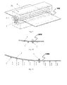
- the rolling device 1000 is provided with a row of flexible holding mechanisms 7 with a function of height adjustment in an inlet and an outlet for the sheet metal 4 being rolled respectively, the flexible holding mechanism may adopt a multi-point holding mechanism, a soft-shaft-based holding mechanism or a plurality of floating holding units for flexibly holding the sheet metal 4 in the inlet and the outlet thereof.
- Fig. 11 is a schematic view of a rolling device 2000 related to another embodiment of the present invention, and is a sectional schematic view in a direction parallel to a direction along which a sheet metal is passed through during a process in which the sheet metal is passed through a roll gap and is rolled.
- the rolling device 2000 adopts a plurality of rows of flexible holding mechanisms 7 with a function of height adjustment in a direction of the inlet and a direction of the outlet respectively. Also, a multi-point holding mechanism, a soft-shaft-based holding mechanisms or a plurality of floating holding units may be adopted for flexibly holding the sheet metal 4 in the inlet and the outlet.
- Fig. 12 is a structural exemplary view of a multi-point shape adjusting mechanism and a multi-point supporting mechanism related to the present invention.
- the structures of the multi-point shape adjusting mechanism and the multi-point supporting mechanism related to the present invention are not limited thereto.
- a forming roll 1 is restricted by an open shaft sleeve 8, which is embedded in a swing angle block 10; the swing angle block 10 is connected to a bracket 11 by a pin shaft 9, and the swing angle block 10 swings to ensure a consecutive and smooth flexure of the forming roll 1 in a shape adjustment process; and the bracket 11 is connected to an adjusting body 13 by a screw 12, and a shape adjusting lead screw 14 rotates to bring the adjusting body 13 and the bracket 11 to move up and down, thereby the functions of support and shape adjustment are achieved.
- the shaft sleeve 8 can be made of a material for sliding bearing, such as copper.
- the multi-point shape adjusting mechanism 3 controls the deflection of the forming roll 1 in a region supported by a multi-point supporting mechanism 2a, through the rotation of the shape adjusting lead screw 14.
- a plurality of multi-point shape adjusting mechanisms 3 are used for a multi-point control of the forming roll 1 in an axial direction, so that the deflection of the forming roll 1 can be adjusted according to need, and a non-uniform distribution of the roll gap between the upper forming roll 1a and the lower forming roll 1b in the axial direction is achieved.
- an oil groove and an oil passage may also be arranged on a contact surface between the shaft sleeve 8 and the forming roll 1.
- Fig. 13 is another structural exemplary view of a multi-point shape adjusting mechanism and a multi-point supporting mechanism related to the present invention.
- the structures of the multi-point shape adjusting mechanism and the multi-point supporting mechanism related to the present invention are not limited thereto.
- a forming roll 1 and two driving rolls 6 are restricted by an open shaft sleeve 8, which is embedded in a swing angle block 10; the swing angle block 10 is connected to a bracket 11 by a pin shaft 9, and the swing angle block 10 swings to ensure a consecutive and smooth flexure of the forming roll 1 in a shape adjustment process; and the bracket 11 is connected to an adjusting body 13 by a screw 12, and a shape adjusting lead screw 14 rotates to bring the adjusting body 13 and the bracket 11 to move up and down, thereby the functions of support and shape adjustment are achieved.
- a torque is applied to a roll body region of the forming roll 1 by the driving roll 6, so as to increase the rotational torque of the forming roll 1.
- the shaft sleeve 8 can be made of a material for sliding bearing, such as copper. In order to reduce friction, a lubricant can be added in the shaft sleeve 8.
- the multi-point shape adjusting mechanism 3 controls the deflection of the forming roll 1 in a region supported by a multi-point supporting mechanism 2a through the rotation of the shape adjusting lead screw 14.
- a plurality of multi-point shape adjusting mechanisms 3 are used for a multi-point control of the forming roll 1 in an axial direction, so that the deflection of the forming roll 1 can be adjusted according to need, and a non-uniform distribution of the roll gap between the upper forming roll 1a and the lower forming roll 1b in the axial direction is achieved.
- an oil groove and an oil passage may also be formed on a contact surface between the shaft sleeve 8 and the driving roll 6 and/or the forming roll 1.
- the number of the driving rolls is not limited to two.
- the present invention also provides a curved surface rolling method for three-dimensional curved surface forming of a sheet metal 4 by using the above rolling device, comprising a shape adjusting step and a rolling step.
- the shape adjusting step the upper forming roll 1a and/or the lower forming roll 1b are/is supported by a multi-point supporting mechanism 2a or an overall supporting mechanism 2b, and through the multi-point shape adjusting mechanism 3, the upper forming roll 1a and/or the lower forming roll 1b can be caused to a bending deformation, and a roll gap formed between the upper forming roll 1a and the lower forming roll 1b is distributed non-uniformly; and in the rolling step, the sheet metal 4 is passed through the roll gap, and the upper forming roll 1a and/or the lower forming roll 1b perform/perfomrs a roll forming process on the sheet metal 4.
- the shape adjusting step may be performed before the rolling step, the shape adjusting step and the rolling step may also be performed simultaneously, i.e., the deflections of the upper forming roll 1a and the lower forming roll 1b are changed and the shape of the roll gap between the forming rolls 1 is changed while the sheet metal 4 is rolled.
- three-dimensional curved surface forming or thin sheet rolling of the sheet metal 4 can be achieved simply, quickly and at a low cost.
- the overall displacing mechanism adjusts the roll gap without changing the flexure of the forming roll 1 before a forming process; or the overall displacing mechanism adjusts the roll gap without changing the flexure of the forming roll 1 during the forming process.
- thin sheet rolling or variable section sheet rolling can be achieved simply, quickly and at a low cost.
Landscapes
- Engineering & Computer Science (AREA)
- Mechanical Engineering (AREA)
- Physics & Mathematics (AREA)
- Geometry (AREA)
- Reduction Rolling/Reduction Stand/Operation Of Reduction Machine (AREA)
- Metal Rolling (AREA)
Applications Claiming Priority (4)
| Application Number | Priority Date | Filing Date | Title |
|---|---|---|---|
| CN2011103688715A CN102380532A (zh) | 2011-11-19 | 2011-11-19 | 用于板材三维曲面成形的曲面轧制装置和方法 |
| CN201110368823.6A CN102423777B (zh) | 2011-11-19 | 2011-11-19 | 一种曲面轧制方法 |
| CN201210238437XA CN102744253A (zh) | 2012-02-05 | 2012-07-11 | 板材轧制装置 |
| PCT/CN2012/084643 WO2013071867A1 (zh) | 2011-11-19 | 2012-11-15 | 轧制装置和方法 |
Publications (2)
| Publication Number | Publication Date |
|---|---|
| EP2781273A1 true EP2781273A1 (de) | 2014-09-24 |
| EP2781273A4 EP2781273A4 (de) | 2015-09-09 |
Family
ID=48428980
Family Applications (1)
| Application Number | Title | Priority Date | Filing Date |
|---|---|---|---|
| EP12848821.0A Withdrawn EP2781273A4 (de) | 2011-11-19 | 2012-11-15 | Walzvorrichtung und verfahren dafür |
Country Status (3)
| Country | Link |
|---|---|
| US (1) | US20140331730A1 (de) |
| EP (1) | EP2781273A4 (de) |
| WO (1) | WO2013071867A1 (de) |
Cited By (1)
| Publication number | Priority date | Publication date | Assignee | Title |
|---|---|---|---|---|
| WO2018147773A1 (en) * | 2017-02-07 | 2018-08-16 | Ingvest Ab | Method and arrangement for roll-forming a plane product with varying width |
Families Citing this family (1)
| Publication number | Priority date | Publication date | Assignee | Title |
|---|---|---|---|---|
| CN114472594B (zh) * | 2021-12-29 | 2024-03-08 | 泰安华鲁锻压机床有限公司 | 一种一体式金属板材矫平机 |
Family Cites Families (18)
| Publication number | Priority date | Publication date | Assignee | Title |
|---|---|---|---|---|
| BE637694A (de) * | 1962-09-21 | |||
| CA782796A (en) * | 1965-03-09 | 1968-04-16 | A. Baker William | Rolling mill |
| GB1279247A (en) * | 1968-09-30 | 1972-06-28 | United Eng Foundry Co | Crown control in a rolling mill or calender |
| US3762202A (en) * | 1971-10-18 | 1973-10-02 | W Sherwood | Rolling mill for flat-rolled products |
| JPS5024902B2 (de) * | 1972-01-28 | 1975-08-19 | ||
| JPS6057402B2 (ja) * | 1981-05-21 | 1985-12-14 | 三菱重工業株式会社 | 圧延機 |
| JPS57195519A (en) * | 1981-05-27 | 1982-12-01 | Mitsubishi Heavy Ind Ltd | Rolling mill |
| US4770017A (en) * | 1986-04-02 | 1988-09-13 | Agency Of Industrial Science And Technology | Apparatus for forming plate with a double-curved surface |
| FR2613641B1 (fr) * | 1987-04-09 | 1990-12-14 | Clecim Sa | Procede et installation de laminage d'un produit sous forme de bande, plus specialement une tole metallique ou un feuillard |
| AT403482B (de) * | 1996-01-29 | 1998-02-25 | Machner & Saurer Gmbh | Verfahren und vorrichtung zur gewinnung von flüssigem leichtmetall aus einer dispersen mischung |
| DE10036564C2 (de) * | 1999-08-03 | 2001-06-21 | Achenbach Buschhuetten Gmbh | Mehrwalzengerüst |
| JP2001353529A (ja) * | 2000-06-14 | 2001-12-25 | National Institute Of Advanced Industrial & Technology | フレキシブルロール成形装置 |
| CN2518613Y (zh) * | 2001-07-18 | 2002-10-30 | 史习 | 一种可调整辊缝变化速度的液压仿形轧制装置 |
| JP5611526B2 (ja) * | 2006-02-21 | 2014-10-22 | 吉林大学 | 3次元加工製品形成用のフレキシブル形成装置 |
| CN100999000B (zh) * | 2007-01-08 | 2010-09-29 | 吉林大学 | 使用可弯曲辊的三维曲面柔性成形装置 |
| CN100379501C (zh) * | 2006-07-21 | 2008-04-09 | 吉林大学 | 三维曲面柔性卷板装置 |
| CN102581005A (zh) * | 2012-02-05 | 2012-07-18 | 吉林大学 | 板材轧制装置 |
| CN102773269B (zh) * | 2012-08-16 | 2014-07-23 | 广西柳州银海铝业股份有限公司 | 板材轧制输送装置及其控制方法 |
-
2012
- 2012-11-15 WO PCT/CN2012/084643 patent/WO2013071867A1/zh not_active Ceased
- 2012-11-15 US US14/359,191 patent/US20140331730A1/en not_active Abandoned
- 2012-11-15 EP EP12848821.0A patent/EP2781273A4/de not_active Withdrawn
Cited By (1)
| Publication number | Priority date | Publication date | Assignee | Title |
|---|---|---|---|---|
| WO2018147773A1 (en) * | 2017-02-07 | 2018-08-16 | Ingvest Ab | Method and arrangement for roll-forming a plane product with varying width |
Also Published As
| Publication number | Publication date |
|---|---|
| WO2013071867A1 (zh) | 2013-05-23 |
| EP2781273A4 (de) | 2015-09-09 |
| US20140331730A1 (en) | 2014-11-13 |
Similar Documents
| Publication | Publication Date | Title |
|---|---|---|
| US8210014B2 (en) | Flexible forming device for forming three-dimensional shaped workpieces | |
| CN100999000B (zh) | 使用可弯曲辊的三维曲面柔性成形装置 | |
| US11484924B2 (en) | Device and method for forming shaft part by two-roller flexible skew rolling | |
| CN105188977B (zh) | 具有单独调节部和更换装置的矫直机 | |
| CN102380532A (zh) | 用于板材三维曲面成形的曲面轧制装置和方法 | |
| CN1589984A (zh) | 板材用轧机的轧制方法及板材用轧制设备 | |
| WO2016188305A1 (zh) | 二辊差速变曲率数控卷板机及其使用方法 | |
| CN112845607A (zh) | 一种超大直径比异步轧机以及板材轧制方法 | |
| CN107626781B (zh) | 一种可调四辊卷板机 | |
| CN111477834B (zh) | 一种电池极片辊压装置及辊压方法 | |
| EP2781273A1 (de) | Walzvorrichtung und verfahren dafür | |
| US3688540A (en) | Tube rolling mill employing a tapered mandrel and a cluster of rolls that each have specially designed tube contacting grooves | |
| CN101279336A (zh) | 三辊矫直机 | |
| CN106734193A (zh) | 一种变断面轧板冷轧机 | |
| CN202343672U (zh) | 用于板材三维曲面成形的曲面轧制装置 | |
| CN201030396Y (zh) | 使用可弯曲辊的三维曲面柔性成形装置 | |
| CN1974039A (zh) | 形状控制装置及形状控制方法 | |
| CN106270039B (zh) | 一种双曲度板辊弯成形装置 | |
| KR20140089986A (ko) | 금속관재의 강소성 가공방법 및 그 장치 | |
| CN2912857Y (zh) | 三维曲面柔性卷板装置 | |
| JP7224266B2 (ja) | 金属材の曲げ加工方法およびその装置 | |
| CN100379501C (zh) | 三维曲面柔性卷板装置 | |
| US20100326160A1 (en) | Continuously smoothly adjustable and self-aligning variable width roll forming apparatus | |
| CN102319781B (zh) | 可调节托辊装置及应用其的冷弯机构 | |
| CN100404159C (zh) | 钢筋矫直机的等曲率止转机构 |
Legal Events
| Date | Code | Title | Description |
|---|---|---|---|
| PUAI | Public reference made under article 153(3) epc to a published international application that has entered the european phase |
Free format text: ORIGINAL CODE: 0009012 |
|
| 17P | Request for examination filed |
Effective date: 20140618 |
|
| AK | Designated contracting states |
Kind code of ref document: A1 Designated state(s): AL AT BE BG CH CY CZ DE DK EE ES FI FR GB GR HR HU IE IS IT LI LT LU LV MC MK MT NL NO PL PT RO RS SE SI SK SM TR |
|
| DAX | Request for extension of the european patent (deleted) | ||
| RA4 | Supplementary search report drawn up and despatched (corrected) |
Effective date: 20150806 |
|
| RIC1 | Information provided on ipc code assigned before grant |
Ipc: B21D 5/08 20060101ALI20150731BHEP Ipc: B21B 1/22 20060101AFI20150731BHEP Ipc: B21B 13/00 20060101ALI20150731BHEP Ipc: B21B 27/02 20060101ALI20150731BHEP |
|
| 17Q | First examination report despatched |
Effective date: 20160804 |
|
| STAA | Information on the status of an ep patent application or granted ep patent |
Free format text: STATUS: EXAMINATION IS IN PROGRESS |
|
| STAA | Information on the status of an ep patent application or granted ep patent |
Free format text: STATUS: THE APPLICATION IS DEEMED TO BE WITHDRAWN |
|
| 18D | Application deemed to be withdrawn |
Effective date: 20161215 |