EP2781308A2 - Klammerausstoßende Heftvorrichtung - Google Patents
Klammerausstoßende Heftvorrichtung Download PDFInfo
- Publication number
- EP2781308A2 EP2781308A2 EP14161095.6A EP14161095A EP2781308A2 EP 2781308 A2 EP2781308 A2 EP 2781308A2 EP 14161095 A EP14161095 A EP 14161095A EP 2781308 A2 EP2781308 A2 EP 2781308A2
- Authority
- EP
- European Patent Office
- Prior art keywords
- staple
- main body
- type stapler
- ejecting type
- shift lever
- Prior art date
- Legal status (The legal status is an assumption and is not a legal conclusion. Google has not performed a legal analysis and makes no representation as to the accuracy of the status listed.)
- Withdrawn
Links
- 238000005381 potential energy Methods 0.000 claims abstract description 13
- 238000000034 method Methods 0.000 description 10
- 238000012986 modification Methods 0.000 description 1
- 230000004048 modification Effects 0.000 description 1
Images

Classifications
-
- B—PERFORMING OPERATIONS; TRANSPORTING
- B25—HAND TOOLS; PORTABLE POWER-DRIVEN TOOLS; MANIPULATORS
- B25C—HAND-HELD NAILING OR STAPLING TOOLS; MANUALLY OPERATED PORTABLE STAPLING TOOLS
- B25C5/00—Manually operated portable stapling tools; Hand-held power-operated stapling tools; Staple feeding devices therefor
- B25C5/10—Driving means
- B25C5/11—Driving means operated by manual or foot power
-
- B—PERFORMING OPERATIONS; TRANSPORTING
- B25—HAND TOOLS; PORTABLE POWER-DRIVEN TOOLS; MANIPULATORS
- B25C—HAND-HELD NAILING OR STAPLING TOOLS; MANUALLY OPERATED PORTABLE STAPLING TOOLS
- B25C5/00—Manually operated portable stapling tools; Hand-held power-operated stapling tools; Staple feeding devices therefor
- B25C5/02—Manually operated portable stapling tools; Hand-held power-operated stapling tools; Staple feeding devices therefor with provision for bending the ends of the staples on to the work
- B25C5/0207—Particular clinching mechanisms
-
- B—PERFORMING OPERATIONS; TRANSPORTING
- B25—HAND TOOLS; PORTABLE POWER-DRIVEN TOOLS; MANIPULATORS
- B25C—HAND-HELD NAILING OR STAPLING TOOLS; MANUALLY OPERATED PORTABLE STAPLING TOOLS
- B25C5/00—Manually operated portable stapling tools; Hand-held power-operated stapling tools; Staple feeding devices therefor
- B25C5/02—Manually operated portable stapling tools; Hand-held power-operated stapling tools; Staple feeding devices therefor with provision for bending the ends of the staples on to the work
- B25C5/0221—Stapling tools of the table model type, i.e. tools supported by a table or the work during operation
- B25C5/0235—Stapling tools of the table model type, i.e. tools supported by a table or the work during operation manually operated having a plunger cooperating with an anvil
-
- B—PERFORMING OPERATIONS; TRANSPORTING
- B25—HAND TOOLS; PORTABLE POWER-DRIVEN TOOLS; MANIPULATORS
- B25C—HAND-HELD NAILING OR STAPLING TOOLS; MANUALLY OPERATED PORTABLE STAPLING TOOLS
- B25C5/00—Manually operated portable stapling tools; Hand-held power-operated stapling tools; Staple feeding devices therefor
- B25C5/02—Manually operated portable stapling tools; Hand-held power-operated stapling tools; Staple feeding devices therefor with provision for bending the ends of the staples on to the work
- B25C5/0285—Hand-held stapling tools, e.g. manually operated, i.e. not resting on a working surface during operation
-
- B—PERFORMING OPERATIONS; TRANSPORTING
- B25—HAND TOOLS; PORTABLE POWER-DRIVEN TOOLS; MANIPULATORS
- B25C—HAND-HELD NAILING OR STAPLING TOOLS; MANUALLY OPERATED PORTABLE STAPLING TOOLS
- B25C5/00—Manually operated portable stapling tools; Hand-held power-operated stapling tools; Staple feeding devices therefor
- B25C5/16—Staple-feeding devices, e.g. with feeding means, supports for staples or accessories concerning feeding devices
- B25C5/1606—Feeding means
- B25C5/1617—Feeding means employing a spring-loaded pusher
-
- B—PERFORMING OPERATIONS; TRANSPORTING
- B25—HAND TOOLS; PORTABLE POWER-DRIVEN TOOLS; MANIPULATORS
- B25C—HAND-HELD NAILING OR STAPLING TOOLS; MANUALLY OPERATED PORTABLE STAPLING TOOLS
- B25C5/00—Manually operated portable stapling tools; Hand-held power-operated stapling tools; Staple feeding devices therefor
- B25C5/16—Staple-feeding devices, e.g. with feeding means, supports for staples or accessories concerning feeding devices
- B25C5/1606—Feeding means
- B25C5/1617—Feeding means employing a spring-loaded pusher
- B25C5/162—Feeding means employing a spring-loaded pusher with means for holding pusher out of position during re-loading
Definitions
- the present application relates to the technical field of staplers, and in particular to a staple-ejecting type stapler.
- Stapler is a tool for binding documents or paper and has been widely used in offices.
- a conventional stapler generally consists of a cover, a staple driver, a staple magazine, a staple pusher, an anvil, a base, and etc..
- a pressure is applied on the cover and is transmitted to the staple driver via the cover.
- a staple is pressed by the staple driver to pierce through a paper, and legs of the staple are bent by an anvil plate, thereby realizing the binding function of the stapler.
- the staple is directly driven by human power via the staple driver to pierce through the paper and to be bent, a user has to apply a large pressure on a normal stapler during binding, which may cause inconvenience in using.
- An embodiment of the present application provides a staple-ejecting type stapler, which can use an energy storing and energy releasing assembly to store energy by means of the lever principle and to generate an elastic force by releasing the elastic potential energy.
- a staple driver pushes a staple to pierce through paper, and legs of the staple are bent by an anvil plate, thereby realizing the binding function in a convenient and labor-saving manner.
- the staple-ejecting type stapler includes a top plate, a main body and a base, wherein the top plate is movably connected to the main body via a rotating shaft and configured to provide pressure for the main body; the main body has two ends, respectively, movably connected to the top plate and the base via a rotating shaft; the base is configured to support the main body and bend legs of a staple; wherein the main body includes an energy storing and energy releasing assembly, a staple magazine assembly and a staple pusher assembly, the energy storing and energy releasing assembly is arranged in the main body and is connected to the top plate, and is configured to store and release an elastic potential energy, the staple magazine assembly is configured to receive staples, and the staple pusher assembly is configured to push the staples; and the base includes a bottom plate, and an anvil plate fixed on the bottom plate and arranged opposite to a staple outlet.
- the energy storing and energy releasing assembly includes a staple driver, a shift lever, a reset torsion spring and an leaf spring;
- the staple driver is arranged in a guiding groove which is arranged in the main body and is perpendicular to the main body, and the staple driver has an upper portion provided with a small hole for cooperating with one end of the shift lever and a middle portion provided with a small hole for cooperating with the leaf spring;
- the shift lever is movably arranged inside the main body via a rotating shaft, and is provided with a small hole for cooperating with the rotating shaft and having an area lager than a cross-sectional area of the rotating shaft;
- the reset torsion spring has one end connected to one end of the shift lever and the top plate, and the other end connected to the main body; and the leaf spring has one end connected to the staple driver and the other end fixed on the main body.
- the staple magazine assembly includes a main body left plate, a main body right plate and a staple guiding groove; the main body left plate and the main body right plate are each provided with an inclined surface for cooperating with the shift lever; and the staple guiding groove is fixed inside the main body.
- the staple pusher assembly includes a pusher, a spring, a magazine shaft and a pressing member; the spring has one end connected to the pusher and the other end connected to the pressing member; the magazine shaft is fixedly connected to the pressing member; and the pusher is slidably connected to the magazine shaft.
- the base further includes an elastic member; and the elastic member has one end connected to the bottom plate and the other end connected to the main body, and is configured to keep a distance between the main body and the base when the staple-ejecting type stapler is in a non-operating state.
- the small hole on the shift lever is a small oval-shaped hole.
- an inclined angle of the inclined surface is ranged from 43° to 47° by defining a plane where a bottom surface of the main body is located in as a horizontal plane.
- the elastic member is a spring.
- the elastic member is a leaf spring.
- the embodiment of the present application has the following advantages.
- the energy storing and energy releasing assembly is arranged inside the main body and is consisted of the leaf spring, the shift lever 05, the staple driver and the reset torsion spring.
- the top plate is pressed by hand which applies a downward pressure on the top plate.
- the top plate exerts a downward pressure on the reset torsion spring by means of the lever principle to move the reset torsion spring downwards, so as to rotate the shift lever.
- the shift lever drives the staple driver at the other end of the shift lever to move upwards along the guiding groove, and when the end of the shift lever that is connected to the staple driver is moved to a top end of the inclined surface, the energy storing process of the leaf spring is completed.
- the shift lever and the staple driver are pressed by the top end of the inclined surface and thus are disengaged, and at this time, the leaf spring releases the stored elastic potential energy to drive the staple driver to move downwards.
- the staple is pushed by the staple driver to pierce through the paper, and legs of the staple are bent by the anvil plate, thereby completing the whole binding process.
- the leaf spring may store energy by pressing the top plate with hand by means of the lever principle, thus the binding operation may be completed easily without a large pressure.
- An embodiment of the present application provides a staple-ejecting type stapler, which can use an energy storing and energy releasing assembly to store energy by means of the lever principle and to generate an elastic force by releasing the elastic potential energy.
- a staple driver pushes a staple to pierce through paper, and legs of the staple are bent by an anvil plate, thereby realizing the binding function in a convenient and labor-saving manner.
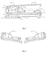
- the staple-ejecting type stapler includes a top plate 01, a main body and a base; the top plate 01 is movably connected to the main body via a rotating shaft and configured to provide pressure for the main body, the main body has two ends, respectively, movably connected to the top plate 01 and the base via a rotating shaft, and the base is provided to support the main body and bend legs of a staple.
- the main body includes an energy storing and energy releasing assembly, a staple magazine assembly and a staple pusher assembly.
- the energy storing and energy releasing assembly is arranged in the main body and is connected to the top plate, and is provided for storing and releasing an elastic potential energy.
- the staple magazine assembly is provided to receive staples, and the staple pusher assembly is provided to push a staple.
- the base includes a bottom plate 13, and an anvil plate 14 fixed on the bottom plate 13 and arranged opposite to a staple outlet.
- the energy storing and energy releasing assembly includes a staple driver 04, a shift lever 05, a reset torsion spring 06 and a leaf spring 07.
- the staple driver 04 is arranged in a guiding groove which is arranged in the main body and is perpendicular to the main body, and the staple driver 04 has an upper portion provided with a small hole for cooperating with one end of the shift lever 05 and a middle portion provided with a small hole for cooperating with the leaf spring 07.
- the shift lever 05 is movably arranged inside the main body via a rotating shaft, and is provided with a small hole for cooperating with the rotating shaft and having an area lager than a cross-sectional area of the rotating shaft.
- the reset torsion spring 06 has one end connected to one end of the shift lever 05 and the top plate 01, and the other end connected to the main body.
- the leaf spring 07 has one end connected to the staple driver and the other end fixed on the main body.
- the staple magazine assembly includes a main body left plate 02, a main body right plate 03 and a staple guiding groove 08; the main body left plate 02 and the main body right plate 03 are each provided with an inclined surface for cooperating with the shift lever 05; and the staple guiding groove 08 is fixed inside the main body.
- the staple pusher assembly includes a pusher 09, a spring 10, a magazine shaft 11 and a pressing member 12; the spring 10 has one end connected to the pusher 09 and the other end connected to the pressing member 12; the magazine shaft is fixedly connected to the pressing member 12; and the pusher 09 is slidably connected to the magazine shaft 11.
- the energy storing and energy releasing assembly is arranged inside the main body and is consisted of the leaf spring 07, the shift lever 05, the staple driver 04 and the reset torsion spring.
- the leaf spring when the staple-ejecting type stapler is in a non-operating state, the leaf spring may be in a natural straight state or in a curved state, i.e. having a certain amount of initial elastic potential energy, according to the requirement of design.
- the leaf spring has a certain amount of initial elastic potential energy
- the staple driver is located at a lower end of the guiding groove of the main body under the action of the leaf spring.
- the top plate 01 when the staple-ejecting type stapler is required to work, the top plate 01 is pressed by hand which applies a downward pressure on the top plate 01.
- the top plate 01 exerts a downward pressure on the reset torsion spring 06 by means of the lever principle to move the reset torsion spring 06 downwards, so as to rotate the shift lever 05.
- the shift lever 05 drives the staple driver 04 at the other end of the shift lever 05 to move upwards along the guiding groove, and when the end of the shift lever 05 that is connected to the staple driver 04 is moved to a top end of the inclined surface, the energy storing process of the leaf spring 07 is completed.
- the shift lever 05 and the staple driver 04 are pressed by the top end of the inclined surface and thus are disengaged, and at this time, the leaf spring 07 releases the stored elastic potential energy to drive the staple driver 04 to move downwards.
- the staple is pushed by the staple driver 04 to pierce through the paper, and legs of the staple are bent by the anvil plate 14, thereby completing the whole binding process.
- the base further includes an elastic member 15; the elastic member 15 has one end connected to the bottom plate 13 and the other end connected to the main body, and is configured to keep a certain distance between the main body and the base when the staple-ejecting type stapler is in the non-operating state.
- an inclined angle of the inclined surface is ranged from 43° to 47°, and is preferably 45°.
- the hole on the shift lever 05 is an oval-shaped hole.
- the elastic member 15 is a spring.
- the elastic member 15 is a leaf spring.
- the function of the inclined surface and the oval-shaped small hole is described below.
- the shift lever 05 is disengaged from the staple driver 04, and the leaf spring 07 can smoothly release the elastic potential energy, thereby completing the whole binding process.
- the small hole on the shift lever 05 is not limited to the oval-shaped hole in this embodiment, and may be small hole in other shapes, as long as the shift lever 05 is able to move forwards and rearwards along the rotation shaft.
- the position of the staple driver is defined as the forward direction and the position of the pressing member is defined as the rearward direction.
- the elastic member is configured to keep a certain distance between the main body and the base when the staple-ejecting type stapler is in the non-operating state.
- the elastic member is not limited to the spring shown in Figures of the present application, is not limited to the leaf spring, and can be made of other materials having the same characteristic.
- the embodiment of the present application has the following advantages.
- the energy storing and energy releasing assembly is arranged inside the main body and is consisted of the leaf spring 07, the shift lever 05, the staple driver 04 and the reset torsion spring.
- the top plate 01 is pressed by hand which applies a downward pressure on the top plate 01.
- the top plate 01 exerts a downward pressure on the reset torsion spring 06 by means of the lever principle to move the reset torsion spring 06 downwards, so as to rotate the shift lever 05.
- the shift lever 05 drives the staple driver 04 at the other end of the shift lever 05 to move upwards along the guiding groove, and when the end of the shift lever 05 that is connected to the staple driver 04 is moved to a top end of the inclined surface, the energy storing process of the leaf spring 07 is completed.
- the shift lever 05 and the staple driver 04 are pressed by the top end of the inclined surface and thus are disengaged, and at this time, the leaf spring 07 releases the stored elastic potential energy to drive the staple driver 04 to move downwards.
- the staple is pushed by the staple driver 04 to pierce through the paper, and legs of the staple are bent by the anvil plate 14, thereby completing the whole binding process.
- the leaf spring 07 may store energy by pressing the top plate 01 with hand by means of the lever principle, thus the binding operation may be completed easily without a large pressure.
Landscapes
- Engineering & Computer Science (AREA)
- Mechanical Engineering (AREA)
- Portable Nailing Machines And Staplers (AREA)
Applications Claiming Priority (1)
| Application Number | Priority Date | Filing Date | Title |
|---|---|---|---|
| CN2013100952039A CN103128709A (zh) | 2013-03-22 | 2013-03-22 | 一种射钉式订书机 |
Publications (2)
| Publication Number | Publication Date |
|---|---|
| EP2781308A2 true EP2781308A2 (de) | 2014-09-24 |
| EP2781308A3 EP2781308A3 (de) | 2015-04-08 |
Family
ID=48489491
Family Applications (1)
| Application Number | Title | Priority Date | Filing Date |
|---|---|---|---|
| EP14161095.6A Withdrawn EP2781308A3 (de) | 2013-03-22 | 2014-03-21 | Klammerausstoßende Heftvorrichtung |
Country Status (3)
| Country | Link |
|---|---|
| US (1) | US20140284369A1 (de) |
| EP (1) | EP2781308A3 (de) |
| CN (1) | CN103128709A (de) |
Cited By (1)
| Publication number | Priority date | Publication date | Assignee | Title |
|---|---|---|---|---|
| US11267117B2 (en) | 2018-09-14 | 2022-03-08 | ACCO Brands Corporation | Staple pusher assembly and method of installing same |
Families Citing this family (5)
| Publication number | Priority date | Publication date | Assignee | Title |
|---|---|---|---|---|
| SE536387C2 (sv) * | 2012-03-02 | 2013-10-01 | Isaberg Rapid Ab | Häftapparat med arrangemang för spänningssättning av ett elastiskt organ ingående i häftapparaten |
| US9687976B2 (en) | 2013-12-06 | 2017-06-27 | ACCO Brands Corporation | Stored energy stapler |
| US9446508B2 (en) | 2013-12-06 | 2016-09-20 | ACCO Brands Corporation | Stored energy stapler |
| CN104493789B (zh) * | 2014-12-19 | 2016-04-06 | 广州番禺通用文具制品厂有限公司 | 一种手握式订书机 |
| US20180207779A1 (en) * | 2017-01-20 | 2018-07-26 | Worktools, Inc. | Fastener magazine release system |
Family Cites Families (35)
| Publication number | Priority date | Publication date | Assignee | Title |
|---|---|---|---|---|
| US1919373A (en) * | 1931-02-28 | 1933-07-25 | Hansen Mfg Co A L | Stapling machine |
| US1927274A (en) * | 1932-04-16 | 1933-09-19 | Hansen Mfg Co A L | Stapling machine |
| US2107522A (en) * | 1936-03-12 | 1938-02-08 | Boston Wire Stitcher Co | Fastener-applying device |
| US2314848A (en) * | 1940-12-20 | 1943-03-23 | Hotchkiss Co E H | Fastener driving machine |
| GB823065A (en) * | 1956-05-16 | 1959-11-04 | Ofrex Ltd | Improvements relating to stapling tools |
| SE456660B (sv) * | 1987-03-03 | 1988-10-24 | Isaberg Ab | Anordning vid ett verktyg foer indrivning av ett faestelement, exempelvis en haeftklammer, i ett foeremaal |
| CN2086651U (zh) * | 1991-04-11 | 1991-10-16 | 陈海东 | 敲钉机 |
| US5931364A (en) * | 1997-06-25 | 1999-08-03 | Acme Staple Company, Inc. | Fastening tool for securing an object to a substrate |
| US6918525B2 (en) * | 2003-05-23 | 2005-07-19 | Worktools, Inc. | Spring energized desktop stapler |
| US20080011808A1 (en) * | 2003-05-23 | 2008-01-17 | Accentra, Inc. | Staple guide track |
| US7118019B2 (en) * | 2003-12-11 | 2006-10-10 | Worktools, Inc. | Jam resistant staple holding track for staplers |
| US7240819B2 (en) * | 2004-10-25 | 2007-07-10 | Chun Yuan Chang | Stapling device having rear housing opening |
| US7124924B2 (en) * | 2004-11-17 | 2006-10-24 | Worktools, Inc. | Desktop stapler striker/anvil alignment system |
| CN2743138Y (zh) * | 2004-11-19 | 2005-11-30 | 章峻源 | 扳机型订书机结构 |
| US7216791B1 (en) * | 2005-01-21 | 2007-05-15 | Worktools, Inc. | Spring energized stapler lever fulcrum in low position |
| EP1851011B1 (de) * | 2005-02-23 | 2015-12-23 | Worktools, Inc. | Heftmaschinensicherheitsvorrichtung zum begrenzen der bewegungen des schlagbolzens |
| US7124922B2 (en) * | 2005-02-23 | 2006-10-24 | Worktools, Inc. | Stapler safety guard |
| US20080302853A1 (en) * | 2005-02-24 | 2008-12-11 | Joel Marks | Contoured base for desktop stapler |
| US7681771B2 (en) * | 2005-06-17 | 2010-03-23 | Acco Brands Usa Llc | Stapler |
| US7395955B2 (en) * | 2006-01-06 | 2008-07-08 | Staples The Office Superstore, Llc | Stapler |
| US7540400B2 (en) * | 2006-01-06 | 2009-06-02 | Staples The Office Superstore, Llc | Stapler having a moveable strike plate with lockout mechanism |
| US7404507B2 (en) * | 2006-01-30 | 2008-07-29 | Worktools, Inc. | High-start spring energized stapler |
| CN1948022A (zh) * | 2006-11-02 | 2007-04-18 | 廖金志 | 储能式钉书机 |
| CN101177082A (zh) * | 2006-11-08 | 2008-05-14 | 洪立业 | 强力打钉订书机 |
| US7299960B1 (en) * | 2006-12-20 | 2007-11-27 | Worktools, Inc. | Mini desktop stapler |
| US7950558B2 (en) * | 2007-11-05 | 2011-05-31 | Worktools, Inc. | Spring actuated pliers stapler |
| CN101168333B (zh) * | 2007-11-05 | 2011-01-12 | 廖金志 | 自调钉针力的储能式订书机 |
| TW200920563A (en) * | 2007-11-12 | 2009-05-16 | Jann Yei Industry Co Ltd | A staple gun safety device |
| US7665644B2 (en) * | 2007-12-14 | 2010-02-23 | Chih-Wei Hu | Stapler |
| US7669745B2 (en) * | 2008-01-22 | 2010-03-02 | Chun-Yuan Chang | Dual protective device of a heavy-duty stapler |
| US7980438B2 (en) * | 2009-01-27 | 2011-07-19 | Jui-Yuan Lin | Latch assembly for a staple gun |
| TW201038371A (en) * | 2009-04-16 | 2010-11-01 | Apex Mfg Co Ltd | Labor saving stapler |
| CN102079079B (zh) * | 2009-12-01 | 2012-10-03 | 丰民金属工业股份有限公司 | 安全钉枪 |
| US8052022B2 (en) * | 2009-12-16 | 2011-11-08 | Worktools, Inc. | Leveraged action stapler |
| CN203330989U (zh) * | 2013-03-22 | 2013-12-11 | 广州番禺通用文具制品厂有限公司 | 一种射钉式订书机 |
-
2013
- 2013-03-22 CN CN2013100952039A patent/CN103128709A/zh active Pending
- 2013-12-02 US US14/093,534 patent/US20140284369A1/en not_active Abandoned
-
2014
- 2014-03-21 EP EP14161095.6A patent/EP2781308A3/de not_active Withdrawn
Non-Patent Citations (1)
| Title |
|---|
| None |
Cited By (1)
| Publication number | Priority date | Publication date | Assignee | Title |
|---|---|---|---|---|
| US11267117B2 (en) | 2018-09-14 | 2022-03-08 | ACCO Brands Corporation | Staple pusher assembly and method of installing same |
Also Published As
| Publication number | Publication date |
|---|---|
| US20140284369A1 (en) | 2014-09-25 |
| EP2781308A3 (de) | 2015-04-08 |
| CN103128709A (zh) | 2013-06-05 |
Similar Documents
| Publication | Publication Date | Title |
|---|---|---|
| EP2781308A2 (de) | Klammerausstoßende Heftvorrichtung | |
| US20100059568A1 (en) | Low-effort, two-stage stapler | |
| US20120175397A1 (en) | Flat-clinch stapler | |
| CA2807914C (en) | Fastening tool assembly | |
| WO2009031666A1 (ja) | ステープラ | |
| JP5906925B2 (ja) | 用紙処理装置 | |
| CN1988986B (zh) | 订书机以及订书钉装订盒 | |
| US8740032B2 (en) | Electric stapler | |
| CN207256156U (zh) | 一种多功能钉枪 | |
| US20140231487A1 (en) | Stapler | |
| US20070023473A1 (en) | Spring-powered stapler | |
| US20120187617A1 (en) | Finger pinch preventing hand-held quick-clamping device | |
| US2658197A (en) | Stapling machine | |
| US3398872A (en) | Hand-operated stapler | |
| CN209919815U (zh) | 一种压线钉枪 | |
| CN201201376Y (zh) | 省力订书机 | |
| US2228778A (en) | Stapling machine | |
| CN110541903A (zh) | 蓄力扭簧及具有所述蓄力扭簧的钉枪 | |
| EP1577061B1 (de) | Elektrischer Heftapparat | |
| CN110405695A (zh) | 一种压线钉枪 | |
| JP2003136426A (ja) | ステープラー内のステープル形成機構 | |
| US2977599A (en) | Vertical drop stapling machine | |
| JP2012045653A (ja) | ステープラ | |
| US20140353356A1 (en) | Stapler for Use with Distinctively Shaped Staples | |
| CN205800562U (zh) | 具活动式压针机构的订书机 |
Legal Events
| Date | Code | Title | Description |
|---|---|---|---|
| PUAI | Public reference made under article 153(3) epc to a published international application that has entered the european phase |
Free format text: ORIGINAL CODE: 0009012 |
|
| 17P | Request for examination filed |
Effective date: 20140321 |
|
| AK | Designated contracting states |
Kind code of ref document: A2 Designated state(s): AL AT BE BG CH CY CZ DE DK EE ES FI FR GB GR HR HU IE IS IT LI LT LU LV MC MK MT NL NO PL PT RO RS SE SI SK SM TR |
|
| AX | Request for extension of the european patent |
Extension state: BA ME |
|
| RIN1 | Information on inventor provided before grant (corrected) |
Inventor name: DAI, CHANGHAI Inventor name: DUAN, ZHONGMIN Inventor name: YANG, XIAORONG |
|
| PUAL | Search report despatched |
Free format text: ORIGINAL CODE: 0009013 |
|
| AK | Designated contracting states |
Kind code of ref document: A3 Designated state(s): AL AT BE BG CH CY CZ DE DK EE ES FI FR GB GR HR HU IE IS IT LI LT LU LV MC MK MT NL NO PL PT RO RS SE SI SK SM TR |
|
| AX | Request for extension of the european patent |
Extension state: BA ME |
|
| RIC1 | Information provided on ipc code assigned before grant |
Ipc: B25C 5/02 20060101AFI20150302BHEP Ipc: B25C 5/16 20060101ALI20150302BHEP Ipc: B25C 5/11 20060101ALI20150302BHEP |
|
| STAA | Information on the status of an ep patent application or granted ep patent |
Free format text: STATUS: THE APPLICATION IS DEEMED TO BE WITHDRAWN |
|
| 18D | Application deemed to be withdrawn |
Effective date: 20161001 |