EP2781685A2 - Soupape à écoulement libre - Google Patents
Soupape à écoulement libre Download PDFInfo
- Publication number
- EP2781685A2 EP2781685A2 EP20140165023 EP14165023A EP2781685A2 EP 2781685 A2 EP2781685 A2 EP 2781685A2 EP 20140165023 EP20140165023 EP 20140165023 EP 14165023 A EP14165023 A EP 14165023A EP 2781685 A2 EP2781685 A2 EP 2781685A2
- Authority
- EP
- European Patent Office
- Prior art keywords
- interface
- moving part
- valve according
- valve
- esp
- Prior art date
- Legal status (The legal status is an assumption and is not a legal conclusion. Google has not performed a legal analysis and makes no representation as to the accuracy of the status listed.)
- Withdrawn
Links
- 239000012530 fluid Substances 0.000 claims abstract description 95
- 238000004519 manufacturing process Methods 0.000 claims abstract description 48
- 230000004888 barrier function Effects 0.000 claims abstract 2
- 239000000463 material Substances 0.000 claims description 8
- 238000005266 casting Methods 0.000 description 12
- 238000007789 sealing Methods 0.000 description 10
- 239000007787 solid Substances 0.000 description 10
- 238000004891 communication Methods 0.000 description 9
- 238000009434 installation Methods 0.000 description 7
- 238000000034 method Methods 0.000 description 7
- 230000000694 effects Effects 0.000 description 6
- 239000012717 electrostatic precipitator Substances 0.000 description 6
- 230000000670 limiting effect Effects 0.000 description 6
- 230000015572 biosynthetic process Effects 0.000 description 5
- 238000003754 machining Methods 0.000 description 5
- 206010010904 Convulsion Diseases 0.000 description 4
- 230000002411 adverse Effects 0.000 description 4
- XLYOFNOQVPJJNP-UHFFFAOYSA-N water Substances O XLYOFNOQVPJJNP-UHFFFAOYSA-N 0.000 description 4
- 230000008901 benefit Effects 0.000 description 3
- 229930195733 hydrocarbon Natural products 0.000 description 3
- 150000002430 hydrocarbons Chemical class 0.000 description 3
- 230000008569 process Effects 0.000 description 3
- 230000002829 reductive effect Effects 0.000 description 3
- 239000004215 Carbon black (E152) Substances 0.000 description 2
- 238000010276 construction Methods 0.000 description 2
- 238000005086 pumping Methods 0.000 description 2
- 230000000717 retained effect Effects 0.000 description 2
- 239000004576 sand Substances 0.000 description 2
- 230000007704 transition Effects 0.000 description 2
- 241000190019 Guaiacum Species 0.000 description 1
- 235000004440 Guaiacum sanctum Nutrition 0.000 description 1
- 235000010931 Mesua ferrea Nutrition 0.000 description 1
- 235000005704 Olneya tesota Nutrition 0.000 description 1
- 240000007909 Prosopis juliflora Species 0.000 description 1
- 235000008198 Prosopis juliflora Nutrition 0.000 description 1
- 230000032683 aging Effects 0.000 description 1
- 230000004075 alteration Effects 0.000 description 1
- 238000002485 combustion reaction Methods 0.000 description 1
- 239000004035 construction material Substances 0.000 description 1
- 230000001419 dependent effect Effects 0.000 description 1
- 238000010612 desalination reaction Methods 0.000 description 1
- 230000001627 detrimental effect Effects 0.000 description 1
- 238000001914 filtration Methods 0.000 description 1
- 230000005484 gravity Effects 0.000 description 1
- 238000005304 joining Methods 0.000 description 1
- 230000001737 promoting effect Effects 0.000 description 1
- 238000011084 recovery Methods 0.000 description 1
- 230000008439 repair process Effects 0.000 description 1
- 230000002441 reversible effect Effects 0.000 description 1
- 239000011435 rock Substances 0.000 description 1
- 230000003068 static effect Effects 0.000 description 1
Images






Classifications
-
- E—FIXED CONSTRUCTIONS
- E21—EARTH OR ROCK DRILLING; MINING
- E21B—EARTH OR ROCK DRILLING; OBTAINING OIL, GAS, WATER, SOLUBLE OR MELTABLE MATERIALS OR A SLURRY OF MINERALS FROM WELLS
- E21B43/00—Methods or apparatus for obtaining oil, gas, water, soluble or meltable materials or a slurry of minerals from wells
- E21B43/12—Methods or apparatus for controlling the flow of the obtained fluid to or in wells
- E21B43/121—Lifting well fluids
- E21B43/122—Gas lift
- E21B43/123—Gas lift valves
-
- E—FIXED CONSTRUCTIONS
- E21—EARTH OR ROCK DRILLING; MINING
- E21B—EARTH OR ROCK DRILLING; OBTAINING OIL, GAS, WATER, SOLUBLE OR MELTABLE MATERIALS OR A SLURRY OF MINERALS FROM WELLS
- E21B34/00—Valve arrangements for boreholes or wells
- E21B34/06—Valve arrangements for boreholes or wells in wells
- E21B34/08—Valve arrangements for boreholes or wells in wells responsive to flow or pressure of the fluid obtained
Definitions
- FFV Free Flow Valve
- Well - meaning water well or hydrocarbon well.
- Fluid - meaning hydrocarbon or water.
- Distance - meaning a distance between fifty feet and twenty thousand feet or between fifteen metres and six thousand metres.
- Lift - meaning moving fluid a distance from below ground level or from below sea bed level or from beneath the bed level of another body of water to a location.
- Location meaning a location determined by the purpose of the associated lift operation where the location can be a land based or sea based rig such as an oil rig, or ship, or water treatment plant such as filtration or/and desalination, or reservoir, or sub-terrain or sub-sea installation such as a valve, or instrumentation, or a further pumping means, and the like as known by those skilled in the art.
- Natural lift meaning a well's ability to lift by natural well pressure alone unassisted by artificial lift.
- Downhole pump - meaning a fluid pumping device installed in a well to provide artificial lift.
- Production meaning an acceptable quantity of fluid from a well to a location in an acceptable time.
- First interface meaning a first seal face that defines a fluid path through the FFV between the annulus with the associated production tubing.
- Second interface meaning a second seal face that defines a fluid path through the FFV between the ESP with the associated production tubing.
- String or production tubing - means the production carrying tubing to which the ESP and valve are connected.
- Casing meaning the inner diameter of the well bore often defined by the inner diameter of a series of tubular components inserted into the well.
- Annulus - defines the space between the casing and the outside diameter of the FFV or/and ESP.
- Single moving part or single sealing member meaning the FFV's only moving part and whose function it is to form a seal with two seal faces but not simultaneously. Wherein each said seal is achieved only by the single moving part self aligning with the associated seal face.
- the single sealing member/moving part does not house or incorporate a rotational or linear axis and does not move between the two seal faces via an articulation.
- Natural lift production is usually at its greatest when the well is new. Thereafter, natural lift production usually dissipates with the passage of time. Eventually the well loses its ability to produce by natural lift. Thereafter, artificial lift is the only way to satisfy production. Since production is increasingly dependent on ageing wells the need for artificial lift is consequently increasing.
- ESPs are a very common means of artificial lift and are particularly relevant to the FFV.
- the FFV is the invention herein described.
- ESPs are considered to be a highly efficient means of artificial lift and are capable of high production rates with lighter hydrocarbons with a low sand and/or low solid content. It is generally accepted that ESP production can exceed other means of artificial lift within the fluid viscosity range that ESPs operate.
- ESPs attach to the string and are independently powered from, typically, the surface by a power cable which extends along the string to the motor part of the ESP.
- ESPs lift fluid from the annulus and in the process cause a continuous pressure differential between the annulus and formation. The pressure differential allows more fluid to re-charge the annulus from the formation due to the formation pressure overcoming the reduced annulus pressure.
- ESPs are often installed but not used before the associated well stops producing by natural lift. Thereafter the ESP can be turned on without requiring a second installation. The alternative would require a first installation without an ESP until the associated well stopped producing by natural lift, then the removal of the first installation, then a second installation that included an ESP. Whilst a well is producing by natural lift the associated installed ESP is not used. This saves the ESP from needless wear and prolongs the ESP's life which reduces installation costs and maximises the ESP's future production duration.
- the FFV In the interest of reliability the FFV is not designed to overcome all of the ESP problems. Instead the FFV's scope is limited to only overcoming the most common ESP problems (a) (b) (b1) (b2) (b3), the FFV's first goal.
- the FFV's limited scope allows for a much simpler and thereby inherently more reliable design by comparison to the prior art, the FFV's second goal. Whereby, the FFV's simplicity minimises production costs, the FFV's third goal.
- the FFV exchanges scope for reliability and cost efficiency by comparison to the prior art.
- the FFV employs a single sealing member that performs its sealing function by the sole parameter of self alignment with either of the two sealing faces.
- the sealing member does not need said additional parameters to move from one seal face to the other seal face.
- additional parameters such as one or more rotational or/and linear axes
- the sealing member also does not need said additional parameters to move from one seal face to the other seal face.
- the absence of said additional parameters reduces the opportunity for silt to impair the sealing function by getting trapped between the static and moving parts of the said additional parameters, thus promoting the FFV's second goal.
- the fewer moving parts the fewer the associated precision tolerances which reduces manufacturing costs which promotes the FFV's third goal.
- the FFV's design philosophy is based on opening the fluid path between the ESP and string before fully closing the fluid path between the annulus and string and vice versa.
- the FFV has one moving part that moves between a first position and a second position.
- the first position is synonymous with the ESP not being operated and the well having natural lift.
- the second position is synonymous with the ESP being operated. However, the second position is also synonymous with the ESP being turned off to leave a column of fluid above the FFV in the string generating greater pressure in the FFV than from the natural well pressure through the FFV to keep the moving part in the second position.
- the moving part In the first position the moving part forms a first interface. In the second position the moving part forms a second interface. The moving part cannot simultaneously form both the first and second interfaces.
- the first interface discommunicates the ESP outlet from the string and simultaneously communicates only the annulus to the string.
- the moving part is held in the first position by the natural lift pressure via the annulus being greater than the natural lift pressure via the ESP.
- the multitude of impellers and diffusers in the ESP pump restricts natural lift through the ESP pump and thereby reduces the natural lift pressure through the ESP pump by comparison to the unrestricted natural lift pressure via the annulus. This pressure differential keeps the moving part in the first position when the ESP is turned off, i.e. not being operated in a well having natural lift.
- the second interface only communicates the ESP outlet with the string and simultaneously discommunicates the annulus from the string when the ESP is being used.
- the moving part is held in the second position by the artificial lift pressure overcoming the annulus pressure. This pressure differential keeps the moving part in the second position when the ESP is turned on, i.e. being operated.
- the moving part After turning off the ESP the moving part remains in the second position whilst the pressure in the FFV generated by the fluid held in the string above the FFV exceeds the pressure in the FFV from natural lift.
- the fluid held in the string flows back into the annulus through the ESP pump which reduces the pressure in the FFV from the fluid column whilst the annulus pressure increases to match the formation pressure. Should the natural lift pressure in the FFV exceed the pressure in the FFV from the fluid column the moving part will move from the second position to the first position.
- the moving part After the ESP has been turned off the moving part is moved from the second position to the first position in three stages. Firstly by breaking the second interface when the natural lift pressure via the annulus overcomes both the natural lift pressure via the ESP and the string fluid column pressure. Secondly by gravity, unless the FFV is horizontal or to any degree inverted, and by the natural lift fluid flow via the annulus carrying the moving part to the first position from the second position. Thirdly by the moving part forming the first interface by the natural lift pressure via the annulus overcoming the natural lift pressure via the ESP.
- the FFV is positioned either between the ESP outlet and string or along the string from the ESP.
- the FFV is a Free Flow Valve in that the moving part can move between the first position and the second position and vice versa by the direction of fluid passing through the FFV either via natural lift or via artificial lift.
- the FFV comprises four separate components which are housing (1) shoulder (2) locking ring (3) moving part (4).
- Housing (1) is a machined casting.
- shoulder (2), locking ring (3), moving part (4) can each be either machined from billet or a machined casting.
- Moving part (4) is spherical and of solid construction.
- Shoulder (2) and locking ring (3) are both positioned via a thread to internal diameter (5) of housing (1).
- Shoulder (2) butts-up against step (6) as shown by detailed view Figure 1a of Figure 1 .
- Locking ring (3) butts-up against shoulder (2) to prevent shoulder (2) from disuniting from step (6).
- the purpose of shoulder (2) being a removable component is to allow moving part (4) to be assembled.
- shoulder (7) in the detailed view Figure 3a of Figure 3 is an integral part of housing (1). Casting can be a cost effective manufacturing process when unit numbers are sufficient to justify the making of a casting mould.
- Figures 6 , 7 , 8 , 9 show a press fit or interference fit assembly method and Figure 24 shows an assembly method employing a threaded housing (1201).
- the FFV comprises three separate components which are, outer housing (101), moving part (104), inner housing (108).
- Figure 9 shows the three components disassembled with only outer housing (101) in cross section. Each of these three components can be either machined from billet or a machined casting.
- Moving part (104) is spherical and of solid construction.
- Shoulder (102) is an integral part of outer housing (101) as shown by detailed view Figure 6a of Figure 6 .
- Inner housing (108) is positioned via an interference fit to inner diameter (109) of outer housing (101) where the interference fit can be between tapered or parallel sides.
- Inner housing (108) also butts-up against shoulder (102) as shown by detailed view Figure 6a of Figure 6 .
- Figure 8 shows section BB of Figure 6 .
- Inner housing (108) can be rotated using a torque applying tool fashioned to fit into ports (111).
- Inner housing (108) is a separate component to allow outer housing (101) to be either a machined casting or machined from billet or from tubing.
- moving part (104) can be assembled in the process of assembling inner housing (108) which negates the need for shoulder (102) to be a removable component. Machining from billet or from tubing is more cost effective than casting when the unit numbers are not sufficient to justify the cost of making a casting mould.
- component alterations can be made quicker and cheaper when machining from billet or from tubing than can be made via a casting manufacturing process.
- outer housing (101) can be further fixed to inner housing (108) by one or more removable dowels (112).
- removable dowels (112) traverse the interference fit between outer housing (101) and inner housing (108) without breaking into any of the ports (110), (111), or into any of the chambers (113), (114), (115), (116).
- Preferably removable dowels (112) each have one through hole which is threaded. The through hole prevents air getting trapped in the dowels blind location hole. Otherwise trapped air will expand with the downhole heat which might push the dowel out. The edge of the dowel's blind hole can be swaged to retain the dowel.
- the through thread of dowel (112) provides a means by which the dowel can be removed to dissemble the FFV.
- moving part (4) is shown in the first position. In the first position moving part (4) forms a first interface (17) with shoulder (2) as shown in Figure 1a . In Figure 1a interface (17) is shown with a small gap between moving part (4) and shoulder (2). This gap is only present in Figure 1a to distinguish moving part (4) from shoulder (2) but in practice no such gap would exist when interface (17) is formed. Interface (17) forms a seal that for all practicable purposes prevents fluid from crossing from chamber (13) to chamber (14).
- Figure 6 moving part (104) is shown in the first position. In the first position moving part (104) forms a first interface (117) with shoulder (102) as shown in Figure 6a . In Figure 6a interface (117) is shown with a small gap between moving part (104) and shoulder (102).
- moving part (4) is shown in the second position. In the second position moving part (4) forms a second interface (18) with shoulder (7) as shown in Figure 3a .
- interface (18) is shown with a small gap between moving part (4) and shoulder (7). This gap is only present in Figure 3a to clearly identify moving part (4) and shoulder (7) from each other but in practice no such gap would exist when interface (18) is formed.
- Second interface (18) forms a seal that for all practicable purposes prevents fluid from crossing from chamber (15) to chamber (14).
- Figure 7 moving part (104) is shown in the second position. In the second position moving part (104) forms a second interface (118) with shoulder (107) as shown in Figure 7a .
- Housing (1)/(101) respectively contains, pump discharge chamber (13)/(113) transfer chamber (14)/(114) annulus chamber (15)/(115) and valve discharge chamber (16)/(116).
- Pump discharge chamber (13)/(113) are respectively defined by the space between the ESP outlet and first interface (17)/(117).
- Transfer chambers (14)/(114) are respectively defined by the space between first interface (17)/(117) and second interface (18)/(118) excluding valve discharge ports (11)/(111).
- Annulus chambers (15)/(115) are respectively defined by the space between second interface (18)/(118) and cap (19)/(119) excluding annulus ports (10)/(110).
- Caps (19)/(119) dictate that the fluid path exiting the FFV from annulus chambers (15)/(115) is respectively limited to annulus ports (10)/(110).
- Valve discharge chambers (16)/(116) are respectively defined by the space between caps (19)/(119) and the string excluding valve discharge ports (11)/(111).
- entry to and exit from pump discharge chamber (13)/(113) is only via the ESP outlet
- entry to and exit from transfer chamber (14)/(114) is only via valve discharge ports (11)/(111) and annulus chamber (15)/(115)
- entry to and exit from annulus chamber (15)/(115) is only via annulus ports (10)/(110) and transfer chamber (14)/(114)
- entry to and exit from valve discharge chamber (16)/(116) is only from valve discharge ports (11)/(111) and the string.
- Communication between annulus chamber (15)/(115) and the annulus is only via annulus ports (10)/(110).
- Communication between valve discharge chamber (16)/(116) and transfer chamber (14)/(114) is only via valve discharge ports (11)/(111).
- Communication between transfer chamber (14)/(114) and annulus chamber (15)/(115) is only across second interface (18)/(118).
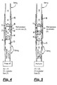
- Figure 4 shows a simplified version of Figure 1 installed between the string and the ESP outlet whereby, the string each side of the FFV is shown in a non hatched cross section along its longitudinal centre line.
- the arrows in Figure 4 show the fluid path when the FFV is installed in a naturally producing well but when the ESP is not operating.
- the fluid from the annulus enters transfer chamber (14) through the aperture of shoulder (7) from annulus chamber (15) via annulus ports (10) forcing moving part (4) to form first interface (17) with shoulder (2), i.e. first position, which diverts the fluid from transfer chamber (14) into valve discharge ports (11) and then into valve discharge chamber (16) and then into the string.
- the flow path shown in Figure 4 equally applies to Figure 6 .
- the most common ESP problems are overcome by moving part (4)/(104) disconnecting pump discharge chamber (13)/(113) from transfer chamber (14)/(114) by forming first interface (17)/(117).
- Figure 5 shows Figure 4 but where the arrows show the fluid path when the ESP is turned on and generating artificial lift.
- the fluid from the ESP outlet enters transfer chamber (14) through shoulder (2) from pump discharge chamber (13) and forces moving part (4) to form second interface (18) with shoulder (7), i.e. second position, which diverts the fluid from transfer chamber (14) to the string via valve discharge ports (11) and valve discharge chamber (16).
- the flow path shown in Figure 5 equally applies to Figure 7 .
- Moving part (4)/(104) is held in the first position by the pressure in transfer chamber (14)/(114) being greater than the pressure in pump discharge chamber (13/(113). Moving part (4)/(104) is disunited from the first position by the pressure in pump discharge chamber (13)/(113) being greater than the pressure in transfer chamber (14/(114). Moving part (4)/(104) is held in the second position by the pressure in transfer chamber (14)/(114) being greater than the pressure in annulus chamber (15)/(115). Moving part (4)/(104) is disunited from the second position by the pressure in annulus chamber (15)/(115) being greater than the pressure in transfer chamber (14)/(114).
- pump discharge chamber (13)/(113) transfer chamber(14)/(114) annulus chamber (15)/(115) valve discharge chamber (16)/(116) annulus ports (10)/(110) valve discharge ports(11)/(111) shoulders (2)/(102) (7)/(107) all have the largest possible through cross sectional area to maximise fluid flow through the FFV.
- FFV's construction material, relating to the various cross sections of housing (1) outer housing (101) inner housing (108) cannot be so thin that the structural integrity of any of the said cross sections is jeopardised.
- pump discharge chamber (13)/(113) transfer chamber(14)/(114) annulus chamber (15)/(115) valve discharge chamber (16)/(160) annulus ports (10)/(110) valve discharge ports (11)/(111) shoulders (2)/(102) (7)/(107) first interface (17)/(117) second interface (18)/(118), are preferably all concentrically aligned with their associated housing (1) outer housing (101) inner housing (108).
- outer housing (101) inner housing (108) To maintain the same fluid flow with the alternative of an eccentric alignment would require the FFV's constructional material to be too thin to maintain structural integrity.
- To maintain said structural integrity with the alternative of an eccentric alignment would require a smaller cross sectional area through the FFV which restricts fluid flow.
- the cross sectional area of the artificial lift fluid path through the FFV can differ from the cross sectional area of the natural lift fluid path through the FFV.
- the cross sectional area of the fluid path through the FFV for artificial lift can be larger than the cross sectional area of the fluid path through the FFV specific to natural lift.
- the artificial lift fluid path comprises, pump discharge chamber (13)/(113) shoulder (2)/(102) transfer chamber (14)/(114) valve discharge ports (11)/(111) valve discharge chamber (16)/(116)
- the associated fluid path specific to natural lift comprises, annulus port (10)/(110) annulus chamber (15)/(115) shoulder (7)/(107).
- the cross sectional area of the fluid path through the FFV for natural lift can be larger than the cross sectional area of the fluid path through the FFV specific to artificial lift.
- the natural lift fluid path comprises, annulus ports (10)/(110) annulus chamber (15)/(115) shoulder (7)/(107) transfer chamber (14)/(114) valve discharge ports (11)/(111) valve discharge chamber (16)/(116), and the associated fluid path specific to artificial lift comprises, pump discharge chamber (13)/(113) shoulder (2)/(102).
- first interface (17)/(117) and of second interface (18)/(118) The wider the cross section of first interface (17)/(117) and of second interface (18)/(118) the greater the chance of first interface (17)/(117) and second interface (18)/(118) being hindered from sealing properly by solids carried by the fluid flow.
- the FFV employs the smallest practicable cross section to form first interface (17/(117) and to form second interface (18)/(118).
- first interface (17)/(117) and second interface (18)/(118) are each formed between the convex surface of a sphere segment and the concave surface of a cone segment as shown in Figure 1a (17) Figure 3a (18) Figure 6a (117) Figure 7a (118).
- the convex surface is carried by the entire surface of moving part (4)/(104)/(204) which is a sphere.
- the convex surface is respectively carried at each end of moving part (304), (404), (504), (604), (704), (804), (904), (1004), (1104), in the form of a sphere segment.
- Figure 1a , Figure 3a , Figure 6a , Figure 7a the shown perpendicular cross section to the convex surface is straight. However, the said cross section could be convex as shown in Figure 22 or concave as shown in Figure23 .
- the concave cross section in Figure 23 can have the same radius as the associated moving part's spherical section that forms the interface as per Figure 23 , or where the concave cross section in Figure 23 has either a larger or smaller radius than the associated moving part's spherical section that forms the interface.
- first interface (17)/(117) and second interface (18)/(118) are between a spherical segment and a cone segment
- said interfaces can each be formed between the convex surface of a cone carried by the single moving part and the concave surface of another cone fixed to a non moving part of the valve.
- a component that moves requires a gap between itself and adjacent components in order to move. Without said gap moving components cannot move freely.
- the more moving components and/or more precision gaps the more risk of seizure.
- the greater the distance a moving component's movement is guided by a precision gap the greater is the need for the precision gap's axial accuracy over the moving component's movement in addition to the dimensional accuracy of the gap.
- the gap's axial accuracy further increases manufacturing costs.
- the axial accuracy can be between two different diameters as with, for example, the exhaust and inlet poppet valves of an internal combustion engine or between more than two different diameters.
- precision machining is required between the, valve stem and valve guide, valve face and valve seat, and also require precision alignment between the, valve guide and valve seat, valve stem and valve face.
- the FFV employs one moving component whose movement does not require a precision gap which negates issues about gap surface area, gap numbers, and gap axial alignment.
- a spherical segment or segments for moving part (4)-(1104) permits the entire movement of moving part (4)-(1104) between first interface (17)/(117) and second interface (18)/(118) without the need for precision axial accuracy because the spherical segments allow moving part (4)-(1104) to be misaligned longitudinally between first interface (17)/(117) and second interface (18)/(118) without jamming in the associated clearance gap unlike a moving part that has a surface parallel to the direction of travel. Consequently, the moving part as represented by the non limiting examples (4)-(1104) does not house or incorporate one or more rotational or linear axes for interface purposes or for moving between the two interfaces. In all instances the moving part as represented by the non limiting examples (4)-(1104) self aligns with each interface.
- An interface formed by a spherical convex segment of the moving part provides the moving part with more than one interface line and thus distributes interface wear around the moving part's spherical segment which is especially relevant when the moving part is made from a softer material than the counterpart interface components.
- the diameter of the spherical segment of moving part (4)-(1104) that forms first interface (17)/(117) should be larger than but as close to the diameter of first interface (17)/(117) without moving part (4)-(1104) jamming in first interface (17)/(117).
- the spherical segment of moving part (4)-(1104) that forms second interface (18)/(118) should be larger than but as close to the diameter of second interface (18)/(118) without moving part (4)-(1104) jamming in second interface (18)/(118).
- moving part (4)-(1104) is as small as possible which, provides more room for the fluid flow through transfer chamber (14)/(114), minimises the mass of moving part (4)-(1104) which permits moving part (4)-(1104) to be moved with smaller flow rates than otherwise would be the case, ensures first interface (17)/(117) and second interface (18)/(118) are formed with the smallest cone angle from the longitudinal direction which helps, first interface (17)/(117) and second interface (18)/(118) seal, moving part (4)-(1104) to be held in first interface (17)/(117) and in second interface (18)/(118), to minimise the profile of moving part (4)-(1104) exposed to the fluid flow in transfer chamber (14) which helps to prevent moving part (4)-(1104) from any undesirable breaking of first interface (17)/(117) and second interface (18)/(118).
- second interface (18)/(118) should be as close as is practicable possible to annulus ports (10)/(110) and valve discharge ports (11)/(111) to limit the distance that natural lift is reversed during its transition from annulus chamber (15)/(115) to valve discharge chamber (16)/(116) to limit restriction to the natural lift fluid flow.
- valve discharge ports (11)/(111) should also be as close as is practicably possibly to second interface (18)/(118) to help ensure moving part (4)/(1104) is moved to the second interface (18)/(118) by the passing fluid exiting transfer chamber (14)/(114) into valve discharge ports (11)/(111) during artificial lift.
- corners of the artificial lift and natural lift flow paths are rounded to assist fluid flow.
- the interfaces or/and moving part (4)/(1104) can be made from a material, dissimilar to shoulders (2)/(102), (7)/(107) that better helps to seal the interfaces.
- said dissimilar materiel can be but not necessarily, housed in a groove concentric to one or both interfaces.
- the said dissimilar material includes lignum vitae or other ironwood.
- Figure 10 shows Figure 1 with the addition of guide rails (221) for moving part (204) to help ensure moving part (204) only moves between the first position and the second position.
- guide rails (221) can be, the same, parallel, not parallel, of different cross sectional shapes symmetrical and non symmetrical, of different cross sectional areas, from each other or combinations thereof.
- Each guide rail (221) can vary in its cross sectional area and shape along its own length.
- Each guide rail (221) can be either, straight, or kinked or curved or combinations thereof in one or more locations along its length.
- the FFV can have one or more guide rails (221).
- the guide rails (221) can be of different overall lengths from each other.
- the guide rails (221) should be positioned to ensure moving part (4)/(1104) reciprocates only between the first position and the second position in accord with the direction of the fluid flow.
- Guide rails (221) can also help moving part (4)/(1104) to initially rest concentrically to first interface (17) and second interface (18) towards the end of moving part's (4)/(1104) movement towards each interface.
- moving part (104) is guided by inner housing (108). All of the previously discussed equally applies to Figure 10 .
- Figures 1 , 3 , 4, 5 , 6 , 7 , 10 show moving part (4)/(104)/(204) as a solid sphere.
- moving part (4)/(104)/(204) can be hollow to reduce mass and thereby better help moving part (4)/(104)/(204) move between the first position and the second position especially with small flow rates.
- Guide rails (221) and inner housing (108) both allow an elongated alternative to a sphere for the single moving part.
- Figures 12 - 21 inclusive show a non limiting selection of alternatives to a sphere for the single moving part.
- Figure 12 shows two half spheres interconnected by a cylinder of the same diameter as the two half spheres.
- Figure 12 provides a greater scope for the positioning of valve discharge ports (11)/(111) in relation to the two interfaces without effecting the diameter of the two interfaces.
- Figure 13 shows Figure 12 but where the cylinder has a smaller diameter than the two half spheres.
- Figure 13 minimises the surface area of the close gap between moving part (404) and associated guide rails (221) or inner housing (108) to minimise the risk of jamming.
- Figure 14 shows Figure 13 but with a blind hole.
- Figure 14 reduces the mass of moving part (504) to help moving part (504) respond to smaller flow rates than otherwise would be the case.
- Figure 15 shows Figure 13 but with an alternative method of reducing mass to Figure 14 which has the benefit of providing additional faces (622) to help moving part (604) be carried by the fluid flow between the two interfaces.
- Figure 16 shows a variation of Figure 15 where Figure 16 has just one additional face (722) to better help moving part (704) be carried by the fluid flow in one direction and a tapered section (723) to better guide the fluid flow to additional face (722).
- Figure 16 is also truncated at one end to help reduce mass with the previously described advantages of reducing mass.
- Figure 17 expands the theme of Figure 15 by providing several more additional faces (822) to help moving part (804) be carried by the fluid flow.
- Figure 18 shows a cross section of Figure 16 to reveal a bored centre as a further way of reducing mass.
- Figure 19 shows Figure 15 but with one of the spherical halves having a smaller diameter than the other.
- Figure 19 would suit an FFV whose two interfaces have different diameters from each other to, for instance, facilitate different fluid flow rates between natural lift production and artificial lift production.
- Figure 19 also incorporates a Figure 17 type additional face (1022) which also serves to guide moving pat (1004) via guide rails (221) or inner housing (108) between the two interfaces.
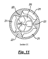
- Figure 20 shows Figure 15 with the addition of longitudinal sections (1124).
- the fluid flow exiting the ESP twists according to the rotational direction of the ESP pump's impellers.
- the fluid flow entering the FFV can also be twisting.
- This twist could be harnessed by longitudinal sections (1124) to cause moving part (1104) to similarly twist.
- the twisting motion can help moving part (1104) to remove solids from second interface (18)/(118) when second interface (18)/(118) is first formed to help second interface (18)/(118) seal.
- Figure 21 shows cross section CC of Figure 20 .
- annulus ports (10)/(110)/(210) and valve discharge ports (11)/(111)/(211) have been shown parallel to the longitudinal axis of the FFV.
- annulus ports (10)/(110)/(210) and valve discharge ports (11)/(111)/(211) can be fashioned into a helix in a direction to match the twist direction of the fluid exiting the ESP to further reduce restrictions to the fluid flow through the FFV. The closer the FFV is to the ESP the more relevant said helix arrangement would be.
- the moving part (4)-(1104) can spring assisted with one end of the spring in contact with moving part (4)-(1104) and with the spring's other end in contact with the internal wall of annulus chamber (15)/(115)/(215).
- housing (1) is shown with a female thread (25) and with a male thread (26) for joining the FFV to the string or to the ESP and string.
- female thread (25) can be where male thread (26) is shown in Figure 1 with male thread (26) where female thread (25) is shown in Figure 1 .
- housing (1) can have a female thread (25) at both ends or a male thread (26) at both ends. Whereby one or both threads can be left hand or right hand or/and be single or multi start. The same equally applies to outer housing (101)/(201).
- shoulder (2) is retained by a thread.
- shoulder (2) can be retained by an interference fit or/and by a circlip in a groove, or by any other commonly known fastening means.
- the FFV can be made from any suitable material that is also suitable for downhole operations.
- cap (119) includes an internal thread (127) to which a draw bar can be fitted to help extract inner housing (108) from outer housing (101) should the FFV need to be disassembled.
- housing (1)/(101)/(201) can be recessed to hold one or more power cable/s to ensure the or each power cable does not slip and cover any of the annulus ports (10)/(110)/(210).
- the outer surface of housing (1)/(101)/(210) can be fashioned to fit a bracket/s or/and clip/s whereby the bracket/s or/and clip/s hold the power cable/s to ensure the or each power cable does to cover any of the annulus ports (10)/(110)/(210).
- Figure 24 shows a variation of Figure 1 where housing (1201) is a two part component joined by thread (1225) as a means of assembling moving part (1204).
- Each component in Figure 24 can be a machined casting or machined from billet. All of the herein previously described variations equally apply to Figure 24 .
- a guide for moving part (1204) can be provided by either the addition of guides (221) from Figure 10 .
- a guide for moving part (1204) can be provided by extending the wall of chamber (1215) into chamber (1214) in the manner of inner housing (108) in Figures 6 and 7 , or/and by extending the wall of chamber (1213) into chamber (1214), whereby said extended wall/s would include ports to provide communication between chambers (1214) and chambers (1213) and (1215).
Landscapes
- Life Sciences & Earth Sciences (AREA)
- Engineering & Computer Science (AREA)
- Geology (AREA)
- Mining & Mineral Resources (AREA)
- Physics & Mathematics (AREA)
- Environmental & Geological Engineering (AREA)
- Fluid Mechanics (AREA)
- General Life Sciences & Earth Sciences (AREA)
- Geochemistry & Mineralogy (AREA)
- Structures Of Non-Positive Displacement Pumps (AREA)
- Infusion, Injection, And Reservoir Apparatuses (AREA)
Applications Claiming Priority (1)
| Application Number | Priority Date | Filing Date | Title |
|---|---|---|---|
| GB1305085.1A GB2515451B (en) | 2013-03-20 | 2013-03-20 | Free flow valve |
Publications (2)
| Publication Number | Publication Date |
|---|---|
| EP2781685A2 true EP2781685A2 (fr) | 2014-09-24 |
| EP2781685A3 EP2781685A3 (fr) | 2014-12-03 |
Family
ID=48226723
Family Applications (1)
| Application Number | Title | Priority Date | Filing Date |
|---|---|---|---|
| EP14165023.4A Withdrawn EP2781685A3 (fr) | 2013-03-20 | 2014-04-16 | Soupape à écoulement libre |
Country Status (3)
| Country | Link |
|---|---|
| US (1) | US20140284061A1 (fr) |
| EP (1) | EP2781685A3 (fr) |
| GB (1) | GB2515451B (fr) |
Cited By (1)
| Publication number | Priority date | Publication date | Assignee | Title |
|---|---|---|---|---|
| CN107420070A (zh) * | 2017-07-21 | 2017-12-01 | 中国海洋石油总公司 | 一种油气井单潜油电泵密闭生产管柱 |
Families Citing this family (2)
| Publication number | Priority date | Publication date | Assignee | Title |
|---|---|---|---|---|
| US10082014B2 (en) | 2016-05-10 | 2018-09-25 | Forum Us, Inc. | Apparatus and method for preventing particle interference of downhole devices |
| DE102017006545A1 (de) * | 2017-07-11 | 2019-01-17 | Wabco Gmbh | Doppelrückschlagventil |
Family Cites Families (13)
| Publication number | Priority date | Publication date | Assignee | Title |
|---|---|---|---|---|
| US4263936A (en) * | 1979-10-09 | 1981-04-28 | Brown Oil Tools, Inc. | Erosion resistant check valve assembly |
| EP0808186A4 (fr) * | 1994-02-14 | 1998-04-15 | Daniel A Summers | Appareil a valve |
| CA2302538C (fr) * | 1999-03-24 | 2005-03-15 | Baker Hughes Incorporated | Robinet de derivation pour tube de production |
| US7717092B2 (en) * | 2006-08-14 | 2010-05-18 | Cummins Filtration Ip Inc. | Fuel system with air venting and fuel anti-drainback |
| GB0802221D0 (en) * | 2008-02-07 | 2008-03-12 | Pump Tools Ltd | Completion tool |
| US8322417B2 (en) * | 2008-03-14 | 2012-12-04 | Schlumberger Technology Corporation | Temperature triggered actuator for subterranean control systems |
| US8281866B2 (en) * | 2009-05-11 | 2012-10-09 | Msi Machineering Solutions Inc. | Production tubing drain valve |
| US9297234B2 (en) * | 2010-04-22 | 2016-03-29 | Packers Plus Energy Services Inc. | Method and apparatus for wellbore control |
| WO2012006457A1 (fr) * | 2010-07-09 | 2012-01-12 | National Oilwell Varco, L.P. | Raccord double de circulation et procédé d'utilisation de ce raccord |
| US9181785B2 (en) * | 2010-11-30 | 2015-11-10 | Baker Hughes Incorporated | Automatic bypass for ESP pump suction deployed in a PBR in tubing |
| US8863849B2 (en) * | 2011-01-14 | 2014-10-21 | Schlumberger Technology Corporation | Electric submersible pumping completion flow diverter system |
| US8739887B2 (en) * | 2012-07-03 | 2014-06-03 | Halliburton Energy Services, Inc. | Check valve for well stimulation |
| EP2929171B1 (fr) * | 2012-12-07 | 2017-02-22 | Volvo Truck Corporation | Mécanisme de soupape pour un moteur à combustion interne, moteur à combustion interne et véhicule automobile |
-
2013
- 2013-03-20 GB GB1305085.1A patent/GB2515451B/en not_active Expired - Fee Related
-
2014
- 2014-04-16 EP EP14165023.4A patent/EP2781685A3/fr not_active Withdrawn
- 2014-04-21 US US14/257,196 patent/US20140284061A1/en not_active Abandoned
Non-Patent Citations (1)
| Title |
|---|
| None |
Cited By (1)
| Publication number | Priority date | Publication date | Assignee | Title |
|---|---|---|---|---|
| CN107420070A (zh) * | 2017-07-21 | 2017-12-01 | 中国海洋石油总公司 | 一种油气井单潜油电泵密闭生产管柱 |
Also Published As
| Publication number | Publication date |
|---|---|
| GB2515451B (en) | 2016-04-20 |
| GB201305085D0 (en) | 2013-05-01 |
| GB2515451A (en) | 2014-12-31 |
| US20140284061A1 (en) | 2014-09-25 |
| EP2781685A3 (fr) | 2014-12-03 |
Similar Documents
| Publication | Publication Date | Title |
|---|---|---|
| CN106246106B (zh) | 一种脉冲式水力射流钻井工具 | |
| US10184314B1 (en) | Downhole valve with cage inserts | |
| US11585186B2 (en) | Standing valve assembly and related systems for downhole reciprocating pump | |
| EA025087B1 (ru) | Клапанная система | |
| US6810955B2 (en) | Gas lift mandrel | |
| US12291939B2 (en) | Electrical actuation of a valve in a wellhead assembly | |
| RU2017136106A (ru) | Буровое долото с самонаправляемым соплом и способ его применения | |
| EP2781685A2 (fr) | Soupape à écoulement libre | |
| RU153634U1 (ru) | Клапан обратный промывочный | |
| EP2203628B1 (fr) | Soupape ouverte par cisaillement | |
| CA2849205A1 (fr) | Vanne a ecoulement libre | |
| US12044230B2 (en) | Methods and kits for assembling a flow cage assembly for downhole reciprocating pump | |
| RU2723792C1 (ru) | Устройство для соединения гидравлических каналов | |
| RU2107805C1 (ru) | Обратный клапан для бурильной колонны | |
| RU2637681C1 (ru) | Трубная головка | |
| US11230893B2 (en) | Method of manufacturing a side pocket mandrel body | |
| RU2455546C1 (ru) | Обратный клапан | |
| US6948917B1 (en) | Valving system for a downhole hydraulically actuated pump | |
| EP3309355A1 (fr) | Système de levage de pompe à jet pour la production de fluides hydrocarbonés | |
| US10597990B2 (en) | Gas lift valve | |
| US20070020114A1 (en) | Jet pump | |
| RU2292439C2 (ru) | Скважинная камера шарифова для съемных клапанов | |
| US11591869B2 (en) | Variable flow diverter downhole tool | |
| RU200706U1 (ru) | Клапан обратный для оборудования колонны-хвостовика | |
| RU2373448C2 (ru) | Клапан обратный |
Legal Events
| Date | Code | Title | Description |
|---|---|---|---|
| PUAI | Public reference made under article 153(3) epc to a published international application that has entered the european phase |
Free format text: ORIGINAL CODE: 0009012 |
|
| 17P | Request for examination filed |
Effective date: 20140416 |
|
| AK | Designated contracting states |
Kind code of ref document: A2 Designated state(s): AL AT BE BG CH CY CZ DE DK EE ES FI FR GB GR HR HU IE IS IT LI LT LU LV MC MK MT NL NO PL PT RO RS SE SI SK SM TR |
|
| AX | Request for extension of the european patent |
Extension state: BA ME |
|
| PUAL | Search report despatched |
Free format text: ORIGINAL CODE: 0009013 |
|
| AK | Designated contracting states |
Kind code of ref document: A3 Designated state(s): AL AT BE BG CH CY CZ DE DK EE ES FI FR GB GR HR HU IE IS IT LI LT LU LV MC MK MT NL NO PL PT RO RS SE SI SK SM TR |
|
| AX | Request for extension of the european patent |
Extension state: BA ME |
|
| RIC1 | Information provided on ipc code assigned before grant |
Ipc: E21B 34/08 20060101AFI20141029BHEP |
|
| R17P | Request for examination filed (corrected) |
Effective date: 20150504 |
|
| RBV | Designated contracting states (corrected) |
Designated state(s): AL AT BE BG CH CY CZ DE DK EE ES FI FR GB GR HR HU IE IS IT LI LT LU LV MC MK MT NL NO PL PT RO RS SE SI SK SM TR |
|
| 17Q | First examination report despatched |
Effective date: 20160915 |
|
| STAA | Information on the status of an ep patent application or granted ep patent |
Free format text: STATUS: THE APPLICATION IS DEEMED TO BE WITHDRAWN |
|
| 18D | Application deemed to be withdrawn |
Effective date: 20170328 |