EP2781744A2 - Radialkolbenhydraulikmaschine und Windturbinengenerator - Google Patents
Radialkolbenhydraulikmaschine und Windturbinengenerator Download PDFInfo
- Publication number
- EP2781744A2 EP2781744A2 EP14160384.5A EP14160384A EP2781744A2 EP 2781744 A2 EP2781744 A2 EP 2781744A2 EP 14160384 A EP14160384 A EP 14160384A EP 2781744 A2 EP2781744 A2 EP 2781744A2
- Authority
- EP
- European Patent Office
- Prior art keywords
- pistons
- roller
- hydraulic machine
- cylinder
- cylinders
- Prior art date
- Legal status (The legal status is an assumption and is not a legal conclusion. Google has not performed a legal analysis and makes no representation as to the accuracy of the status listed.)
- Withdrawn
Links
- 239000003921 oil Substances 0.000 claims description 111
- 239000010687 lubricating oil Substances 0.000 claims description 15
- 238000005461 lubrication Methods 0.000 claims description 12
- 238000004891 communication Methods 0.000 claims description 10
- 230000033001 locomotion Effects 0.000 description 26
- 230000002093 peripheral effect Effects 0.000 description 13
- 230000005540 biological transmission Effects 0.000 description 8
- 238000012423 maintenance Methods 0.000 description 8
- 238000004519 manufacturing process Methods 0.000 description 6
- 230000008859 change Effects 0.000 description 5
- 230000000694 effects Effects 0.000 description 5
- 238000007689 inspection Methods 0.000 description 4
- 230000008901 benefit Effects 0.000 description 3
- 238000005192 partition Methods 0.000 description 3
- 238000003825 pressing Methods 0.000 description 3
- 230000004044 response Effects 0.000 description 3
- 238000013459 approach Methods 0.000 description 2
- 230000015572 biosynthetic process Effects 0.000 description 2
- 238000007599 discharging Methods 0.000 description 2
- 230000000149 penetrating effect Effects 0.000 description 2
- 238000010248 power generation Methods 0.000 description 2
- 230000000452 restraining effect Effects 0.000 description 2
- 230000009471 action Effects 0.000 description 1
- 230000000712 assembly Effects 0.000 description 1
- 238000000429 assembly Methods 0.000 description 1
- 230000004323 axial length Effects 0.000 description 1
- 238000006243 chemical reaction Methods 0.000 description 1
- 239000012141 concentrate Substances 0.000 description 1
- 125000004122 cyclic group Chemical group 0.000 description 1
- 230000007812 deficiency Effects 0.000 description 1
- 238000009826 distribution Methods 0.000 description 1
- 239000012530 fluid Substances 0.000 description 1
- 238000003754 machining Methods 0.000 description 1
- 239000000463 material Substances 0.000 description 1
- 238000000034 method Methods 0.000 description 1
- 230000004048 modification Effects 0.000 description 1
- 238000012986 modification Methods 0.000 description 1
- 230000001360 synchronised effect Effects 0.000 description 1
Images








Classifications
-
- F—MECHANICAL ENGINEERING; LIGHTING; HEATING; WEAPONS; BLASTING
- F04—POSITIVE - DISPLACEMENT MACHINES FOR LIQUIDS; PUMPS FOR LIQUIDS OR ELASTIC FLUIDS
- F04B—POSITIVE-DISPLACEMENT MACHINES FOR LIQUIDS; PUMPS
- F04B1/00—Multi-cylinder machines or pumps characterised by number or arrangement of cylinders
- F04B1/04—Multi-cylinder machines or pumps characterised by number or arrangement of cylinders having cylinders in star- or fan-arrangement
- F04B1/0404—Details or component parts
- F04B1/0413—Cams
- F04B1/0417—Cams consisting of two or more cylindrical elements, e.g. rollers
-
- F—MECHANICAL ENGINEERING; LIGHTING; HEATING; WEAPONS; BLASTING
- F03—MACHINES OR ENGINES FOR LIQUIDS; WIND, SPRING, OR WEIGHT MOTORS; PRODUCING MECHANICAL POWER OR A REACTIVE PROPULSIVE THRUST, NOT OTHERWISE PROVIDED FOR
- F03C—POSITIVE-DISPLACEMENT ENGINES DRIVEN BY LIQUIDS
- F03C1/00—Reciprocating-piston liquid engines
- F03C1/02—Reciprocating-piston liquid engines with multiple-cylinders, characterised by the number or arrangement of cylinders
- F03C1/04—Reciprocating-piston liquid engines with multiple-cylinders, characterised by the number or arrangement of cylinders with cylinders in star or fan arrangement
- F03C1/0403—Details, component parts specially adapted of such engines
- F03C1/0409—Cams
- F03C1/0412—Cams consisting of several cylindrical elements, e.g. rollers
-
- F—MECHANICAL ENGINEERING; LIGHTING; HEATING; WEAPONS; BLASTING
- F03—MACHINES OR ENGINES FOR LIQUIDS; WIND, SPRING, OR WEIGHT MOTORS; PRODUCING MECHANICAL POWER OR A REACTIVE PROPULSIVE THRUST, NOT OTHERWISE PROVIDED FOR
- F03C—POSITIVE-DISPLACEMENT ENGINES DRIVEN BY LIQUIDS
- F03C1/00—Reciprocating-piston liquid engines
- F03C1/02—Reciprocating-piston liquid engines with multiple-cylinders, characterised by the number or arrangement of cylinders
- F03C1/04—Reciprocating-piston liquid engines with multiple-cylinders, characterised by the number or arrangement of cylinders with cylinders in star or fan arrangement
- F03C1/047—Reciprocating-piston liquid engines with multiple-cylinders, characterised by the number or arrangement of cylinders with cylinders in star or fan arrangement the pistons co-operating with an actuated element at the outer ends of the cylinders
- F03C1/0474—Reciprocating-piston liquid engines with multiple-cylinders, characterised by the number or arrangement of cylinders with cylinders in star or fan arrangement the pistons co-operating with an actuated element at the outer ends of the cylinders with two or more radial piston/cylinder units in series
- F03C1/0476—Reciprocating-piston liquid engines with multiple-cylinders, characterised by the number or arrangement of cylinders with cylinders in star or fan arrangement the pistons co-operating with an actuated element at the outer ends of the cylinders with two or more radial piston/cylinder units in series directly located side by side
-
- F—MECHANICAL ENGINEERING; LIGHTING; HEATING; WEAPONS; BLASTING
- F04—POSITIVE - DISPLACEMENT MACHINES FOR LIQUIDS; PUMPS FOR LIQUIDS OR ELASTIC FLUIDS
- F04B—POSITIVE-DISPLACEMENT MACHINES FOR LIQUIDS; PUMPS
- F04B1/00—Multi-cylinder machines or pumps characterised by number or arrangement of cylinders
- F04B1/04—Multi-cylinder machines or pumps characterised by number or arrangement of cylinders having cylinders in star- or fan-arrangement
- F04B1/053—Multi-cylinder machines or pumps characterised by number or arrangement of cylinders having cylinders in star- or fan-arrangement with actuating or actuated elements at the inner ends of the cylinders
- F04B1/0536—Multi-cylinder machines or pumps characterised by number or arrangement of cylinders having cylinders in star- or fan-arrangement with actuating or actuated elements at the inner ends of the cylinders with two or more serially arranged radial piston-cylinder units
- F04B1/0538—Multi-cylinder machines or pumps characterised by number or arrangement of cylinders having cylinders in star- or fan-arrangement with actuating or actuated elements at the inner ends of the cylinders with two or more serially arranged radial piston-cylinder units located side-by-side
Definitions
- the present disclosure relates to a radial piston hydraulic machine which is applicable to a hydraulic pump, a hydraulic motor or the like, as well as a wind turbine generator equipped with the radial piston hydraulic machine.
- a wind turbine generator which converts wind energy into rotational energy of a rotor and further converts the rotational energy into electric power by means of a generator.
- a rated rotation speed of the rotor is relatively small compared to a rated rotation speed of the generator and thus, a mechanical speed increaser (gear type) is provided between the rotor and the generator.
- a wind turbine generator adopting a hydraulic transmission configured by a hydraulic pump and a hydraulic motor, instead of a mechanical speed increaser.
- this type of hydraulic transmission is provided with a hydraulic pump driven by rotation of a rotor, a hydraulic motor coupled to a generator, and a hydraulic pipe for circulating pressurized oil between the hydraulic pump and the hydraulic motor.
- a wind turbine generator configured to transmit rotational energy of a rotor rotated by wind power to a generator via a hydraulic transmission.
- a radial piston hydraulic machine having a plurality of pistons arranged radially.
- a radial piston hydraulic pump used for a power transmission apparatus is disclosed in Patent Document 2.
- This hydraulic pump is provided with an outer race having a cam face on an inner peripheral surface and an inner race having a plurality of cylinders arranged radially to face the outer race.
- the plurality of cylinders of the inner race has a plurality of pistons configured to be slidable therein, and to each of the pistons, a ball is attached so as to contact the cam face.
- Patent Document 3 discloses a radial piston hydraulic machine which serves as a drive train for a wind turbine generator. This radial piston hydraulic machine is provided with a piston which is reciprocable in a cylinder, a roller attached to the piston and a cam having a cam face contacting the roller.
- a radial piston hydraulic machine comprises a rotation shaft, a plurality of cylinders radially arranged around the rotation shaft, a plurality of pistons being reciprocable inside the plurality of cylinders, and a member, such as a cam, for transmitting a motion between the rotation shaft and the piston.
- the hydraulic pump is configured to discharge high pressure operating oil by rotating the rotation shaft using an external force and converting rotational motion of the rotation shaft into reciprocating motion of the piston.
- the hydraulic motor is configured to rotate the rotation shaft using the reciprocating motion of the piston which is supplied with the high pressure operating oil.
- a radial piston hydraulic machine comprises:
- each of the rollers is supported by the pistons at two or more points that are different in the axial direction of the hydraulic machine.
- the conventional single-point supporting method for supporting the roller by the piston at one point there is a room for rotational movement of the roller around the axis of the piston.
- the rotational movement of the roller is suppressed. This effectively suppresses generation of the skew phenomenon of the roller.
- This enables smooth transmission of the power between the cam and the roller.
- by supporting the roller at two or more supporting points in the axial direction it is possible to effectively increase a load carrying capacity of the roller between the supporting points. Thus, even if the length of the roller is increased in the axial direction, it is possible to support the roller reliably.
- the above hydraulic machine is includes a hydraulic pump and a hydraulic motor, and the present invention is applicable to both the hydraulic pump and the hydraulic motor. Further, there are a hydraulic machine which has a rotation part inside the cylinder block and a hydraulic machine which has a rotation part outside the cylinder block.
- the ring cam is an outward ring cam having a cam face facing outward.
- the ring cam is an inward ring cam having a cam face facing inward. The present invention is applicable to both of these.
- the piston is arranged in the cylinder to reciprocate along the radial direction of the hydraulic machine.
- the cam is a ring cam having a plurality of lobes disposed along a circumferential direction of the hydraulic machine, the ring cam being arranged to face the plurality of pistons and being configured rotatable so that the lobes move relative to the plurality of pistons in the circumferential direction, the plurality of cylinders includes a cylinder array that is formed by n cylinders of the plurality of cylinders arranged along the axial direction corresponding to the n pistons, and the plurality of lobes extends linearly in the axial direction over an area in the axial direction occupied by the cylinder array.
- the plurality of lobes extends linearly in the axial direction over the area in the axial direction occupied by the cylinder array. This enables smooth relative rotation of the roller relative to the lobes, the roller corresponding to the n cylinders aligned in the axial direction in the same manner as the plurality of lobes. Further, as the plurality of lobes extends linearly in the axial direction over the area in the axial direction occupied by the cylinder array, it simplifies the configuration of the ring cam and also facilitates work for installing the ring cam. Therefore, it is possible to improve productivity of the radial piston hydraulic machine.
- each of the at least one roller includes a cylindrical part extending along the axial direction over a region where the n pistons are provided, and the cylindrical part is configured to contact the cam over the region in the axial direction.
- the contact area of the roller with respect to the cam face can be increased in the axial direction of the roller, it is possible to reduce a contact surface pressure per unit contact area of the roller with respect to the cam face. Therefore, in these embodiments, it is possible to prevent fatigue fracture of the roller, the ring cam, the pistons and the like, in addition to the skew suppressing effect.
- each of the at least one roller includes at least one contact part configured to contact and engage with the cam and at least one engagement part having a diameter smaller than the at least one contact part and the engagement part being configured to engage with the n pistons.
- each of the at least one roller includes a cylindrical member which is fixed to the n pistons and at least one ring member configured to contact the cam at an outer periphery and to rotate around the cylindrical member, and each of the at least one ring member includes a lubrication part to be supplied with lubricating oil, the lubrication part being provided on an inner periphery of said ring member.
- the cylindrical member is supported by the ring member via an oil film of the lubricating oil.
- This allows, to some extent, for a relative movement of the cylindrical member relative to the ring member (e.g. tilting of the cylindrical member relative to the ring member, where the axis of the cylindrical member tilts relative to the axis of the ring member).
- this difference in size and dimension can be absorbed by the relative movement between the ring member and the cylindrical member so that the n pistons can be reciprocated smoothly in the n cylinders.
- a supply line is provided for supplying operating oil of a hydraulic chamber formed by the piston and the cylinder as the lubricating oil to the lubrication part.
- the supply line for supplying the lubricating oil to the lubrication part can be formed in the piston and in the cylindrical part, instead of outside the cylinder. As a result, it is possible to attain the above effect of smooth reciprocating of the n pistons in the n cylinders, with a simple configuration.
- Each of the aforesaid n pistons has a piston circumferential surface which is crowned so that an outer diameter of an end of the piston in an axial direction of the piston is smaller than an outer diameter of a center of the piston in the axial direction.
- an oil supply valve is also provided to collectively change a supply state of operating oil to n hydraulic chambers formed by the n pistons and n cylinders of the plurality of cylinders corresponding to the n pistons, respectively.
- the cylinder block comprises: a cylinder cartridge having at least one cylinder of n cylinders of the plurality of cylinders corresponding to the n pistons; a cylinder block body having a cartridge hole into which the cylinder cartridge is inserted, and the hydraulic machine further comprises a cover member attached to the cylinder block body so as to restrict the cylinder cartridge inserted in the cartridge hole, so to prevent it from coming out from the cylinder block body along the radial direction.
- the cylinder block comprises: a cylinder cartridge having n cylinders of the plurality of cylinders corresponding to the n pistons; and a cylinder block body having a cartridge hole into which the cylinder cartridge is inserted, and the cylinder cartridge is configured to be removable from and insertable into the cylinder block body in such a state that the n pistons are integrated with the roller corresponding to the n pistons.
- roller or the n pistons need to be replaced due to influence of the frictional wear or the like, the roller and the n pistons can be replaced in a unitized state. This reduces workload for replacing the parts and also facilitates maintenance of the hydraulic machine.
- the cylinder cartridge is configured removable from the cylinder block body to an opposite side of the cam in a radial direction of the hydraulic machine in such a state that the cylinder cartridge is integrated with a valve for controlling a state of communication between a hydraulic chamber formed by the piston and the cylinder and an outside of the hydraulic chamber.
- the valve is replaced in the state where the cylinder cartridge is integrated with the valve. This reduces workload for replacing the valve and also facilitates maintenance of the hydraulic machine. Further, the cylinder cartridge can be removed without removing the cam from the hydraulic machine and without causing interference between the cylinder cartridge and the cam. This further facilitates the replacement work of the cylinder cartridge.
- the cylinder block is configured to be separable into a plurality of segments each of which includes n cylinders of the plurality of cylinders corresponding to the n pistons.
- cylinder block which is separable per each of the segments which includes n cylinders associated with one roller that is shared by n pistons as described above, one roller, n pistons and one segment of the cylinder block holding the roller and the n pistons can be integrally removed and attached at the replacement thereof. Therefore, this facilitates assembling and disassembling of the cylinder block including the rollers, the pistons and the cylinders. This also facilitates maintenance and inspection of the roller, the piston and the like.
- the cylinder block body is formed in a continuous manner over an entire circumference in a circumferential direction of the hydraulic machine.
- the hydraulic machine constitutes a hydraulic machine for a drive train of a wind turbine generator
- the wind load acts on the cylinder block to some extent.
- the positions of remaining segments are slightly displaced. This makes it difficult to mount a new segment.
- by forming the cylinder block body in a continuous manner over the entire circumference in the circumferential direction of the hydraulic machine it is possible to solve problems resulting from assembling of the segments.
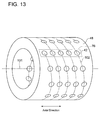
- the plurality of cylinders is provided on a moving path of n cylinders of the plurality of cylinders corresponding to the n pistons when the n cylinders are (virtually) moved in a spiral or spiral-like manner around an axis of the hydraulic machine.
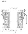
- FIG.2 is a longitudinal section of a hydraulic machine according to one embodiment.
- a hydraulic machine 40 illustrated in FIG.2 configures the hydraulic pump 22 or the hydraulic motor 28.
- the hydraulic machine 40 comprises a plurality of cylinders 42 formed along the radial direction of the hydraulic machine 40, a plurality of pistons provided slidably in the plurality of cylinders 42, respectively, and a cylinder block in which the plurality of cylinders 42 is provided.
- the cylinders 42 are disposed at equal intervals in the circumferential direction and axial direction (arrow a) of the cylinder block 48.
- Each of the pistons 44 is configured to reciprocate in the cylinder 42 along the radial direction of the hydraulic machine 40. In response to the reciprocating motion of each of the piston 44, volume of a hydraulic chamber r formed by the piston 44 and the cylinder 42 changes cyclically.
- the cylinder block 48 As some of the functions that the cylinder block 48 is expected to serve, there are the function of forming the cylinder 24 as the slide part for guiding the piston 44 slidably and the function of forming a structure for supporting the cylinder 42.
- the cylinder sleeve 64 and the cylinder block body 66 can share the functions expected in the cylinder block 48 (formation of the cylinder 42 and formation of the structure). This enables designing of the cylinder sleeve 64 and the cylinder block body 66 according to their respective functions, hence achieving reduced weight of the cylinder block 48 as a whole.
- an operating oil space s2 is formed.
- the hydraulic pressure acting on the valve element 99 via the operating oil space s2 exceeds the pressing force of the spring 100, the spring type on-off valve is released and hence the operating oil space s2 communicates with the high-pressure oil discharge pipe 96.
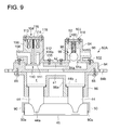
- the casing 94 for the high-pressure valve block 92 and the casing 106 for the low-pressure valve block 104 are configured such that a top cover 103 belonging to the casing 94 and a top cover 116 belonging to the casing 106 are formed separately from the casing body and mounted on the casing body by fastening embers (e.g. bolts) 118.
- fastening embers e.g. bolts
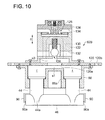
- the projection 148 is inserted in the small diameter section 142 to prevent the axial movement of the roller 46.
- the restraining arm 90 illustrated in FIG.9 in the piston 44 Therefore, it is not necessary to adapt the axial direction dimension of the roller 46 to the restraining arm 90. This enhances the degree of freedom in designing the roller 46.
- a supply line 156 is formed to supply the operating oil as lubricating oil to the lubrication part from the hydraulic chamber r formed by the piston 44 and the cylinder 42.
- the supply line 156 for supplying the lubricating oil to the lubrication part 154 can be formed in the piston 44 and in the cylindrical part 150 instead of outside the cylinder 42. As a result, it is possible to achieve smooth rotation of the ring member 152 relative to the cylindrical member 150 with a simple configuration.
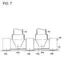
- the distance between two pistons 44 in the axial direction of the roller 46 is 6x, whereas the distance between a supporting point of the piston 44 and the edge of the roller 46 is x.
- the following relationship is satisfied, (the distance between the support areas of the pistons 44 in the axial direction of the roller 46) > (a distance twice as large as the distance between the edge of the roller 46 and the support area of the piston 44).
- the pistons 44 are configured so that a load at a position which is 3x apart from the support area of the piston 44 supporting the roller 46 toward the roller center in the axial direction of the roller 46 equals to a load at a position which is x apart from the support area toward the outside in the axial direction.
Landscapes
- Engineering & Computer Science (AREA)
- Mechanical Engineering (AREA)
- General Engineering & Computer Science (AREA)
- Chemical & Material Sciences (AREA)
- Combustion & Propulsion (AREA)
- Reciprocating Pumps (AREA)
- Hydraulic Motors (AREA)
- Wind Motors (AREA)
Applications Claiming Priority (2)
| Application Number | Priority Date | Filing Date | Title |
|---|---|---|---|
| JP2013055062A JP2014181578A (ja) | 2013-03-18 | 2013-03-18 | ラジアルピストン式油圧機械および風力発電装置 |
| JP2013267219A JP2015124609A (ja) | 2013-12-25 | 2013-12-25 | ラジアルピストン式油圧機械及び風力発電装置 |
Publications (2)
| Publication Number | Publication Date |
|---|---|
| EP2781744A2 true EP2781744A2 (de) | 2014-09-24 |
| EP2781744A3 EP2781744A3 (de) | 2014-10-29 |
Family
ID=50289488
Family Applications (1)
| Application Number | Title | Priority Date | Filing Date |
|---|---|---|---|
| EP14160384.5A Withdrawn EP2781744A3 (de) | 2013-03-18 | 2014-03-17 | Radialkolbenhydraulikmaschine und Windturbinengenerator |
Country Status (1)
| Country | Link |
|---|---|
| EP (1) | EP2781744A3 (de) |
Citations (3)
| Publication number | Priority date | Publication date | Assignee | Title |
|---|---|---|---|---|
| JP2010019192A (ja) | 2008-07-11 | 2010-01-28 | Toyota Motor Corp | ピストンポンプ及びそれを備えた動力伝達装置、並びにピストンモータ |
| US20100040470A1 (en) | 2008-08-13 | 2010-02-18 | Jacob Johannes Nies | Wind energy system with fluid-working machine with non-symmetric actuation |
| WO2010033035A1 (en) | 2008-09-17 | 2010-03-25 | Chapdrive As | Turbine speed stabilisation control system |
Family Cites Families (1)
| Publication number | Priority date | Publication date | Assignee | Title |
|---|---|---|---|---|
| GB1085338A (en) * | 1965-07-02 | 1967-09-27 | Cessna Aircraft Co | Improvements in and relating to hydraulic reciprocating motors |
-
2014
- 2014-03-17 EP EP14160384.5A patent/EP2781744A3/de not_active Withdrawn
Patent Citations (3)
| Publication number | Priority date | Publication date | Assignee | Title |
|---|---|---|---|---|
| JP2010019192A (ja) | 2008-07-11 | 2010-01-28 | Toyota Motor Corp | ピストンポンプ及びそれを備えた動力伝達装置、並びにピストンモータ |
| US20100040470A1 (en) | 2008-08-13 | 2010-02-18 | Jacob Johannes Nies | Wind energy system with fluid-working machine with non-symmetric actuation |
| WO2010033035A1 (en) | 2008-09-17 | 2010-03-25 | Chapdrive As | Turbine speed stabilisation control system |
Also Published As
| Publication number | Publication date |
|---|---|
| EP2781744A3 (de) | 2014-10-29 |
Similar Documents
| Publication | Publication Date | Title |
|---|---|---|
| US8358024B2 (en) | Wind turbine generator and tidal current generator with a hydraulic transmission | |
| EP2766601B1 (de) | Windenergieanlage | |
| EP3104006B1 (de) | Hydraulische maschine und vorrichtung zur erzeugung von strom aus erneuerbarer energie | |
| EP2781744A2 (de) | Radialkolbenhydraulikmaschine und Windturbinengenerator | |
| BR112013032575B1 (pt) | bomba hidráulica de fundo de poço | |
| EP2726737B1 (de) | Hydraulischer motor oder pumpe und windturbinengenerator | |
| EP2770203B1 (de) | Radialkolbenfluidmaschine und Stromerzeugungsvorrichtung des Typs erneuerbarer Energien | |
| JP2014129775A (ja) | ラジアルピストン式油圧機械および風力発電装置 | |
| EP2770204A1 (de) | Hydraulischer Motor, Verfahren zum Starten eines hydraulischen Motors und und Stromerzeugungsvorrichtung des Typs erneuerbarer Energien | |
| JP2015124609A (ja) | ラジアルピストン式油圧機械及び風力発電装置 | |
| EP3141748B1 (de) | Hydraulische maschine vom radialkolbentyp und windturbinenstromerzeugungsvorrichtung | |
| EP2739846B1 (de) | Flüssigkeitsarbeitsmaschine und windturbinengenerator | |
| US20040255773A1 (en) | Rotary radial piston machine | |
| EP2770201B1 (de) | Ventilzylinderschnittstelle, Anordnungsverfahren für Ventilzylinderschnittstelle und Stromerzeugungsvorrichtung des Typs erneuerbare Energien | |
| EP2896825B1 (de) | Vorrichtung zur stromerzeugung mithilfe erneuerbarer energien | |
| EP2749768B1 (de) | Radialkolbenhydraulikmaschine und Windturbinengenerator | |
| JP2014181578A (ja) | ラジアルピストン式油圧機械および風力発電装置 | |
| JP2023532674A (ja) | 多段コンプレッサ | |
| EP2749769A1 (de) | Radialkolbenhydraulikmaschine und Windturbinengenerator | |
| JP6363148B2 (ja) | 再生可能エネルギー型発電装置 | |
| JP2014129770A (ja) | ラジアルピストン式油圧機械、その組立て方法及び風力発電装置 | |
| EP2770202B1 (de) | Steuerventil, Montageverfahren für Steuerventil und Stromerzeugungsvorrichtung des Typs erneuerbarer Energien | |
| JP2014129772A (ja) | ラジアルピストン式油圧機械および風力発電装置 | |
| JP2014129782A (ja) | ラジアルピストン式油圧機械および風力発電装置 | |
| JP2015124608A (ja) | ラジアルピストン式油圧機械および風力発電装置 |
Legal Events
| Date | Code | Title | Description |
|---|---|---|---|
| PUAI | Public reference made under article 153(3) epc to a published international application that has entered the european phase |
Free format text: ORIGINAL CODE: 0009012 |
|
| 17P | Request for examination filed |
Effective date: 20140317 |
|
| AK | Designated contracting states |
Kind code of ref document: A2 Designated state(s): AL AT BE BG CH CY CZ DE DK EE ES FI FR GB GR HR HU IE IS IT LI LT LU LV MC MK MT NL NO PL PT RO RS SE SI SK SM TR |
|
| AX | Request for extension of the european patent |
Extension state: BA ME |
|
| PUAL | Search report despatched |
Free format text: ORIGINAL CODE: 0009013 |
|
| AK | Designated contracting states |
Kind code of ref document: A3 Designated state(s): AL AT BE BG CH CY CZ DE DK EE ES FI FR GB GR HR HU IE IS IT LI LT LU LV MC MK MT NL NO PL PT RO RS SE SI SK SM TR |
|
| AX | Request for extension of the european patent |
Extension state: BA ME |
|
| RIC1 | Information provided on ipc code assigned before grant |
Ipc: F04B 1/04 20060101AFI20140924BHEP Ipc: F03C 1/047 20060101ALI20140924BHEP Ipc: F03C 1/30 20060101ALI20140924BHEP Ipc: F04B 1/053 20060101ALI20140924BHEP |
|
| STAA | Information on the status of an ep patent application or granted ep patent |
Free format text: STATUS: THE APPLICATION IS DEEMED TO BE WITHDRAWN |
|
| 18D | Application deemed to be withdrawn |
Effective date: 20150430 |