EP2782191B1 - Polarisationsvorrichtung für ein mikrowellenübertragungssystem im freien - Google Patents
Polarisationsvorrichtung für ein mikrowellenübertragungssystem im freien Download PDFInfo
- Publication number
- EP2782191B1 EP2782191B1 EP12861752.9A EP12861752A EP2782191B1 EP 2782191 B1 EP2782191 B1 EP 2782191B1 EP 12861752 A EP12861752 A EP 12861752A EP 2782191 B1 EP2782191 B1 EP 2782191B1
- Authority
- EP
- European Patent Office
- Prior art keywords
- polarization component
- waveguide
- polarization
- degrees
- component
- Prior art date
- Legal status (The legal status is an assumption and is not a legal conclusion. Google has not performed a legal analysis and makes no representation as to the accuracy of the status listed.)
- Active
Links
- 230000010287 polarization Effects 0.000 title claims description 297
- 230000005540 biological transmission Effects 0.000 title claims description 24
- 238000007789 sealing Methods 0.000 claims description 9
- 238000010586 diagram Methods 0.000 description 4
- 230000005684 electric field Effects 0.000 description 3
- 239000000463 material Substances 0.000 description 2
- 229910000838 Al alloy Inorganic materials 0.000 description 1
- 239000000956 alloy Substances 0.000 description 1
- 230000000694 effects Effects 0.000 description 1
- PCHJSUWPFVWCPO-UHFFFAOYSA-N gold Chemical compound [Au] PCHJSUWPFVWCPO-UHFFFAOYSA-N 0.000 description 1
- 229910052737 gold Inorganic materials 0.000 description 1
- 239000010931 gold Substances 0.000 description 1
- 229910052751 metal Inorganic materials 0.000 description 1
- 239000002184 metal Substances 0.000 description 1
- 229920002379 silicone rubber Polymers 0.000 description 1
- 229910052709 silver Inorganic materials 0.000 description 1
- 239000004332 silver Substances 0.000 description 1
- 238000001228 spectrum Methods 0.000 description 1
Images


Classifications
-
- H—ELECTRICITY
- H01—ELECTRIC ELEMENTS
- H01Q—ANTENNAS, i.e. RADIO AERIALS
- H01Q15/00—Devices for reflection, refraction, diffraction or polarisation of waves radiated from an antenna, e.g. quasi-optical devices
- H01Q15/24—Polarising devices; Polarisation filters
- H01Q15/242—Polarisation converters
- H01Q15/246—Polarisation converters rotating the plane of polarisation of a linear polarised wave
-
- H—ELECTRICITY
- H01—ELECTRIC ELEMENTS
- H01P—WAVEGUIDES; RESONATORS, LINES, OR OTHER DEVICES OF THE WAVEGUIDE TYPE
- H01P1/00—Auxiliary devices
- H01P1/165—Auxiliary devices for rotating the plane of polarisation
Definitions
- Embodiments of the present invention relate to the field of microwave communications, and in particular, to a polarization device used for a microwave outdoor transmission system.
- a microwave outdoor transmission system will use two manners, vertical polarization and horizontal polarization, to transmit a signal. Therefore, a polarization manner of an outdoor active device in the microwave outdoor transmission system needs to be compatible with the two polarization manners, horizontal polarization and vertical polarization.
- a polarization scheme supporting the two polarization manners is implemented by using two polarization components. That is, one polarization component supports horizontal polarization, the other polarization component supports vertical polarization, and switching between the two polarization manners is implemented by replacing the two components.
- an input end of a polarization component is a horizontal polarization direction
- an electric field direction of an output end is horizontal polarization or vertical polarization.
- one polarization component is assembled in an antenna system, and the other polarization component is stored in an auxiliary material package. A risk of losing a polarization component may occur during an onsite operation.
- a polarization component needs to be replaced on site to change a polarization manner, causing operation complexity.
- another polarization scheme supporting the two polarization manners is implemented by using a specially-made dedicated polarization component.
- an electric field of an input end of the polarization component is a 45-degree direction
- an electric field direction of an output end of the polarization component is horizontal polarization or vertical polarization.
- the specially-made dedicated polarization component needs to be installed at an antenna end. Due to particularity of the polarization component, the entire antenna end needs to be replaced, so as to install the polarization component.
- replacing the antenna end is not convenient and involves a high replacement cost. Therefore, this polarization scheme cannot be compatible with the existing antenna end.
- a polarization device which supports the two polarization manners, can conveniently switch between the two polarization manners, and is compatible with an existing antenna.
- GB 2012116A describes compensating the point of discontinuity between two axially-aligned adjoining rectangular waveguides which are rotationally offset about their common axis.
- the compensation is effected by a plate arranged between the waveguides which plate has an aperture therethrough which corresponds substantially to the common adjoining cross-section of the waveguides but has two projections which extend symmetrically of the bisector of an angle formed between the shorter cross-sectional axes of the waveguides.
- Embodiments of the present invention provide a polarization device used for a microwave outdoor transmission system.
- a polarization device used for a microwave outdoor transmission system includes an antenna and an outdoor active device.
- the polarization device includes:
- a microwave outdoor transmission unit includes the polarization device according to an embodiment of the present invention.
- the communications system includes the microwave outdoor transmission unit according to an embodiment of the present invention.
- the polarization device can be compatible with an existing antenna, thereby saving a cost of replacing the existing antenna.
- FIG. 1 is an assembly diagram of a polarization device 10 according to an embodiment of the present invention, where the polarization device 10 is used for a microwave outdoor transmission system.
- the microwave outdoor transmission system includes an antenna (not shown in the figure) and an outdoor active device 100.
- the outdoor active device is usually a microwave outdoor module, which includes a power supply, an intermediate frequency active transceiving link, a radio frequency (including a microwave frequency band) active transceiving link, a duplexer, and an auxiliary structural part.
- a waveguide of the outdoor active device 100 of the microwave outdoor transmission system is at an included angle of 45 degrees with a waveguide of the antenna. As shown in FIG.
- the polarization device 10 mainly includes a first polarization component 200 and a second polarization component 300.
- the first polarization component 200 is fixed, in a removable manner, onto the outdoor active device 100 of the microwave outdoor transmission system, so that a waveguide of the first polarization component 200 keeps staying in a same direction with a waveguide of the outdoor active device 100.
- the second polarization component 300 is fixed, in a removable manner, onto the first polarization component 200, so as to allow an included angle between the waveguide of the first polarization component 200 and a waveguide of the second polarization component 300 to be adjusted through rotation of the second polarization component 300 in relation to the first polarization component 200.
- the waveguide of the antenna and the waveguide of the outdoor active device may be arranged into a rectangular waveguide port, so as to facilitate radio wave transmitting.
- the waveguide of the first polarization component 200 and the waveguide of the second polarization component 300 are also preferentially arranged into a rectangular waveguide port, and their shapes and sizes correspond to those of the waveguide of the antenna and the waveguide of the outdoor active device 100.
- FIG. 2 shows a perspective view of the first polarization component 200 according to an embodiment of the present invention.
- the first polarization component 200 is basically a cylindrical pipe 210, where the cylindrical pipe has a closed end 220 and an open end 230. Therefore, the first polarization component 200 is basically in a cup shape.
- a waveguide 240 of the first polarization component 200 is arranged in a center of the closed end 220 of the cylindrical pipe 210, that is, arranged in a center of a bottom of the cup-shaped component.
- the waveguide 240 may be arranged into a rectangular waveguide port, and its shape corresponds to that of a waveguide of the outdoor active device 100.
- the closed end 220 of the cylindrical pipe 210 has a flange part 250.
- the first polarization component 200 is fixed, by using a fastener (not shown in the figure), onto the outdoor active device 100 through a fastener hole (not shown in the figure) on the flange part 250.
- a fastener not shown in the figure
- a person skilled in the art may understand that there may be multiple fastener holes on the flange part 250, and preferentially they are distributed evenly around the flange part 250.
- a bolt may be selected as the fastener for fixing the first polarization component 200 onto the outdoor active device. In this case, a corresponding thread hole is arranged on the outdoor active device, so as to accept the fastener.
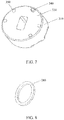
- FIG. 3 shows a perspective view of the second polarization component 300 according to an embodiment of the present invention. What is shown in FIG. 3 is a preferential scheme of the second polarization component 300.
- the second polarization component 300 is basically a cylinder 310, and has a first end surface 320 and a second end surface 330 (see FIG. 7 ).
- An outer diameter of the cylinder 310 basically mates with an inner diameter of the cylindrical pipe 210 of the first polarization component 200 shown in FIG. 2 , so that the cylinder 310 can be inserted into the cylindrical pipe 210 to implement assembly of the first polarization component 200 and the second polarization component 300.
- the second end surface 330 of the cylinder 310 faces an inner side of the closed end 220 of the cylindrical pipe 210.
- a waveguide 340 of the second polarization component 300 is in a form of a rectangular waveguide port, threads through the first end surface 320 and the second end surface 330 of the cylinder 310, and is arranged in a center of the first end surface 320.
- a shape and a size of the waveguide 340 correspond to those of the waveguide 240 of the first polarization component 200.
- the second polarization component 300 When the second polarization component 300 cooperates with the first polarization component 200, the second polarization component 300 can be rotated in relation to the first polarization component 200 to adjust an included angle between the waveguide 340 of the second polarization component 300 and the waveguide 240 of the first polarization component 200, so as to implement switching between horizontal polarization and vertical polarization of an antenna.
- an included angle between the waveguides refers to an included angle between longitudinal axes of rectangles of various waveguides, and it is the same below.
- the second polarization component 300 is fixed, by using a fastener, onto the first polarization component 200 through a passing-through fastener hole 350 that is arranged around the cylinder 310.
- a person skilled in the art may understand that there may be multiple fastener holes 350 on the cylinder 310, and preferentially they are distributed evenly around the cylinder.
- a bolt may be selected as the fastener for fixing the second polarization component 300 onto the first polarization component 200.
- a corresponding thread hole 290 (see FIG. 2 ) is arranged at the closed end 220 of the first polarization component 200, so as to accept the fastener.
- FIG. 4 shows relative location relationships between waveguide ports of various components when horizontal polarization is implemented on the antenna by using the first polarization component 200 and the second polarization component 300.
- the figure is simplified and only the waveguide ports of the components are shown.
- FIG. 4 shows a top view of the waveguide ports stacked together when the antenna, the outdoor active device, the first polarization component 200, and the second polarization component 300 are installed together.
- Two-dot dashed lines indicate the waveguide of the antenna during horizontal polarization
- single-dot dashed lines indicate the waveguide of the outdoor active device 100 and the waveguide 240 of the first polarization component 200
- real lines indicate the waveguide 340 of the second polarization component 300, where the waveguide of the outdoor active device 100 and the waveguide 240 of the first polarization component 200 are kept in a same direction.
- an azimuth of the waveguide of the antenna is 0 degrees
- azimuths of the waveguide 240 of the first polarization component 200 and the waveguide of the outdoor active device are 45 degrees.
- included angles between the two and the waveguide of the antenna separately are 45 degrees.
- An azimuth of the waveguide 340 of the second polarization component 300 is 22.5 degrees. That is, an included angle between the waveguide 340 of the second polarization component 300 and the waveguide 240 of the first polarization component 200 is 22.5 degrees. In this way, the horizontal polarization of the antenna is implemented with the configuration.
- FIG. 5 shows the relative location relationships between the waveguide ports of various components when vertical polarization is implemented on the antenna by using the first polarization component 200 and the second polarization component 300. Likewise, for clear exemplary description, the figure is simplified and only the waveguide ports of the components are shown.
- FIG. 5 shows a top view of the waveguide ports stacked together when the antenna, the outdoor active device, the first polarization component 200, and the second polarization component 300 are installed together.
- Two-dot dashed lines indicate the waveguide of the antenna during vertical polarization
- single-dot dashed lines indicate the waveguide of the outdoor active device 100 and the waveguide 240 of the first polarization component 200
- real lines indicate the waveguide 340 of the second polarization component 300, where the waveguide of the outdoor active device 100 and the waveguide 240 of the first polarization component 200 are kept in a same direction.
- the azimuth of the waveguide of the antenna is 90 degrees
- the azimuths of the waveguide 240 of the first polarization component 200 and the waveguide of the outdoor active device 100 are 45 degrees.
- an included angle between the waveguide 240 of the first polarization component 200 and the waveguide of the antenna is 45 degrees
- an included angle between the waveguide of the outdoor active device 100 and the waveguide of the antenna is 45 degrees
- the azimuth of the waveguide 340 of the second polarization component 300 is 67.5 degrees. That is, the included angle between the waveguide 340 of the second polarization component 300 and the waveguide 240 of the first polarization component 200 is 22.5 degrees. In this way, the vertical polarization of the antenna is implemented with the configuration.
- the waveguide 240 of the first polarization component 200 is always installed at an angle of 45 degrees, whereas the included angle between the waveguide 340 of the second polarization component 300 and the waveguide 240 of the first polarization component 200 is 22.5 degrees but the two waveguides face different directions. If it is considered in FIG. 4 that the included angle between the waveguide 340 of the second polarization component 300 and the waveguide 240 of the first polarization component 200 is -22.5 degrees, it can be considered that in FIG. 5 , the included angle between the waveguide 340 of the second polarization component 300 and the waveguide 240 of the first polarization component 200 is 22.5 degrees. Therefore, flexible switching between the horizontal polarization and the vertical polarization of the antenna can be implemented by adjusting an angle of rotation of the second polarization component 300 in relation to the first polarization component 200.
- the present invention is not limited to the switching between the horizontal polarization and the vertical polarization of the antenna.
- a person skilled in the art understands that any polarization angle of the antenna may also be implemented through the relative rotation between the second polarization component 300 and the first polarization component 200.
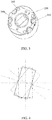
- FIG. 6 is an exemplary structure of the first polarization component 200 according to an embodiment of the present invention.
- the inner side of the closed end 220 of the cylindrical pipe 210 of the first polarization component 200 includes an arc groove 260, where the arc groove 260 extends along a circumferential direction of the cylindrical pipe 210, and its span is 45 degrees.
- the arc groove 260 has a first end 262 and a second end 264, so as to cooperate with a corresponding bulge (described below) on the second polarization component 300, thereby implementing the horizontal polarization and the vertical polarization of the antenna.
- FIG. 1 is an exemplary structure of the first polarization component 200 according to an embodiment of the present invention.
- the inner side of the closed end 220 of the cylindrical pipe 210 of the first polarization component 200 includes an arc groove 260, where the arc groove 260 extends along a circumferential direction of the cylindrical pipe 210, and its span is 45 degrees.
- the arc groove 260 has
- the second end surface 330 of the cylinder 310 of the second polarization component 300 includes a bulge 340 arranged on a surrounding edge.
- the bulge 340 cooperates inside the arc groove 360.
- a position of the arc groove 260 at the closed end 220 and/or a position of the bulge 340 on the second end surface 330 may be selected, so that the horizontal polarization of the antenna is implemented when the bulge 340 is located at the first end 262 of the arc groove 260, whereas the vertical polarization of the antenna is implemented when the bulge 340 is located at the second end 264 of the arc groove 260.
- the fastener hole 350 on the second polarization component 300 shown in FIG. 7 may be arranged into an arc hole, where the fastener hole 350 is used to fix the second polarization component 300 onto the first polarization component 200, and a span of the arc hole corresponds to the span of the arc groove 260.
- the second polarization component 300 does not need to be taken out of the first polarization component 200. Instead, what is only required is to loosen the fastener, rotate the second polarization component 300, and tighten the fastener after an expected position is reached.
- the number of arc holes is at least one, so as to provide a more reliable fixing effect.
- the span of the arc groove 260 is not limited to 45 degrees. A greater or smaller span may be selected according to a specific application requirement, so as to implement polarization of different angles. According to an exemplary embodiment, the span of the arc groove 260 is at least 45 degrees. In an embodiment in which the fastener hole 350 on the second polarization component 300 is an arc hole, the span of the arc hole is correspondingly at least 45 degrees.
- annular groove 270 is arranged on a communications ground between the waveguide 240 and the cylindrical pipe 210.
- a sealing ring 280 (shown in FIG. 8 ) may be arranged in the annular groove 270, so that the sealing ring 280 provides a waterproof sealing function when the second polarization component 300 cooperates with the first polarization component 200.
- a silicon rubber material may be chosen for the sealing ring 280, so as to ensure electrical transmission performance while providing waterproof sealing.
- the first polarization component 200 and the second polarization component 300 may be made of an aluminum alloy material.
- Metal, such as gold or silver, may be electroplated on surfaces of the waveguide 240 of the first polarization component 200 and the waveguide 340 of the second polarization component 300, so as to further improve polarization efficiency.
- the polarization device can be compatible with an existing antenna and implement reconstruction of the existing antenna, thereby saving a cost of replacing the existing antenna.
- a microwave outdoor transmission unit may include the polarization device 10, and is configured to implement microwave horizontal polarization and/or vertical polarization.
- a communications system includes the microwave outdoor transmission unit, where the microwave outdoor transmission unit utilizes an included polarization device 10 to implement microwave horizontal polarization and/or vertical polarization.
Landscapes
- Variable-Direction Aerials And Aerial Arrays (AREA)
Claims (10)
- Polarisationseinrichtung (10), die für ein im Freien befindliches Mikrowellenübertragungssystem verwendet wird, wobei das im Freien befindliche Mikrowellenübertragungssystem eine Antenne und eine im Freien befindliche aktive Einrichtung (100) umfasst und die Polarisationseinrichtung (10) Folgendes umfasst:eine erste Polarisationskomponente (200), wobei die erste Polarisationskomponente (200) auf entfernbare Weise an der im Freien befindlichen aktiven Einrichtung (100) festgemacht ist, so dass ein Wellenleiter (240) der ersten Polarisationskomponente (200) stets in einer gleichen Richtung mit einem Wellenleiter der im Freien befindlichen aktiven Einrichtung (100) bleibt; undeine zweite Polarisationskomponente (300), wobei die zweite Polarisationskomponente (300) auf entfernbare Weise an der ersten Polarisationskomponente (200) festgemacht ist, so dass ein eingeschlossener Winkel zwischen einem Wellenleiter der zweiten Polarisationskomponente (300) und dem Wellenleiter (240) der ersten Polarisationskomponente (200) durch Drehung der zweiten Polarisationskomponente (300) in Bezug auf die erste Polarisationskomponente (200) verstellt werden kann;wobei die Polarisationseinrichtung für horizontale Polarisation konfiguriert ist, wenn ein Azimut eines Wellenleiters der Antenne 0 Grad beträgt und ein Azimut des Wellenleiters der ersten Polarisationskomponente 45 Grad beträgt, wobei ein eingeschlossener Winkel zwischen dem Wellenleiter der Antenne und dem Wellenleiter der ersten Polarisationskomponente 45 Grad beträgt und ein Azimut des Wellenleiters der im Freien befindlichen aktiven Einrichtung 45 Grad beträgt, wobei ein eingeschlossener Winkel zwischen dem Wellenleiter der Antenne und dem Wellenleiter der im Freien befindlichen aktiven Einrichtung 45 Grad beträgt und ein Azimut des Wellenleiters der zweiten Polarisationskomponente 22,5 Grad beträgt, wobei ein eingeschlossener Winkel zwischen dem Wellenleiter der zweiten Polarisationskomponente und dem Wellenleiter der ersten Polarisationskomponente 22,5 Grad beträgt; undwobei die Polarisationseinrichtung für vertikale Polarisation konfiguriert ist, wenn der Azimut des Wellenleiters der Antenne 90 Grad beträgt und der Azimut des Wellenleiters der ersten Polarisationskomponente 45 Grad beträgt, wobei ein eingeschlossener Winkel zwischen dem Wellenleiter der ersten Polarisationskomponente und dem Wellenleiter der Antenne 45 Grad beträgt, und der Azimut des Wellenleiters der im Freien befindlichen aktiven Einrichtung 45 Grad beträgt, wobei ein eingeschlossener Winkel zwischen dem Wellenleiter der im Freien befindlichen aktiven Einrichtung und dem Wellenleiter der Antenne 45 Grad beträgt, und der Azimut des Wellenleiters der zweiten Polarisationskomponente 67,5 Grad beträgt, wobei ein eingeschlossener Winkel zwischen dem Wellenleiter der zweiten Polarisationskomponente und dem Wellenleiter der ersten Polarisationskomponente 22,5 Grad beträgt.
- Polarisationseinrichtung (10) nach Anspruch 1, wobei:die erste Polarisationskomponente (200) ein zylindrisches Rohr (210) umfasst, das zylindrische Rohr (210) ein geschlossenes Ende (220) und ein offenes Ende (230) aufweist, der Wellenleiter (240) der ersten Polarisationskomponente (200) in einer Mitte des geschlossenen Endes (220) des zylindrischen Rohrs (210) angeordnet ist, das geschlossene Ende (220) des zylindrischen Rohrs (210) ein Flanschteil (250) aufweist, und die erste Polarisationskomponente (200) mittels eines Befestigungsmittels an der im Freien befindlichen aktiven Einrichtung (100) durch ein Befestigungsloch an dem Flanschteil (250) hindurch festgemacht ist; unddie zweite Polarisationskomponente (300) einen Zylinder (310) umfasst, der Wellenleiter (340) der zweiten Polarisationskomponente (300) durch den Zylinder (310) fädelt und in einer Mitte des Zylinders (310) angeordnet ist und die zweite Polarisationskomponente (300) durch ein Befestigungsloch (350) hindurch, das um den Zylinder (310) angeordnet ist, an der ersten Polarisationskomponente (200) festgemacht ist.
- Polarisationseinrichtung (10) nach Anspruch 2, wobei:eine Bogennut (260) an einer Innenseite des geschlossenen Endes (220) des zylindrischen Rohrs (210) der ersten Polarisationskomponente (200) angeordnet ist, wobei die Bogennut (260) konzentrisch zum zylindrischen Rohr (210) ist; undan einer Endfläche der zweiten Polarisationskomponente (300) eine Auswölbung angeordnet ist, wobei die Auswölbung der zweiten Polarisationskomponente (300) zum Gleiten in der Bogennut (260) der ersten Polarisationskomponente (200) konfiguriert ist, wenn die erste Polarisationskomponente (200) mit der zweiten Polarisationskomponente (300) zusammenwirkt, um den eingeschlossenen Winkel zwischen dem Wellenleiter (340) der zweiten Polarisationskomponente (300) und dem Wellenleiter (240) der ersten Polarisationskomponente (200) zu verstellen.
- Polarisationseinrichtung (10) nach Anspruch 3, wobei:
das Befestigungsloch (350) am Zylinder (310) der zweiten Polarisationskomponente (3) ein mit dem Zylinder (310) konzentrisches Bogenloch umfasst, so dass, wenn die Auswölbung der zweiten Polarisationskomponente (300) in der Bogennut (260) der ersten Polarisationskomponente (200) gleitet, ein Befestigungsmittel, mit dem die erste Polarisationskomponente (200) mit der zweiten Polarisationskomponente (300) befestigt wird, in dem Bogenloch gleitet. - Polarisationseinrichtung (10) nach Anspruch 3 oder 4, wobei:
ein Spannbereich der Bogennut (260) der ersten Polarisationskomponente (200) mindestens 45 Grad beträgt. - Polarisationseinrichtung (10) nach Anspruch 4 oder 5, wobei:
ein Spannbereich des Bogenlochs der zweiten Polarisationskomponente (300) mindestens 45 Grad beträgt. - Polarisationseinrichtung (10) nach einem der Ansprüche 4 bis 6, wobei:
die zweite Polarisationskomponente (300) mindestens ein Bogenloch umfasst. - Polarisationseinrichtung (10) nach einem der Ansprüche 1 bis 7, wobei:
die Polarisationseinrichtung (10) ferner einen Dichtungsring (280) umfasst, wobei der Dichtungsring (280) an der Innenseite des geschlossenen Endes (220) des zylindrischen Rohrs (210) der ersten Polarisationskomponente (200) angeordnet ist und sich um den Wellenleiter (240) der ersten Polarisationskomponente (200) herum befindet, so dass zwischen der ersten Polarisationskomponente (200) und der zweiten Polarisationskomponente (300) eine Dichtung ausgebildet ist, wenn die erste Polarisationskomponente (200) mit der zweiten Polarisationskomponente (300) zusammenwirkt. - Im Freien befindliche Mikrowellenübertragungseinheit, umfassend die Polarisationseinrichtung (10) nach einem der Ansprüche 1 bis 8.
- Kommunikationssystem, umfassend die im Freien befindliche Mikrowellenübertragungseinheit nach Anspruch 9.
Applications Claiming Priority (3)
| Application Number | Priority Date | Filing Date | Title |
|---|---|---|---|
| CN2011205601887U CN202384502U (zh) | 2011-12-28 | 2011-12-28 | 用于微波室外传输系统的极化设备 |
| CN201110448741.2A CN102496785B (zh) | 2011-12-28 | 2011-12-28 | 用于微波室外传输系统的极化设备 |
| PCT/CN2012/087617 WO2013097739A1 (zh) | 2011-12-28 | 2012-12-27 | 用于微波室外传输系统的极化设备 |
Publications (3)
| Publication Number | Publication Date |
|---|---|
| EP2782191A1 EP2782191A1 (de) | 2014-09-24 |
| EP2782191A4 EP2782191A4 (de) | 2014-11-26 |
| EP2782191B1 true EP2782191B1 (de) | 2018-05-30 |
Family
ID=48696341
Family Applications (1)
| Application Number | Title | Priority Date | Filing Date |
|---|---|---|---|
| EP12861752.9A Active EP2782191B1 (de) | 2011-12-28 | 2012-12-27 | Polarisationsvorrichtung für ein mikrowellenübertragungssystem im freien |
Country Status (2)
| Country | Link |
|---|---|
| EP (1) | EP2782191B1 (de) |
| WO (1) | WO2013097739A1 (de) |
Citations (2)
| Publication number | Priority date | Publication date | Assignee | Title |
|---|---|---|---|---|
| CN202384502U (zh) * | 2011-12-28 | 2012-08-15 | 华为技术有限公司 | 用于微波室外传输系统的极化设备 |
| CN102496785B (zh) * | 2011-12-28 | 2014-04-16 | 华为技术有限公司 | 用于微波室外传输系统的极化设备 |
Family Cites Families (7)
| Publication number | Priority date | Publication date | Assignee | Title |
|---|---|---|---|---|
| DE2800266C2 (de) * | 1978-01-04 | 1986-02-13 | ANT Nachrichtentechnik GmbH, 7150 Backnang | Kompensations-Anordnung für zwei miteinander axial fluchtende und einander stoßende Rechteck-Hohlleiter gleichen Querschnitts |
| US4260961A (en) * | 1978-01-04 | 1981-04-07 | Licentia Patent-Verwaltungs-G.M.B.H. | Compensator for two angularly offset joined wave guides |
| DE3537354A1 (de) * | 1985-10-19 | 1987-04-23 | Licentia Gmbh | Anordnung zur drehung der polarisationsebene elektromagnetischer wellen |
| DE3632545A1 (de) * | 1986-09-25 | 1988-03-31 | Licentia Gmbh | Polarisationsdrehglied fuer hohlleiter |
| US6720840B2 (en) * | 2002-08-15 | 2004-04-13 | Radio Frequency Systems Inc. | Polarization rotationer |
| JP3884725B2 (ja) * | 2003-06-03 | 2007-02-21 | 三菱電機株式会社 | 導波管装置 |
| US7053849B1 (en) * | 2004-11-26 | 2006-05-30 | Andrew Corporation | Switchable polarizer |
-
2012
- 2012-12-27 EP EP12861752.9A patent/EP2782191B1/de active Active
- 2012-12-27 WO PCT/CN2012/087617 patent/WO2013097739A1/zh not_active Ceased
Patent Citations (2)
| Publication number | Priority date | Publication date | Assignee | Title |
|---|---|---|---|---|
| CN202384502U (zh) * | 2011-12-28 | 2012-08-15 | 华为技术有限公司 | 用于微波室外传输系统的极化设备 |
| CN102496785B (zh) * | 2011-12-28 | 2014-04-16 | 华为技术有限公司 | 用于微波室外传输系统的极化设备 |
Also Published As
| Publication number | Publication date |
|---|---|
| WO2013097739A1 (zh) | 2013-07-04 |
| EP2782191A4 (de) | 2014-11-26 |
| EP2782191A1 (de) | 2014-09-24 |
Similar Documents
| Publication | Publication Date | Title |
|---|---|---|
| US11316245B2 (en) | Base station antenna | |
| US10158165B2 (en) | Baffle board for base station antenna and base station antenna array structure | |
| US20180248256A1 (en) | Antenna system | |
| EP4016734A1 (de) | Multifunktionelle gnss-antenne | |
| US11799180B2 (en) | Band-stop filter, transmission line for band-stop filter and multiplexer | |
| US20240313427A1 (en) | Antenna and communication system | |
| CN103490175A (zh) | 一种一体化基站天线 | |
| EP3149804B1 (de) | Elektronische vorrichtung und antenne davon | |
| US10879581B2 (en) | Electronic device | |
| CN102570031A (zh) | 一种双极化电调定向基站天线及通信基站 | |
| EP2698922A1 (de) | Abgesetzte Funkeinheit und entsprechender Aufbau | |
| CN116266664A (zh) | 一种天线系统和通信设备 | |
| US20200365842A1 (en) | Pole-mounted power supply | |
| CN112018522B (zh) | 天线和馈源组件 | |
| TW202017249A (zh) | 天線結構和電子裝置 | |
| CN102496785B (zh) | 用于微波室外传输系统的极化设备 | |
| US9748630B2 (en) | Antenna system | |
| EP2782191A1 (de) | Polarisationsvorrichtung für ein mikrowellenübertragungssystem im freien | |
| CN102709712A (zh) | 长期演进移动通信系统的双极化室内全向吸顶天线 | |
| CN104218277A (zh) | 小型等相极化器 | |
| US20160329635A1 (en) | Electronic device | |
| CN223390774U (zh) | 一种宽带宽波束喇叭天线 | |
| CN202384502U (zh) | 用于微波室外传输系统的极化设备 | |
| WO2021103763A1 (zh) | 射频器件及同轴端口与波导端口的转换装置 | |
| WO2019109335A1 (en) | Multi-mode resonator |
Legal Events
| Date | Code | Title | Description |
|---|---|---|---|
| PUAI | Public reference made under article 153(3) epc to a published international application that has entered the european phase |
Free format text: ORIGINAL CODE: 0009012 |
|
| 17P | Request for examination filed |
Effective date: 20140620 |
|
| AK | Designated contracting states |
Kind code of ref document: A1 Designated state(s): AL AT BE BG CH CY CZ DE DK EE ES FI FR GB GR HR HU IE IS IT LI LT LU LV MC MK MT NL NO PL PT RO RS SE SI SK SM TR |
|
| A4 | Supplementary search report drawn up and despatched |
Effective date: 20141023 |
|
| RIC1 | Information provided on ipc code assigned before grant |
Ipc: H01Q 15/24 20060101AFI20141017BHEP |
|
| DAX | Request for extension of the european patent (deleted) | ||
| 17Q | First examination report despatched |
Effective date: 20160811 |
|
| STAA | Information on the status of an ep patent application or granted ep patent |
Free format text: STATUS: EXAMINATION IS IN PROGRESS |
|
| GRAP | Despatch of communication of intention to grant a patent |
Free format text: ORIGINAL CODE: EPIDOSNIGR1 |
|
| STAA | Information on the status of an ep patent application or granted ep patent |
Free format text: STATUS: GRANT OF PATENT IS INTENDED |
|
| INTG | Intention to grant announced |
Effective date: 20171222 |
|
| GRAS | Grant fee paid |
Free format text: ORIGINAL CODE: EPIDOSNIGR3 |
|
| GRAA | (expected) grant |
Free format text: ORIGINAL CODE: 0009210 |
|
| STAA | Information on the status of an ep patent application or granted ep patent |
Free format text: STATUS: THE PATENT HAS BEEN GRANTED |
|
| AK | Designated contracting states |
Kind code of ref document: B1 Designated state(s): AL AT BE BG CH CY CZ DE DK EE ES FI FR GB GR HR HU IE IS IT LI LT LU LV MC MK MT NL NO PL PT RO RS SE SI SK SM TR |
|
| REG | Reference to a national code |
Ref country code: GB Ref legal event code: FG4D |
|
| REG | Reference to a national code |
Ref country code: CH Ref legal event code: EP |
|
| REG | Reference to a national code |
Ref country code: AT Ref legal event code: REF Ref document number: 1004553 Country of ref document: AT Kind code of ref document: T Effective date: 20180615 |
|
| REG | Reference to a national code |
Ref country code: IE Ref legal event code: FG4D |
|
| REG | Reference to a national code |
Ref country code: DE Ref legal event code: R096 Ref document number: 602012047060 Country of ref document: DE |
|
| REG | Reference to a national code |
Ref country code: NL Ref legal event code: MP Effective date: 20180530 |
|
| REG | Reference to a national code |
Ref country code: LT Ref legal event code: MG4D |
|
| PG25 | Lapsed in a contracting state [announced via postgrant information from national office to epo] |
Ref country code: LT Free format text: LAPSE BECAUSE OF FAILURE TO SUBMIT A TRANSLATION OF THE DESCRIPTION OR TO PAY THE FEE WITHIN THE PRESCRIBED TIME-LIMIT Effective date: 20180530 Ref country code: FI Free format text: LAPSE BECAUSE OF FAILURE TO SUBMIT A TRANSLATION OF THE DESCRIPTION OR TO PAY THE FEE WITHIN THE PRESCRIBED TIME-LIMIT Effective date: 20180530 Ref country code: BG Free format text: LAPSE BECAUSE OF FAILURE TO SUBMIT A TRANSLATION OF THE DESCRIPTION OR TO PAY THE FEE WITHIN THE PRESCRIBED TIME-LIMIT Effective date: 20180830 Ref country code: CY Free format text: LAPSE BECAUSE OF FAILURE TO SUBMIT A TRANSLATION OF THE DESCRIPTION OR TO PAY THE FEE WITHIN THE PRESCRIBED TIME-LIMIT Effective date: 20180530 Ref country code: ES Free format text: LAPSE BECAUSE OF FAILURE TO SUBMIT A TRANSLATION OF THE DESCRIPTION OR TO PAY THE FEE WITHIN THE PRESCRIBED TIME-LIMIT Effective date: 20180530 Ref country code: SE Free format text: LAPSE BECAUSE OF FAILURE TO SUBMIT A TRANSLATION OF THE DESCRIPTION OR TO PAY THE FEE WITHIN THE PRESCRIBED TIME-LIMIT Effective date: 20180530 Ref country code: NO Free format text: LAPSE BECAUSE OF FAILURE TO SUBMIT A TRANSLATION OF THE DESCRIPTION OR TO PAY THE FEE WITHIN THE PRESCRIBED TIME-LIMIT Effective date: 20180830 |
|
| PG25 | Lapsed in a contracting state [announced via postgrant information from national office to epo] |
Ref country code: LV Free format text: LAPSE BECAUSE OF FAILURE TO SUBMIT A TRANSLATION OF THE DESCRIPTION OR TO PAY THE FEE WITHIN THE PRESCRIBED TIME-LIMIT Effective date: 20180530 Ref country code: HR Free format text: LAPSE BECAUSE OF FAILURE TO SUBMIT A TRANSLATION OF THE DESCRIPTION OR TO PAY THE FEE WITHIN THE PRESCRIBED TIME-LIMIT Effective date: 20180530 Ref country code: GR Free format text: LAPSE BECAUSE OF FAILURE TO SUBMIT A TRANSLATION OF THE DESCRIPTION OR TO PAY THE FEE WITHIN THE PRESCRIBED TIME-LIMIT Effective date: 20180831 Ref country code: RS Free format text: LAPSE BECAUSE OF FAILURE TO SUBMIT A TRANSLATION OF THE DESCRIPTION OR TO PAY THE FEE WITHIN THE PRESCRIBED TIME-LIMIT Effective date: 20180530 |
|
| REG | Reference to a national code |
Ref country code: AT Ref legal event code: MK05 Ref document number: 1004553 Country of ref document: AT Kind code of ref document: T Effective date: 20180530 |
|
| PG25 | Lapsed in a contracting state [announced via postgrant information from national office to epo] |
Ref country code: NL Free format text: LAPSE BECAUSE OF FAILURE TO SUBMIT A TRANSLATION OF THE DESCRIPTION OR TO PAY THE FEE WITHIN THE PRESCRIBED TIME-LIMIT Effective date: 20180530 |
|
| PG25 | Lapsed in a contracting state [announced via postgrant information from national office to epo] |
Ref country code: AT Free format text: LAPSE BECAUSE OF FAILURE TO SUBMIT A TRANSLATION OF THE DESCRIPTION OR TO PAY THE FEE WITHIN THE PRESCRIBED TIME-LIMIT Effective date: 20180530 Ref country code: PL Free format text: LAPSE BECAUSE OF FAILURE TO SUBMIT A TRANSLATION OF THE DESCRIPTION OR TO PAY THE FEE WITHIN THE PRESCRIBED TIME-LIMIT Effective date: 20180530 Ref country code: RO Free format text: LAPSE BECAUSE OF FAILURE TO SUBMIT A TRANSLATION OF THE DESCRIPTION OR TO PAY THE FEE WITHIN THE PRESCRIBED TIME-LIMIT Effective date: 20180530 Ref country code: CZ Free format text: LAPSE BECAUSE OF FAILURE TO SUBMIT A TRANSLATION OF THE DESCRIPTION OR TO PAY THE FEE WITHIN THE PRESCRIBED TIME-LIMIT Effective date: 20180530 Ref country code: SK Free format text: LAPSE BECAUSE OF FAILURE TO SUBMIT A TRANSLATION OF THE DESCRIPTION OR TO PAY THE FEE WITHIN THE PRESCRIBED TIME-LIMIT Effective date: 20180530 Ref country code: EE Free format text: LAPSE BECAUSE OF FAILURE TO SUBMIT A TRANSLATION OF THE DESCRIPTION OR TO PAY THE FEE WITHIN THE PRESCRIBED TIME-LIMIT Effective date: 20180530 Ref country code: DK Free format text: LAPSE BECAUSE OF FAILURE TO SUBMIT A TRANSLATION OF THE DESCRIPTION OR TO PAY THE FEE WITHIN THE PRESCRIBED TIME-LIMIT Effective date: 20180530 |
|
| PG25 | Lapsed in a contracting state [announced via postgrant information from national office to epo] |
Ref country code: SM Free format text: LAPSE BECAUSE OF FAILURE TO SUBMIT A TRANSLATION OF THE DESCRIPTION OR TO PAY THE FEE WITHIN THE PRESCRIBED TIME-LIMIT Effective date: 20180530 Ref country code: IT Free format text: LAPSE BECAUSE OF FAILURE TO SUBMIT A TRANSLATION OF THE DESCRIPTION OR TO PAY THE FEE WITHIN THE PRESCRIBED TIME-LIMIT Effective date: 20180530 |
|
| REG | Reference to a national code |
Ref country code: DE Ref legal event code: R097 Ref document number: 602012047060 Country of ref document: DE |
|
| PLBE | No opposition filed within time limit |
Free format text: ORIGINAL CODE: 0009261 |
|
| STAA | Information on the status of an ep patent application or granted ep patent |
Free format text: STATUS: NO OPPOSITION FILED WITHIN TIME LIMIT |
|
| 26N | No opposition filed |
Effective date: 20190301 |
|
| PG25 | Lapsed in a contracting state [announced via postgrant information from national office to epo] |
Ref country code: SI Free format text: LAPSE BECAUSE OF FAILURE TO SUBMIT A TRANSLATION OF THE DESCRIPTION OR TO PAY THE FEE WITHIN THE PRESCRIBED TIME-LIMIT Effective date: 20180530 |
|
| REG | Reference to a national code |
Ref country code: CH Ref legal event code: PL |
|
| PG25 | Lapsed in a contracting state [announced via postgrant information from national office to epo] |
Ref country code: MC Free format text: LAPSE BECAUSE OF FAILURE TO SUBMIT A TRANSLATION OF THE DESCRIPTION OR TO PAY THE FEE WITHIN THE PRESCRIBED TIME-LIMIT Effective date: 20180530 Ref country code: LU Free format text: LAPSE BECAUSE OF NON-PAYMENT OF DUE FEES Effective date: 20181227 |
|
| REG | Reference to a national code |
Ref country code: IE Ref legal event code: MM4A |
|
| REG | Reference to a national code |
Ref country code: BE Ref legal event code: MM Effective date: 20181231 |
|
| PG25 | Lapsed in a contracting state [announced via postgrant information from national office to epo] |
Ref country code: IE Free format text: LAPSE BECAUSE OF NON-PAYMENT OF DUE FEES Effective date: 20181227 Ref country code: FR Free format text: LAPSE BECAUSE OF NON-PAYMENT OF DUE FEES Effective date: 20181231 |
|
| PG25 | Lapsed in a contracting state [announced via postgrant information from national office to epo] |
Ref country code: BE Free format text: LAPSE BECAUSE OF NON-PAYMENT OF DUE FEES Effective date: 20181231 Ref country code: AL Free format text: LAPSE BECAUSE OF FAILURE TO SUBMIT A TRANSLATION OF THE DESCRIPTION OR TO PAY THE FEE WITHIN THE PRESCRIBED TIME-LIMIT Effective date: 20180530 |
|
| PG25 | Lapsed in a contracting state [announced via postgrant information from national office to epo] |
Ref country code: LI Free format text: LAPSE BECAUSE OF NON-PAYMENT OF DUE FEES Effective date: 20181231 Ref country code: CH Free format text: LAPSE BECAUSE OF NON-PAYMENT OF DUE FEES Effective date: 20181231 |
|
| PG25 | Lapsed in a contracting state [announced via postgrant information from national office to epo] |
Ref country code: MT Free format text: LAPSE BECAUSE OF NON-PAYMENT OF DUE FEES Effective date: 20181227 |
|
| PG25 | Lapsed in a contracting state [announced via postgrant information from national office to epo] |
Ref country code: TR Free format text: LAPSE BECAUSE OF FAILURE TO SUBMIT A TRANSLATION OF THE DESCRIPTION OR TO PAY THE FEE WITHIN THE PRESCRIBED TIME-LIMIT Effective date: 20180530 |
|
| PG25 | Lapsed in a contracting state [announced via postgrant information from national office to epo] |
Ref country code: PT Free format text: LAPSE BECAUSE OF FAILURE TO SUBMIT A TRANSLATION OF THE DESCRIPTION OR TO PAY THE FEE WITHIN THE PRESCRIBED TIME-LIMIT Effective date: 20180530 |
|
| PG25 | Lapsed in a contracting state [announced via postgrant information from national office to epo] |
Ref country code: HU Free format text: LAPSE BECAUSE OF FAILURE TO SUBMIT A TRANSLATION OF THE DESCRIPTION OR TO PAY THE FEE WITHIN THE PRESCRIBED TIME-LIMIT; INVALID AB INITIO Effective date: 20121227 Ref country code: MK Free format text: LAPSE BECAUSE OF NON-PAYMENT OF DUE FEES Effective date: 20180530 |
|
| PG25 | Lapsed in a contracting state [announced via postgrant information from national office to epo] |
Ref country code: IS Free format text: LAPSE BECAUSE OF FAILURE TO SUBMIT A TRANSLATION OF THE DESCRIPTION OR TO PAY THE FEE WITHIN THE PRESCRIBED TIME-LIMIT Effective date: 20180930 |
|
| PGFP | Annual fee paid to national office [announced via postgrant information from national office to epo] |
Ref country code: DE Payment date: 20241029 Year of fee payment: 13 |
|
| PGFP | Annual fee paid to national office [announced via postgrant information from national office to epo] |
Ref country code: GB Payment date: 20241107 Year of fee payment: 13 |