EP2782192B1 - Elektrisches Verbindungssystem - Google Patents
Elektrisches Verbindungssystem Download PDFInfo
- Publication number
- EP2782192B1 EP2782192B1 EP13305339.7A EP13305339A EP2782192B1 EP 2782192 B1 EP2782192 B1 EP 2782192B1 EP 13305339 A EP13305339 A EP 13305339A EP 2782192 B1 EP2782192 B1 EP 2782192B1
- Authority
- EP
- European Patent Office
- Prior art keywords
- electrical
- connection system
- housing
- rear cover
- electrical connection
- Prior art date
- Legal status (The legal status is an assumption and is not a legal conclusion. Google has not performed a legal analysis and makes no representation as to the accuracy of the status listed.)
- Active
Links
Images


Classifications
-
- H—ELECTRICITY
- H01—ELECTRIC ELEMENTS
- H01R—ELECTRICALLY-CONDUCTIVE CONNECTIONS; STRUCTURAL ASSOCIATIONS OF A PLURALITY OF MUTUALLY-INSULATED ELECTRICAL CONNECTING ELEMENTS; COUPLING DEVICES; CURRENT COLLECTORS
- H01R13/00—Details of coupling devices of the kinds covered by groups H01R12/70 or H01R24/00 - H01R33/00
- H01R13/46—Bases; Cases
- H01R13/52—Dustproof, splashproof, drip-proof, waterproof, or flameproof cases
- H01R13/5202—Sealing means between parts of housing or between housing part and a wall, e.g. sealing rings
-
- B—PERFORMING OPERATIONS; TRANSPORTING
- B60—VEHICLES IN GENERAL
- B60L—PROPULSION OF ELECTRICALLY-PROPELLED VEHICLES; SUPPLYING ELECTRIC POWER FOR AUXILIARY EQUIPMENT OF ELECTRICALLY-PROPELLED VEHICLES; ELECTRODYNAMIC BRAKE SYSTEMS FOR VEHICLES IN GENERAL; MAGNETIC SUSPENSION OR LEVITATION FOR VEHICLES; MONITORING OPERATING VARIABLES OF ELECTRICALLY-PROPELLED VEHICLES; ELECTRIC SAFETY DEVICES FOR ELECTRICALLY-PROPELLED VEHICLES
- B60L3/00—Electric devices on electrically-propelled vehicles for safety purposes; Monitoring operating variables, e.g. speed, deceleration or energy consumption
- B60L3/0023—Detecting, eliminating, remedying or compensating for drive train abnormalities, e.g. failures within the drive train
- B60L3/0069—Detecting, eliminating, remedying or compensating for drive train abnormalities, e.g. failures within the drive train relating to the isolation, e.g. ground fault or leak current
-
- B—PERFORMING OPERATIONS; TRANSPORTING
- B60—VEHICLES IN GENERAL
- B60L—PROPULSION OF ELECTRICALLY-PROPELLED VEHICLES; SUPPLYING ELECTRIC POWER FOR AUXILIARY EQUIPMENT OF ELECTRICALLY-PROPELLED VEHICLES; ELECTRODYNAMIC BRAKE SYSTEMS FOR VEHICLES IN GENERAL; MAGNETIC SUSPENSION OR LEVITATION FOR VEHICLES; MONITORING OPERATING VARIABLES OF ELECTRICALLY-PROPELLED VEHICLES; ELECTRIC SAFETY DEVICES FOR ELECTRICALLY-PROPELLED VEHICLES
- B60L53/00—Methods of charging batteries, specially adapted for electric vehicles; Charging stations or on-board charging equipment therefor; Exchange of energy storage elements in electric vehicles
- B60L53/10—Methods of charging batteries, specially adapted for electric vehicles; Charging stations or on-board charging equipment therefor; Exchange of energy storage elements in electric vehicles characterised by the energy transfer between the charging station and the vehicle
- B60L53/14—Conductive energy transfer
- B60L53/16—Connectors, e.g. plugs or sockets, specially adapted for charging electric vehicles
-
- B—PERFORMING OPERATIONS; TRANSPORTING
- B60—VEHICLES IN GENERAL
- B60L—PROPULSION OF ELECTRICALLY-PROPELLED VEHICLES; SUPPLYING ELECTRIC POWER FOR AUXILIARY EQUIPMENT OF ELECTRICALLY-PROPELLED VEHICLES; ELECTRODYNAMIC BRAKE SYSTEMS FOR VEHICLES IN GENERAL; MAGNETIC SUSPENSION OR LEVITATION FOR VEHICLES; MONITORING OPERATING VARIABLES OF ELECTRICALLY-PROPELLED VEHICLES; ELECTRIC SAFETY DEVICES FOR ELECTRICALLY-PROPELLED VEHICLES
- B60L53/00—Methods of charging batteries, specially adapted for electric vehicles; Charging stations or on-board charging equipment therefor; Exchange of energy storage elements in electric vehicles
- B60L53/30—Constructional details of charging stations
- B60L53/305—Communication interfaces
-
- B—PERFORMING OPERATIONS; TRANSPORTING
- B60—VEHICLES IN GENERAL
- B60L—PROPULSION OF ELECTRICALLY-PROPELLED VEHICLES; SUPPLYING ELECTRIC POWER FOR AUXILIARY EQUIPMENT OF ELECTRICALLY-PROPELLED VEHICLES; ELECTRODYNAMIC BRAKE SYSTEMS FOR VEHICLES IN GENERAL; MAGNETIC SUSPENSION OR LEVITATION FOR VEHICLES; MONITORING OPERATING VARIABLES OF ELECTRICALLY-PROPELLED VEHICLES; ELECTRIC SAFETY DEVICES FOR ELECTRICALLY-PROPELLED VEHICLES
- B60L53/00—Methods of charging batteries, specially adapted for electric vehicles; Charging stations or on-board charging equipment therefor; Exchange of energy storage elements in electric vehicles
- B60L53/60—Monitoring or controlling charging stations
- B60L53/65—Monitoring or controlling charging stations involving identification of vehicles or their battery types
-
- B—PERFORMING OPERATIONS; TRANSPORTING
- B60—VEHICLES IN GENERAL
- B60L—PROPULSION OF ELECTRICALLY-PROPELLED VEHICLES; SUPPLYING ELECTRIC POWER FOR AUXILIARY EQUIPMENT OF ELECTRICALLY-PROPELLED VEHICLES; ELECTRODYNAMIC BRAKE SYSTEMS FOR VEHICLES IN GENERAL; MAGNETIC SUSPENSION OR LEVITATION FOR VEHICLES; MONITORING OPERATING VARIABLES OF ELECTRICALLY-PROPELLED VEHICLES; ELECTRIC SAFETY DEVICES FOR ELECTRICALLY-PROPELLED VEHICLES
- B60L58/00—Methods or circuit arrangements for monitoring or controlling batteries or fuel cells, specially adapted for electric vehicles
- B60L58/10—Methods or circuit arrangements for monitoring or controlling batteries or fuel cells, specially adapted for electric vehicles for monitoring or controlling batteries
- B60L58/18—Methods or circuit arrangements for monitoring or controlling batteries or fuel cells, specially adapted for electric vehicles for monitoring or controlling batteries of two or more battery modules
- B60L58/21—Methods or circuit arrangements for monitoring or controlling batteries or fuel cells, specially adapted for electric vehicles for monitoring or controlling batteries of two or more battery modules having the same nominal voltage
-
- B—PERFORMING OPERATIONS; TRANSPORTING
- B60—VEHICLES IN GENERAL
- B60L—PROPULSION OF ELECTRICALLY-PROPELLED VEHICLES; SUPPLYING ELECTRIC POWER FOR AUXILIARY EQUIPMENT OF ELECTRICALLY-PROPELLED VEHICLES; ELECTRODYNAMIC BRAKE SYSTEMS FOR VEHICLES IN GENERAL; MAGNETIC SUSPENSION OR LEVITATION FOR VEHICLES; MONITORING OPERATING VARIABLES OF ELECTRICALLY-PROPELLED VEHICLES; ELECTRIC SAFETY DEVICES FOR ELECTRICALLY-PROPELLED VEHICLES
- B60L2240/00—Control parameters of input or output; Target parameters
- B60L2240/60—Navigation input
- B60L2240/66—Ambient conditions
- B60L2240/667—Precipitation
-
- Y—GENERAL TAGGING OF NEW TECHNOLOGICAL DEVELOPMENTS; GENERAL TAGGING OF CROSS-SECTIONAL TECHNOLOGIES SPANNING OVER SEVERAL SECTIONS OF THE IPC; TECHNICAL SUBJECTS COVERED BY FORMER USPC CROSS-REFERENCE ART COLLECTIONS [XRACs] AND DIGESTS
- Y02—TECHNOLOGIES OR APPLICATIONS FOR MITIGATION OR ADAPTATION AGAINST CLIMATE CHANGE
- Y02T—CLIMATE CHANGE MITIGATION TECHNOLOGIES RELATED TO TRANSPORTATION
- Y02T10/00—Road transport of goods or passengers
- Y02T10/60—Other road transportation technologies with climate change mitigation effect
- Y02T10/70—Energy storage systems for electromobility, e.g. batteries
-
- Y—GENERAL TAGGING OF NEW TECHNOLOGICAL DEVELOPMENTS; GENERAL TAGGING OF CROSS-SECTIONAL TECHNOLOGIES SPANNING OVER SEVERAL SECTIONS OF THE IPC; TECHNICAL SUBJECTS COVERED BY FORMER USPC CROSS-REFERENCE ART COLLECTIONS [XRACs] AND DIGESTS
- Y02—TECHNOLOGIES OR APPLICATIONS FOR MITIGATION OR ADAPTATION AGAINST CLIMATE CHANGE
- Y02T—CLIMATE CHANGE MITIGATION TECHNOLOGIES RELATED TO TRANSPORTATION
- Y02T10/00—Road transport of goods or passengers
- Y02T10/60—Other road transportation technologies with climate change mitigation effect
- Y02T10/7072—Electromobility specific charging systems or methods for batteries, ultracapacitors, supercapacitors or double-layer capacitors
-
- Y—GENERAL TAGGING OF NEW TECHNOLOGICAL DEVELOPMENTS; GENERAL TAGGING OF CROSS-SECTIONAL TECHNOLOGIES SPANNING OVER SEVERAL SECTIONS OF THE IPC; TECHNICAL SUBJECTS COVERED BY FORMER USPC CROSS-REFERENCE ART COLLECTIONS [XRACs] AND DIGESTS
- Y02—TECHNOLOGIES OR APPLICATIONS FOR MITIGATION OR ADAPTATION AGAINST CLIMATE CHANGE
- Y02T—CLIMATE CHANGE MITIGATION TECHNOLOGIES RELATED TO TRANSPORTATION
- Y02T10/00—Road transport of goods or passengers
- Y02T10/60—Other road transportation technologies with climate change mitigation effect
- Y02T10/72—Electric energy management in electromobility
-
- Y—GENERAL TAGGING OF NEW TECHNOLOGICAL DEVELOPMENTS; GENERAL TAGGING OF CROSS-SECTIONAL TECHNOLOGIES SPANNING OVER SEVERAL SECTIONS OF THE IPC; TECHNICAL SUBJECTS COVERED BY FORMER USPC CROSS-REFERENCE ART COLLECTIONS [XRACs] AND DIGESTS
- Y02—TECHNOLOGIES OR APPLICATIONS FOR MITIGATION OR ADAPTATION AGAINST CLIMATE CHANGE
- Y02T—CLIMATE CHANGE MITIGATION TECHNOLOGIES RELATED TO TRANSPORTATION
- Y02T90/00—Enabling technologies or technologies with a potential or indirect contribution to GHG emissions mitigation
- Y02T90/10—Technologies relating to charging of electric vehicles
- Y02T90/12—Electric charging stations
-
- Y—GENERAL TAGGING OF NEW TECHNOLOGICAL DEVELOPMENTS; GENERAL TAGGING OF CROSS-SECTIONAL TECHNOLOGIES SPANNING OVER SEVERAL SECTIONS OF THE IPC; TECHNICAL SUBJECTS COVERED BY FORMER USPC CROSS-REFERENCE ART COLLECTIONS [XRACs] AND DIGESTS
- Y02—TECHNOLOGIES OR APPLICATIONS FOR MITIGATION OR ADAPTATION AGAINST CLIMATE CHANGE
- Y02T—CLIMATE CHANGE MITIGATION TECHNOLOGIES RELATED TO TRANSPORTATION
- Y02T90/00—Enabling technologies or technologies with a potential or indirect contribution to GHG emissions mitigation
- Y02T90/10—Technologies relating to charging of electric vehicles
- Y02T90/14—Plug-in electric vehicles
-
- Y—GENERAL TAGGING OF NEW TECHNOLOGICAL DEVELOPMENTS; GENERAL TAGGING OF CROSS-SECTIONAL TECHNOLOGIES SPANNING OVER SEVERAL SECTIONS OF THE IPC; TECHNICAL SUBJECTS COVERED BY FORMER USPC CROSS-REFERENCE ART COLLECTIONS [XRACs] AND DIGESTS
- Y02—TECHNOLOGIES OR APPLICATIONS FOR MITIGATION OR ADAPTATION AGAINST CLIMATE CHANGE
- Y02T—CLIMATE CHANGE MITIGATION TECHNOLOGIES RELATED TO TRANSPORTATION
- Y02T90/00—Enabling technologies or technologies with a potential or indirect contribution to GHG emissions mitigation
- Y02T90/10—Technologies relating to charging of electric vehicles
- Y02T90/16—Information or communication technologies improving the operation of electric vehicles
- Y02T90/167—Systems integrating technologies related to power network operation and communication or information technologies for supporting the interoperability of electric or hybrid vehicles, i.e. smartgrids as interface for battery charging of electric vehicles [EV] or hybrid vehicles [HEV]
-
- Y—GENERAL TAGGING OF NEW TECHNOLOGICAL DEVELOPMENTS; GENERAL TAGGING OF CROSS-SECTIONAL TECHNOLOGIES SPANNING OVER SEVERAL SECTIONS OF THE IPC; TECHNICAL SUBJECTS COVERED BY FORMER USPC CROSS-REFERENCE ART COLLECTIONS [XRACs] AND DIGESTS
- Y04—INFORMATION OR COMMUNICATION TECHNOLOGIES HAVING AN IMPACT ON OTHER TECHNOLOGY AREAS
- Y04S—SYSTEMS INTEGRATING TECHNOLOGIES RELATED TO POWER NETWORK OPERATION, COMMUNICATION OR INFORMATION TECHNOLOGIES FOR IMPROVING THE ELECTRICAL POWER GENERATION, TRANSMISSION, DISTRIBUTION, MANAGEMENT OR USAGE, i.e. SMART GRIDS
- Y04S30/00—Systems supporting specific end-user applications in the sector of transportation
- Y04S30/10—Systems supporting the interoperability of electric or hybrid vehicles
- Y04S30/14—Details associated with the interoperability, e.g. vehicle recognition, authentication, identification or billing
Definitions
- the instant invention relates to electrical connection systems.
- the instant invention is related to an electrical connection system between an electrical appliance and an electrical charger.
- Document WO 2011/104609 A1 discloses a drainage inducing member that promotes drainage arranged on an edge portion 011 the back side of a drain hole provided in an inlet base of an inlet assembly, in order to better promote the drainage of water that has reached the drain hole to the outside.
- the electrical connection system comprises an electrical appliance (for example an electrical car) which has a first connection system.
- the electrical connection system also comprises an electrical charger which has a second connection system.
- the first and second connection systems are matable with one another to transfer electricity from the charger to the appliance.
- the first connection system comprises a housing.
- the housing has a rigid external wall surrounding an inner region. Receptacles are defined in the inner region.
- the housing has a front region shaped to mate with the second connection system without intervention of a deformable seal.
- the first connection system further comprises an electrical cable.
- This cable has an external insulating sheath and electrical wires.
- the insulating sheath has an outer surface.
- Each electrical wire comprises an electrical core, and a terminal attached to the electrical core.
- the terminal is mounted in a receptacle of the housing.
- a peripheral sealing barrier extends from the external wall at the front region of the housing to the outer surface of the external insulating sheath.
- Figure 1 schematically shows an electrical appliance 100, such as an electric car.
- the electrical car 100 has an electrical connection system 101 for charging the batteries of the electrical car.
- Figure 1 also shows the charging station 200.
- the charging station 200 has the body 201 and the cable 3 to deliver electrical current to the electrical car 100.
- the charging station 200 is for example provided at home, or in a public space. It will generally be assumed that the car 100 will be parking on horizontal ground when loading, such that the vertical direction is pointing upward on Fig. 1 . This orientation is of significance for the invention, since rain will generally pour mostly according to the vertical direction, including also generally a horizontal component due to wind, and since water would flow on a surface generally under the laws of gravity.
- the cable 3 has, at its front end, a plug 2.
- the plug 2 has a rear end 2b assembled to the cable 3, and a front end 2a to be mated with the electrical connection system 101 of the car.
- the plug 2 is provided with a prehension part 4, to allow a user to grab the plug 2.
- FIG. 3 now shows in more details the electrical connection system 101 of the car.
- the system 101 can be slightly inclined with respect to the horizontal (assuming the car rests on a horizontal platform), so that the front face of the system can be facing slightly upward (the normal to the front face of the system and/or the longitudinal axis of the contacts forms an angle of about 5°-20° with the horizontal plane).
- connection system Most of the features visible in figure 3 are in fact not accessible to the user, when the system is installed in the car.
- the user only has access to the door 10, which is shown open on figure 3 , and which can alternately take a closed condition where the connection system is not accessible.
- the user also has access to the front end of the connection system, comprising an inner body 11 and an outer shell 13 surrounding the inner body 11.
- the outer shell of the car hides the rest of the system to the user, as shown by the dotted line 34.
- a free space 12 is provided between the outer shell 13 and the inner body 11 and is shaped to receive a complementary surrounding shell 35 of the front end of the plug 2.
- the rest of the electrical connection system 101 is not accessible to the user, and is located inside the electrical car.
- the connection system is fixed to a structure of the car using a suitable fixation system and, such as screws led through bores 14. This assembly may be sealed in any suitable way.
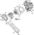
- the system comprises the housing 15 made of rigid plastic material.
- the housing 15 comprises a front part 24 and a rear cover 26 assembled to one another.
- the front part 24 can geometrically be divided between an inner region and an outer region. The separation between the inner and outer regions can for example be defined by the geometry of the connection interface with the plug. Since the free space 12 receives the outer connection shape of the plug, the inner space of the front part 24 is located inside this free space 12.
- the inner body 11 is located in the inner region.
- the outer shell 13 is located in the outer region.
- the inner body 11 comprises the surrounding wall 16, which surrounds the plurality of receptacles 17. Each receptacle 17 is shaped to receive an electrical contact 18.
- Each electrical contact 18 is assembled to an electric wire 19 which is part of the cable 3.
- Each electrical wire 19 comprises an electrically conducting core 20 surrounded by an electrically insulating sheath 21.
- the electrical contact 18 is assembled in a suitable way into the receptacle 17 of the housing 15.
- the electrical connection system 101 comprises a rear holder 22, which is assembled to the rear of the front part 24.
- This assembly is for example made by snap-fitting an elastic leg 25 of the rear holder 22 to projecting pegs 35 at the rear of the front part 24.
- the contacts 18 are snap-fitted to the rear holder 22, for example using elastic lances 23 of the rear holder which cooperate with grooves 36 of the contacts 18.
- the housing further comprises a rear cover 26 which is assembled to the front part 24. It has an outer wall.
- the rear cover 26 is for example a right-angled cover, which comprises a front opening facing the rear of the front part 24, and a rear opening 37 oriented at 90° with respect to the front opening.
- the bundle of wires 19 enters the rear cover 26 through the rear opening, and exits it through the front opening.
- the rear cover 26 is for example assembled by screwing to the front part 24 through the rear holder 22 using screws 30 in threaded holes 38.
- the connection system is provided with a seal 27.
- the seal 27 is a flat seal extending peripherally as a ring.
- One front face 27a contacts a rear face 24b of the front part 24.
- the opposite rear face 27b is pressed upon by the cover 26 all around the periphery.
- the rear holder 22 may also peripherally contact the rear face 27b of the seal, as visible on Fig. 5 .
- the screw 30 can be assembled through the seal 27, to prevent any water from flowing through the screw connection.
- the seal 27 has a screw hole 38 to receive the bottom screw 30.
- an elastomer sheath 28 is sealingly assembled to the rear cover 26.
- the elastomer sheath has a front end 28a and an opposed rear end 28b. The front end for example surrounds and tightly fits on the rear opening 37 of the rear cover.
- the rear end of the sheath 28 is sealingly assembled to the wires 19, either individually, or through an insulating sheath 39 which gathers together the electrical wires (visible on Fig. 3 ), and having an outer surface 40.
- the electrical wire 19 is not assembled in the housing 15 in a waterproof way.
- a water drain 29 in the receptacle so that water provided inside the cavity 17 is allowed to flow inside the cover 26 and along the outer surface of the wires through the rear opening of the rear cover 26 inside the sheath 28.
- water which finds itself in a receptacle 17 is prohibited from flowing out of a barrier comprising the wall 16 of the front part 24, the seal 27, the cover 26 and the sheath 28.
- the outer wall 12 may further comprise a water drain 32.
- the water drain will be provided at the lowest part of the housing, assuming the car is loaded parking on a horizontal surface.
- the outer wall 12 may further be provided with a water drain 33 in the top area. This water drain 33 will make it easier, for water coming from the top (e.g. rain) to be preferentially guided inside the free space 13, and hence toward the bottom water drain 32. Following the law of gravity, rain water is not allowed to flow on the top surface of the rear cover 26.
- the flow paths of water touching the contacts on the vehicle side, and hence charged with power will not cross the flow paths touching the hand of the user handling the charging plug, thus providing enhanced security to the user.
- the flow path touching the hand of the user may flow inside the inner free space 12, where gravity will lead it to the drain hole 32.
- the front top edge 50 of the housing acts as a water parting line. This is true even if the housing comprises a front grid 51 attached to the front part 24 as in the present example.
Landscapes
- Engineering & Computer Science (AREA)
- Power Engineering (AREA)
- Transportation (AREA)
- Mechanical Engineering (AREA)
- Life Sciences & Earth Sciences (AREA)
- Sustainable Development (AREA)
- Sustainable Energy (AREA)
- Connector Housings Or Holding Contact Members (AREA)
Claims (7)
- Elektrisches Verbindungssystem, das aufweist:- eine elektrische Einrichtung (100) mit einem ersten Verbindungssystem (101),- ein elektrisches Ladegerät (200) mit einem zweiten Verbindungssystem (2), wobei das erste und das zweite Verbindungssystem miteinander verbindbar sind zum Übertragen von Elektrizität von dem Ladegerät zu der Einrichtung, wobei das erste Verbindungssystem aufweist:- ein Gehäuse (15) mit einer starren Außenwand (16), die einen inneren Bereich umgibt, in dem zumindest eine Aufnahme (17) definiert ist, wobei das Gehäuse einen vorderen Bereich hat in einer Form zum Verbinden mit dem zweiten Verbindungssystem ohne Intervention einer verformbaren Dichtung,- ein elektrisches Kabel (3), das eine externe Isolierhülle (39) und zumindest einen elektrischen Draht (19) aufweist, wobei die Isolierhülle eine äußere Oberfläche hat, wobei jeder elektrische Draht einen elektrischen Kern (20) aufweist, und einen Anschluss (18), der an dem elektrischen Kern befestigt ist und in einer jeweiligen Aufnahme des Gehäuses angebracht ist, dadurch gekennzeichnet, dass
sich eine periphere Abdichtungsbarriere von der Außenwand (16) an dem vorderen Bereich des Gehäuses zu der Außenfläche (21, 40) der externen Isolierhülle (39) erstreckt,
das Gehäuse einen vorderen Teil (24) mit dem vorderen Bereich und eine hintere Abdeckung (26) aufweist, die mit dem vorderen Teil zusammengefügt ist, wobei die hintere Abdeckung eine vordere Öffnung aufweist, durch die sich der Anschluss (18) erstreckt, und eine hintere Öffnung (37), durch die sich die Isolierhülle (39) erstreckt,
wobei das System weiter eine hintere Dichtung (27) aufweist, die zwischen dem vorderen Teil und der hinteren Abdeckung des Gehäuses komprimiert ist, wobei das System weiter eine elastomere Hülle (28) aufweist, die sich in Längsrichtung von der Außenfläche der Isolierhülle (39) des elektrischen Kabels (3) zu der hinteren Abdeckung (26) des Gehäuses erstreckt und abdichtend an der hinteren Öffnung der hinteren Abdeckung (26) angebracht ist, dass die periphere Abdichtungsbarriere die Außenwand (16), die hintere Dichtung (27), eine Außenwand des hinteren Teils (26) und die elastomere Hülle (28) aufweist, die die Außenwand der hinteren Abdeckung (26) kontaktiert und umgibt. - Elektrisches Verbindungssystem gemäß Anspruch 1, das weiter ein Verriegelungssystem (30, 38) zum Verriegeln des vorderen Teils an der hinteren Abdeckung aufweist.
- Elektrisches Verbindungssystem gemäß einem der Ansprüche 1 bis 2, wobei sich die Isolierhülle (39) durch die hintere Öffnung (37) erstreckt.
- Elektrisches Verbindungssystem gemäß einem der Ansprüche 1 bis 3, das weiter zumindest einen Wasserablauf (32) in dem Gehäuse aufweist, außerhalb eines durch die Abdichtungsbarriere definierten Innenraums.
- Elektrisches Verbindungssystem gemäß einem der Ansprüche 1 bis 4, das weiter zumindest einen Wasserablauf (29) in der Aufnahme aufweist, innerhalb eines durch die Abdichtungsbarriere definierten Innenraums.
- Elektrisches Verbindungssystem gemäß einem der Ansprüche 1 bis 5, das weiter einen Kontakthalter (22) innerhalb eines durch die Abdichtungsbarriere definierten Innenraums aufweist, wobei der Kontakt in der Aufnahme mit dem Kontakthalter gehalten wird.
- Elektrisches Verbindungssystem gemäß einem der Ansprüche 1 bis 6, wobei das zweite Verbindungssystem eine äußere Umhüllung (4) für ein Greifen durch den Benutzer aufweist.
Priority Applications (1)
| Application Number | Priority Date | Filing Date | Title |
|---|---|---|---|
| EP13305339.7A EP2782192B1 (de) | 2013-03-20 | 2013-03-20 | Elektrisches Verbindungssystem |
Applications Claiming Priority (1)
| Application Number | Priority Date | Filing Date | Title |
|---|---|---|---|
| EP13305339.7A EP2782192B1 (de) | 2013-03-20 | 2013-03-20 | Elektrisches Verbindungssystem |
Publications (2)
| Publication Number | Publication Date |
|---|---|
| EP2782192A1 EP2782192A1 (de) | 2014-09-24 |
| EP2782192B1 true EP2782192B1 (de) | 2017-11-08 |
Family
ID=48040128
Family Applications (1)
| Application Number | Title | Priority Date | Filing Date |
|---|---|---|---|
| EP13305339.7A Active EP2782192B1 (de) | 2013-03-20 | 2013-03-20 | Elektrisches Verbindungssystem |
Country Status (1)
| Country | Link |
|---|---|
| EP (1) | EP2782192B1 (de) |
Families Citing this family (3)
| Publication number | Priority date | Publication date | Assignee | Title |
|---|---|---|---|---|
| CN106218438B (zh) * | 2016-09-14 | 2018-11-06 | 恒大法拉第未来智能汽车(广东)有限公司 | 充电装置及具有该充电装置的车辆 |
| CN113544915A (zh) * | 2019-03-07 | 2021-10-22 | 尼科公司 | 电气端口装置 |
| CN117863932B (zh) * | 2024-02-01 | 2024-08-27 | 国网湖北省电力有限公司荆州供电公司 | 一种防触电的新能源汽车充电桩 |
Family Cites Families (2)
| Publication number | Priority date | Publication date | Assignee | Title |
|---|---|---|---|---|
| JP5312370B2 (ja) * | 2010-02-23 | 2013-10-09 | トヨタ自動車株式会社 | インレット組立体 |
| KR20120025837A (ko) * | 2010-09-08 | 2012-03-16 | 엘에스전선 주식회사 | 전기자동차 충전용 커넥터 |
-
2013
- 2013-03-20 EP EP13305339.7A patent/EP2782192B1/de active Active
Non-Patent Citations (1)
| Title |
|---|
| None * |
Also Published As
| Publication number | Publication date |
|---|---|
| EP2782192A1 (de) | 2014-09-24 |
Similar Documents
| Publication | Publication Date | Title |
|---|---|---|
| US9090172B2 (en) | Charging stations for use in charging electrically powered vehicles and related methods | |
| US10290969B2 (en) | Sealing element, seal assembly and receptacle | |
| US9415695B2 (en) | Electric vehicle charger | |
| US20180269619A1 (en) | Car charging plug-in connector | |
| US20120238147A1 (en) | Connector assembly | |
| US10263356B2 (en) | Secondary lock and receptacle | |
| US20110111612A1 (en) | Electrical connector assembly with sealing washer | |
| JP2016526777A (ja) | 電気車両又はハイブリッド車両用の電気プラグ型コネクタ及びプラグ型コネクタシステム | |
| CN103582983A (zh) | 连接器 | |
| US20180331463A1 (en) | Receptacle housing and receptacle | |
| KR102311636B1 (ko) | 고전압 직체결 커넥터 및 그 연결구조 | |
| CN101807767B (zh) | 用于附接至电子模块的触点组件 | |
| JP2018085201A5 (de) | ||
| CN208240973U (zh) | 一种交流充电枪 | |
| CN110323592B (zh) | 电连接器、电气单元以及车辆 | |
| EP2782192B1 (de) | Elektrisches Verbindungssystem | |
| CN102222849B (zh) | 防爆电连接装置及其插头、插座 | |
| US7897275B2 (en) | Electrical rechargeable battery | |
| CN107039820B (zh) | 插座装置,机动车 | |
| CN217983874U (zh) | 一种防水电路连接器 | |
| EP4215407B1 (de) | Stecker und steckdose eines ladegerätverlängerungskabels für elektrofahrzeuge | |
| KR20200079915A (ko) | 차량용 패널의 태양전지모듈 및 그를 포함하는 차량용 패널 어셈블리 | |
| US20110111613A1 (en) | Rotatable power adapter | |
| CN110416836A (zh) | 电连接器和具有其的车辆 | |
| KR101448252B1 (ko) | 배터리 홀더 시스템 및 배터리 단자 커버를 포함하는 배터리 |
Legal Events
| Date | Code | Title | Description |
|---|---|---|---|
| PUAI | Public reference made under article 153(3) epc to a published international application that has entered the european phase |
Free format text: ORIGINAL CODE: 0009012 |
|
| 17P | Request for examination filed |
Effective date: 20130320 |
|
| AK | Designated contracting states |
Kind code of ref document: A1 Designated state(s): AL AT BE BG CH CY CZ DE DK EE ES FI FR GB GR HR HU IE IS IT LI LT LU LV MC MK MT NL NO PL PT RO RS SE SI SK SM TR |
|
| AX | Request for extension of the european patent |
Extension state: BA ME |
|
| R17P | Request for examination filed (corrected) |
Effective date: 20150324 |
|
| RBV | Designated contracting states (corrected) |
Designated state(s): AL AT BE BG CH CY CZ DE DK EE ES FI FR GB GR HR HU IE IS IT LI LT LU LV MC MK MT NL NO PL PT RO RS SE SI SK SM TR |
|
| 17Q | First examination report despatched |
Effective date: 20170228 |
|
| GRAP | Despatch of communication of intention to grant a patent |
Free format text: ORIGINAL CODE: EPIDOSNIGR1 |
|
| RIC1 | Information provided on ipc code assigned before grant |
Ipc: B60L 11/18 20060101ALI20170509BHEP Ipc: B60L 3/00 20060101ALI20170509BHEP Ipc: H01R 13/52 20060101AFI20170509BHEP |
|
| INTG | Intention to grant announced |
Effective date: 20170524 |
|
| RIN1 | Information on inventor provided before grant (corrected) |
Inventor name: MALANDAIN, OLIVIER Inventor name: CHARVET, SEBASTIEN |
|
| GRAS | Grant fee paid |
Free format text: ORIGINAL CODE: EPIDOSNIGR3 |
|
| GRAA | (expected) grant |
Free format text: ORIGINAL CODE: 0009210 |
|
| AK | Designated contracting states |
Kind code of ref document: B1 Designated state(s): AL AT BE BG CH CY CZ DE DK EE ES FI FR GB GR HR HU IE IS IT LI LT LU LV MC MK MT NL NO PL PT RO RS SE SI SK SM TR |
|
| REG | Reference to a national code |
Ref country code: GB Ref legal event code: FG4D |
|
| REG | Reference to a national code |
Ref country code: CH Ref legal event code: EP Ref country code: AT Ref legal event code: REF Ref document number: 945019 Country of ref document: AT Kind code of ref document: T Effective date: 20171115 |
|
| REG | Reference to a national code |
Ref country code: IE Ref legal event code: FG4D |
|
| REG | Reference to a national code |
Ref country code: DE Ref legal event code: R096 Ref document number: 602013029045 Country of ref document: DE |
|
| REG | Reference to a national code |
Ref country code: NL Ref legal event code: MP Effective date: 20171108 |
|
| REG | Reference to a national code |
Ref country code: LT Ref legal event code: MG4D Ref country code: FR Ref legal event code: PLFP Year of fee payment: 6 |
|
| REG | Reference to a national code |
Ref country code: AT Ref legal event code: MK05 Ref document number: 945019 Country of ref document: AT Kind code of ref document: T Effective date: 20171108 |
|
| PG25 | Lapsed in a contracting state [announced via postgrant information from national office to epo] |
Ref country code: SE Free format text: LAPSE BECAUSE OF FAILURE TO SUBMIT A TRANSLATION OF THE DESCRIPTION OR TO PAY THE FEE WITHIN THE PRESCRIBED TIME-LIMIT Effective date: 20171108 Ref country code: LT Free format text: LAPSE BECAUSE OF FAILURE TO SUBMIT A TRANSLATION OF THE DESCRIPTION OR TO PAY THE FEE WITHIN THE PRESCRIBED TIME-LIMIT Effective date: 20171108 Ref country code: FI Free format text: LAPSE BECAUSE OF FAILURE TO SUBMIT A TRANSLATION OF THE DESCRIPTION OR TO PAY THE FEE WITHIN THE PRESCRIBED TIME-LIMIT Effective date: 20171108 Ref country code: NL Free format text: LAPSE BECAUSE OF FAILURE TO SUBMIT A TRANSLATION OF THE DESCRIPTION OR TO PAY THE FEE WITHIN THE PRESCRIBED TIME-LIMIT Effective date: 20171108 Ref country code: NO Free format text: LAPSE BECAUSE OF FAILURE TO SUBMIT A TRANSLATION OF THE DESCRIPTION OR TO PAY THE FEE WITHIN THE PRESCRIBED TIME-LIMIT Effective date: 20180208 Ref country code: ES Free format text: LAPSE BECAUSE OF FAILURE TO SUBMIT A TRANSLATION OF THE DESCRIPTION OR TO PAY THE FEE WITHIN THE PRESCRIBED TIME-LIMIT Effective date: 20171108 |
|
| PG25 | Lapsed in a contracting state [announced via postgrant information from national office to epo] |
Ref country code: HR Free format text: LAPSE BECAUSE OF FAILURE TO SUBMIT A TRANSLATION OF THE DESCRIPTION OR TO PAY THE FEE WITHIN THE PRESCRIBED TIME-LIMIT Effective date: 20171108 Ref country code: BG Free format text: LAPSE BECAUSE OF FAILURE TO SUBMIT A TRANSLATION OF THE DESCRIPTION OR TO PAY THE FEE WITHIN THE PRESCRIBED TIME-LIMIT Effective date: 20180208 Ref country code: IS Free format text: LAPSE BECAUSE OF FAILURE TO SUBMIT A TRANSLATION OF THE DESCRIPTION OR TO PAY THE FEE WITHIN THE PRESCRIBED TIME-LIMIT Effective date: 20180308 Ref country code: LV Free format text: LAPSE BECAUSE OF FAILURE TO SUBMIT A TRANSLATION OF THE DESCRIPTION OR TO PAY THE FEE WITHIN THE PRESCRIBED TIME-LIMIT Effective date: 20171108 Ref country code: AT Free format text: LAPSE BECAUSE OF FAILURE TO SUBMIT A TRANSLATION OF THE DESCRIPTION OR TO PAY THE FEE WITHIN THE PRESCRIBED TIME-LIMIT Effective date: 20171108 Ref country code: RS Free format text: LAPSE BECAUSE OF FAILURE TO SUBMIT A TRANSLATION OF THE DESCRIPTION OR TO PAY THE FEE WITHIN THE PRESCRIBED TIME-LIMIT Effective date: 20171108 Ref country code: GR Free format text: LAPSE BECAUSE OF FAILURE TO SUBMIT A TRANSLATION OF THE DESCRIPTION OR TO PAY THE FEE WITHIN THE PRESCRIBED TIME-LIMIT Effective date: 20180209 |
|
| PG25 | Lapsed in a contracting state [announced via postgrant information from national office to epo] |
Ref country code: CZ Free format text: LAPSE BECAUSE OF FAILURE TO SUBMIT A TRANSLATION OF THE DESCRIPTION OR TO PAY THE FEE WITHIN THE PRESCRIBED TIME-LIMIT Effective date: 20171108 Ref country code: SK Free format text: LAPSE BECAUSE OF FAILURE TO SUBMIT A TRANSLATION OF THE DESCRIPTION OR TO PAY THE FEE WITHIN THE PRESCRIBED TIME-LIMIT Effective date: 20171108 Ref country code: DK Free format text: LAPSE BECAUSE OF FAILURE TO SUBMIT A TRANSLATION OF THE DESCRIPTION OR TO PAY THE FEE WITHIN THE PRESCRIBED TIME-LIMIT Effective date: 20171108 Ref country code: CY Free format text: LAPSE BECAUSE OF FAILURE TO SUBMIT A TRANSLATION OF THE DESCRIPTION OR TO PAY THE FEE WITHIN THE PRESCRIBED TIME-LIMIT Effective date: 20171108 Ref country code: EE Free format text: LAPSE BECAUSE OF FAILURE TO SUBMIT A TRANSLATION OF THE DESCRIPTION OR TO PAY THE FEE WITHIN THE PRESCRIBED TIME-LIMIT Effective date: 20171108 |
|
| REG | Reference to a national code |
Ref country code: DE Ref legal event code: R097 Ref document number: 602013029045 Country of ref document: DE |
|
| PG25 | Lapsed in a contracting state [announced via postgrant information from national office to epo] |
Ref country code: RO Free format text: LAPSE BECAUSE OF FAILURE TO SUBMIT A TRANSLATION OF THE DESCRIPTION OR TO PAY THE FEE WITHIN THE PRESCRIBED TIME-LIMIT Effective date: 20171108 Ref country code: SM Free format text: LAPSE BECAUSE OF FAILURE TO SUBMIT A TRANSLATION OF THE DESCRIPTION OR TO PAY THE FEE WITHIN THE PRESCRIBED TIME-LIMIT Effective date: 20171108 Ref country code: IT Free format text: LAPSE BECAUSE OF FAILURE TO SUBMIT A TRANSLATION OF THE DESCRIPTION OR TO PAY THE FEE WITHIN THE PRESCRIBED TIME-LIMIT Effective date: 20171108 Ref country code: PL Free format text: LAPSE BECAUSE OF FAILURE TO SUBMIT A TRANSLATION OF THE DESCRIPTION OR TO PAY THE FEE WITHIN THE PRESCRIBED TIME-LIMIT Effective date: 20171108 |
|
| PLBE | No opposition filed within time limit |
Free format text: ORIGINAL CODE: 0009261 |
|
| STAA | Information on the status of an ep patent application or granted ep patent |
Free format text: STATUS: NO OPPOSITION FILED WITHIN TIME LIMIT |
|
| 26N | No opposition filed |
Effective date: 20180809 |
|
| REG | Reference to a national code |
Ref country code: CH Ref legal event code: PL |
|
| PG25 | Lapsed in a contracting state [announced via postgrant information from national office to epo] |
Ref country code: MC Free format text: LAPSE BECAUSE OF FAILURE TO SUBMIT A TRANSLATION OF THE DESCRIPTION OR TO PAY THE FEE WITHIN THE PRESCRIBED TIME-LIMIT Effective date: 20171108 Ref country code: SI Free format text: LAPSE BECAUSE OF FAILURE TO SUBMIT A TRANSLATION OF THE DESCRIPTION OR TO PAY THE FEE WITHIN THE PRESCRIBED TIME-LIMIT Effective date: 20171108 |
|
| REG | Reference to a national code |
Ref country code: BE Ref legal event code: MM Effective date: 20180331 |
|
| REG | Reference to a national code |
Ref country code: DE Ref legal event code: R081 Ref document number: 602013029045 Country of ref document: DE Owner name: APTIV TECHNOLOGIES LIMITED, BB Free format text: FORMER OWNER: DELPHI INTERNATIONAL OPERATIONS LUXEMBOURG S.A R.L., BASCHARAGE, LU |
|
| REG | Reference to a national code |
Ref country code: IE Ref legal event code: MM4A |
|
| PG25 | Lapsed in a contracting state [announced via postgrant information from national office to epo] |
Ref country code: LU Free format text: LAPSE BECAUSE OF NON-PAYMENT OF DUE FEES Effective date: 20180320 |
|
| REG | Reference to a national code |
Ref country code: GB Ref legal event code: 732E Free format text: REGISTERED BETWEEN 20181213 AND 20181219 |
|
| PG25 | Lapsed in a contracting state [announced via postgrant information from national office to epo] |
Ref country code: IE Free format text: LAPSE BECAUSE OF NON-PAYMENT OF DUE FEES Effective date: 20180320 |
|
| PG25 | Lapsed in a contracting state [announced via postgrant information from national office to epo] |
Ref country code: BE Free format text: LAPSE BECAUSE OF NON-PAYMENT OF DUE FEES Effective date: 20180331 Ref country code: LI Free format text: LAPSE BECAUSE OF NON-PAYMENT OF DUE FEES Effective date: 20180331 Ref country code: CH Free format text: LAPSE BECAUSE OF NON-PAYMENT OF DUE FEES Effective date: 20180331 |
|
| PG25 | Lapsed in a contracting state [announced via postgrant information from national office to epo] |
Ref country code: MT Free format text: LAPSE BECAUSE OF NON-PAYMENT OF DUE FEES Effective date: 20180320 |
|
| PG25 | Lapsed in a contracting state [announced via postgrant information from national office to epo] |
Ref country code: TR Free format text: LAPSE BECAUSE OF FAILURE TO SUBMIT A TRANSLATION OF THE DESCRIPTION OR TO PAY THE FEE WITHIN THE PRESCRIBED TIME-LIMIT Effective date: 20171108 |
|
| PG25 | Lapsed in a contracting state [announced via postgrant information from national office to epo] |
Ref country code: HU Free format text: LAPSE BECAUSE OF FAILURE TO SUBMIT A TRANSLATION OF THE DESCRIPTION OR TO PAY THE FEE WITHIN THE PRESCRIBED TIME-LIMIT; INVALID AB INITIO Effective date: 20130320 Ref country code: PT Free format text: LAPSE BECAUSE OF FAILURE TO SUBMIT A TRANSLATION OF THE DESCRIPTION OR TO PAY THE FEE WITHIN THE PRESCRIBED TIME-LIMIT Effective date: 20171108 |
|
| PG25 | Lapsed in a contracting state [announced via postgrant information from national office to epo] |
Ref country code: MK Free format text: LAPSE BECAUSE OF NON-PAYMENT OF DUE FEES Effective date: 20171108 |
|
| PG25 | Lapsed in a contracting state [announced via postgrant information from national office to epo] |
Ref country code: AL Free format text: LAPSE BECAUSE OF FAILURE TO SUBMIT A TRANSLATION OF THE DESCRIPTION OR TO PAY THE FEE WITHIN THE PRESCRIBED TIME-LIMIT Effective date: 20171108 |
|
| P01 | Opt-out of the competence of the unified patent court (upc) registered |
Effective date: 20230425 |
|
| REG | Reference to a national code |
Ref country code: DE Ref legal event code: R081 Ref document number: 602013029045 Country of ref document: DE Owner name: APTIV TECHNOLOGIES AG, CH Free format text: FORMER OWNER: APTIV TECHNOLOGIES LIMITED, ST. MICHAEL, BB |
|
| PGFP | Annual fee paid to national office [announced via postgrant information from national office to epo] |
Ref country code: GB Payment date: 20260223 Year of fee payment: 14 |
|
| PGFP | Annual fee paid to national office [announced via postgrant information from national office to epo] |
Ref country code: DE Payment date: 20260223 Year of fee payment: 14 |
|
| PGFP | Annual fee paid to national office [announced via postgrant information from national office to epo] |
Ref country code: FR Payment date: 20260303 Year of fee payment: 14 |