EP2782974B1 - Dispositif destine a de l'imagerie neutronique en milieu immerge et procede d'imagerie utilisant ledit dispositif - Google Patents
Dispositif destine a de l'imagerie neutronique en milieu immerge et procede d'imagerie utilisant ledit dispositif Download PDFInfo
- Publication number
- EP2782974B1 EP2782974B1 EP12790887.9A EP12790887A EP2782974B1 EP 2782974 B1 EP2782974 B1 EP 2782974B1 EP 12790887 A EP12790887 A EP 12790887A EP 2782974 B1 EP2782974 B1 EP 2782974B1
- Authority
- EP
- European Patent Office
- Prior art keywords
- converter
- neutron
- radiation
- support
- neutron imaging
- Prior art date
- Legal status (The legal status is an assumption and is not a legal conclusion. Google has not performed a legal analysis and makes no representation as to the accuracy of the status listed.)
- Active
Links
Images

Classifications
-
- G—PHYSICS
- G01—MEASURING; TESTING
- G01N—INVESTIGATING OR ANALYSING MATERIALS BY DETERMINING THEIR CHEMICAL OR PHYSICAL PROPERTIES
- G01N23/00—Investigating or analysing materials by the use of wave or particle radiation, e.g. X-rays or neutrons, not covered by groups G01N3/00 – G01N17/00, G01N21/00 or G01N22/00
- G01N23/02—Investigating or analysing materials by the use of wave or particle radiation, e.g. X-rays or neutrons, not covered by groups G01N3/00 – G01N17/00, G01N21/00 or G01N22/00 by transmitting the radiation through the material
- G01N23/04—Investigating or analysing materials by the use of wave or particle radiation, e.g. X-rays or neutrons, not covered by groups G01N3/00 – G01N17/00, G01N21/00 or G01N22/00 by transmitting the radiation through the material and forming images of the material
- G01N23/05—Investigating or analysing materials by the use of wave or particle radiation, e.g. X-rays or neutrons, not covered by groups G01N3/00 – G01N17/00, G01N21/00 or G01N22/00 by transmitting the radiation through the material and forming images of the material using neutrons
-
- C—CHEMISTRY; METALLURGY
- C09—DYES; PAINTS; POLISHES; NATURAL RESINS; ADHESIVES; COMPOSITIONS NOT OTHERWISE PROVIDED FOR; APPLICATIONS OF MATERIALS NOT OTHERWISE PROVIDED FOR
- C09K—MATERIALS FOR MISCELLANEOUS APPLICATIONS, NOT PROVIDED FOR ELSEWHERE
- C09K11/00—Luminescent materials, e.g. electroluminescent or chemiluminescent
- C09K11/02—Use of particular materials as binders, particle coatings or suspension media therefor
-
- C—CHEMISTRY; METALLURGY
- C09—DYES; PAINTS; POLISHES; NATURAL RESINS; ADHESIVES; COMPOSITIONS NOT OTHERWISE PROVIDED FOR; APPLICATIONS OF MATERIALS NOT OTHERWISE PROVIDED FOR
- C09K—MATERIALS FOR MISCELLANEOUS APPLICATIONS, NOT PROVIDED FOR ELSEWHERE
- C09K11/00—Luminescent materials, e.g. electroluminescent or chemiluminescent
- C09K11/08—Luminescent materials, e.g. electroluminescent or chemiluminescent containing inorganic luminescent materials
- C09K11/77—Luminescent materials, e.g. electroluminescent or chemiluminescent containing inorganic luminescent materials containing rare earth metals
-
- C—CHEMISTRY; METALLURGY
- C09—DYES; PAINTS; POLISHES; NATURAL RESINS; ADHESIVES; COMPOSITIONS NOT OTHERWISE PROVIDED FOR; APPLICATIONS OF MATERIALS NOT OTHERWISE PROVIDED FOR
- C09K—MATERIALS FOR MISCELLANEOUS APPLICATIONS, NOT PROVIDED FOR ELSEWHERE
- C09K11/00—Luminescent materials, e.g. electroluminescent or chemiluminescent
- C09K11/08—Luminescent materials, e.g. electroluminescent or chemiluminescent containing inorganic luminescent materials
- C09K11/77—Luminescent materials, e.g. electroluminescent or chemiluminescent containing inorganic luminescent materials containing rare earth metals
- C09K11/7783—Luminescent materials, e.g. electroluminescent or chemiluminescent containing inorganic luminescent materials containing rare earth metals containing two or more rare earth metals one of which being europium
- C09K11/7784—Chalcogenides
- C09K11/7787—Oxides
- C09K11/7789—Oxysulfides
-
- G—PHYSICS
- G01—MEASURING; TESTING
- G01N—INVESTIGATING OR ANALYSING MATERIALS BY DETERMINING THEIR CHEMICAL OR PHYSICAL PROPERTIES
- G01N23/00—Investigating or analysing materials by the use of wave or particle radiation, e.g. X-rays or neutrons, not covered by groups G01N3/00 – G01N17/00, G01N21/00 or G01N22/00
- G01N23/02—Investigating or analysing materials by the use of wave or particle radiation, e.g. X-rays or neutrons, not covered by groups G01N3/00 – G01N17/00, G01N21/00 or G01N22/00 by transmitting the radiation through the material
- G01N23/04—Investigating or analysing materials by the use of wave or particle radiation, e.g. X-rays or neutrons, not covered by groups G01N3/00 – G01N17/00, G01N21/00 or G01N22/00 by transmitting the radiation through the material and forming images of the material
- G01N23/043—Investigating or analysing materials by the use of wave or particle radiation, e.g. X-rays or neutrons, not covered by groups G01N3/00 – G01N17/00, G01N21/00 or G01N22/00 by transmitting the radiation through the material and forming images of the material using fluoroscopic examination, with visual observation or video transmission of fluoroscopic images
-
- G—PHYSICS
- G01—MEASURING; TESTING
- G01T—MEASUREMENT OF NUCLEAR OR X-RADIATION
- G01T3/00—Measuring neutron radiation
- G01T3/06—Measuring neutron radiation with scintillation detectors
-
- G—PHYSICS
- G21—NUCLEAR PHYSICS; NUCLEAR ENGINEERING
- G21K—HANDLING OF PARTICLES OR IONISING RADIATION NOT OTHERWISE PROVIDED FOR; IRRADIATION DEVICES; GAMMA RAY OR X-RAY MICROSCOPES
- G21K4/00—Conversion screens for the conversion of the spatial distribution of X-rays or particle radiation into visible images, e.g. fluoroscopic screens
-
- G—PHYSICS
- G01—MEASURING; TESTING
- G01N—INVESTIGATING OR ANALYSING MATERIALS BY DETERMINING THEIR CHEMICAL OR PHYSICAL PROPERTIES
- G01N2223/00—Investigating materials by wave or particle radiation
- G01N2223/60—Specific applications or type of materials
- G01N2223/625—Specific applications or type of materials nuclear fuels, laser imploded targets
Definitions
- the field of the invention is that of non-destructive control of irradiating objects and using neutron imaging.
- Neutronography is a non-destructive testing technique analogous in principle to X-ray radiography.
- a neutron beam shaped from a source is used to provide a transparency image of the object being examined.
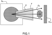
- a typical neutronography installation can be schematized by the figure 1 which highlights: a neutron source S N placed in a moderating medium, intended to lower the energy of the neutrons that are produced. At a calculated distance from this source is disposed the input window of a collimator C which shapes the beam. In this figure, a collimator of divergent shape is shown. The collimator is equipped with a filter F of material to block the gamma radiation that can accompany the neutron emission. The collimator has internal neutron absorbing walls and a neutron-transparent filling gas. At the output of the collimator, the neutrons interact with the object under examination Ob, those transmitted therethrough are absorbed by a detector D ect to form the image.
- moderator element is indeed necessary in the measurement generally where the neutron sources emit a fast neutron spectrum which is very rarely adapted to make the imagery. It is then necessary to slow the neutrons in a medium called moderator surrounding the fast source. This process unfortunately leads to considerable losses of intensity because the moderator is not totally transparent to neutrons and parasitic captures always occur there. In the moderator, the neutrons are slowed down by successive shocks accompanied by energy transfers to the middle atoms.
- the object thus analyzed and traversed by a neutron flux generates an image of its own. Indeed, the interaction of neutrons in matter is characterized by diffusion and absorption phenomena. Neutrons have in particular the ability to detect hydrogen atoms in media through metallic structures, the analysis can be conducted by the spatial and temporal attenuation of the neutron beam.
- neutronography in the reactor pool in which the imaging system is installed closer to the reactor core within the pool itself (the system is immersed in the water). This is the case, for example, with the OSIRIS neutronography system in France or the HFR at Petten in the Netherlands) and out-of-reactor neutron imaging, in which the neutron beam is extracted from the reactor to form a beam emerging from the reactor pool ( ORPHEE neutronography system for example).
- OSIRIS is an experimental reactor with a thermal output of 70 megawatts. It is an open-water, light-water pool type reactor whose main purpose is to perform tests and to irradiate under high neutron flux the fuel elements and structural materials of nuclear power plants as well as produce radioelements.
- the adapted neutron system is a submerged neutron, for obvious reasons related to the irradiance of the object under examination.
- This method allowing to keep only the neutron signal is thus based on a production of the image in two stages, after a transfer of a part of the system outside the reactor pool: an activatable converter is exposed to the neutron flux downstream of the reactor. inspected object, then this converter is transferred out of the pool to image its activity (beta activity), which provides a transmission image of the neutron absorption of the inspected object.
- Beta activity provides a transmission image of the neutron absorption of the inspected object.
- the current transfer neutronography methods require the application of a primary neutron neutron convertor to residual beta radiation, on a second image producing system (radiographic film or radio-luminescent memory screen), involving the need for a contact as perfect as possible between the two elements to optimize the resolution of the image (use of a vacuum box, ...) and many manipulations of the operator.
- a second image producing system radio-luminescent memory screen
- the patent US3891852 relates to the detection of neutrons and the recording of neutron images, using a screen containing a gadolinium compound becoming fluorescent when struck by rays and a photosensitive material on which is projected the fluorescent light resulting from the neutron shock on the screen. It may include another neutron absorbing screen, for example a dysprosium screen used in conjunction with the gadolinium screen.
- the subject of the present invention is a new type of device intended to be immersed in order to perform non-destructive control operations. destructive by sophisticated neutron imaging of species, including irradiated nuclear fuels.
- the present invention may advantageously relate to submerged neutronography in a reactor pool (aimed in particular at a application to the future neutronography system of the RJH reactor) by proposing a device for obtaining a high resolution neutron imaging image, in a medium with high neutron flux and high gamma flux, in a reactor pool, and this by a transferable system out pool, ensuring minimal activation of the associated structures to ensure the best radiation protection of the operator handling said transferred imaging system.
- the subject of the present invention is a device intended to be used for performing neutron imaging by immersion in a medium containing species to be analyzed, characterized in that it comprises a first converter comprising a first material capable of converting a neutron radiation in remnant beta radiation, and a second converter comprising a second material capable of converting residual beta radiation to light radiation, said second converter being in continuous contact with said first converter.
- Said device further comprises a support comprising hydrogenated species on which said first and second converters are positioned, said support being transparent to said light radiation.
- Said first material comprises dysprosium.
- Said second converter comprises a scintillator material which is a gadolinium-based compound which can be of the Gd 2 O 2 S (Tb) type (which can be doped with terbium).
- a scintillator material which is a gadolinium-based compound which can be of the Gd 2 O 2 S (Tb) type (which can be doped with terbium).
- the scintillator material is mixed with an organic binder.
- the thickness of the first converter is of the order of a hundred microns.
- the thickness of the second converter is of the order of ten microns.
- the transparent support comprising hydrogenated species is of polymethyl methacrylate type, which may have a thickness of the order of a few millimeters.
- the invention also relates to a sealed system comprising a chamber to said environment, incorporating the device according to the invention.
- the box is made of a weakly activatable material by a neutron flux, which may be an aluminum alloy.
- the object to be analyzed is not itself directly in the liquid medium which may be water, it is introduced into a chamber, located between the end of a collimator and the irradiation cassette. This room is filled with compressed air to drive water away.
- the species to be analyzed are irradiated or non-irradiated nuclear fuels in the case of neutron examination carried out before irradiation.
- the present invention will be described in the context of the neutron imaging analysis of irradiating objects in a pool reactor but may also be declined in the case of non-destructive species control immersed in a medium.
- the figure 2 illustrates an example of a device used in the present invention and intended to be immersed in the pool of a reactor producing neutrons.
- the device comprises a first converter C 1 , a second converter C 2 , in contact with the first converter.
- the second converter is on the surface of a support S 3 .
- a neutron flux F N crosses the entire device, it encounters neutron capture sites P 1 in the first material of the first converter, neutron capture sites P 2 in the second material of the second converter C 2, and P 3 neutron slowdown sites in the support material S 3 .
- the material of the first converter is such that it is capable of generating a residual ⁇ -radiation of duration of decline typically of a few hours.
- the device thus produced is integrated in a watertight box B as illustrated in FIG. figure 2 so as to constitute a perfectly sealed system allowing the immersion of all the two converters without degradation and interaction with the immersion medium.
- the role of sealing is also to prevent neutrons from encountering water on their path between the beginning of the collimator and the converter, otherwise no correct image possible.
- the waterproof case is removed from the immersion medium and the support and converters are removed.
- the figure 3 illustrates the step of recording scintillation by a camera-type device E r , the image is in fact produced by the recording of the scintillation produced by the secondary converter, said camera being positioned in direct view of the surface of the transparent support covering the secondary converter, without the need for an image return system, effectively simplifying this type of reading methods commonly applied in direct method neutron require the use of a mirror (used to protect the camera's electronics from residual neutron or gamma radiation by positioning it off-axis).
- the figure 3 shows the remanent beta radiation F ⁇ , due to the time of decline of this radiation of several hours at the center of catches P 1 , the emission of this residual beta radiation, allowing in turn to generate at the centers P 4 scintillation, a light radiation F L.
- the first material of the first converter may consist of Dysprosium for example, the thickness of the converter may be of the order of 150 microns.
- the second material of the second converter may comprise Gd 2 O 2 S (Tb) (Gadox) mixed with an organic binder, for example.
- the thickness of the second converter may be of the order of 10 microns.
- the transparent support may consist of Plexiglas® (polymethyl methacrylate or PMMA) of thickness 5 mm.
- the shielding role of the irradiation cassette and neutron scattering absorber is thus provided by both the C 2 neutrophage converter and the support S 3 .
- the proposed solution has the advantage of reducing the cost of the system by the use of a multi-role element, while avoiding the use of toxic neutron-absorbing materials (Cadmium) in contact with the operator.
- the close contact between the two converters and the rigid transparent hydrogenated support during manufacture makes it possible to obtain a very good spatial resolution, thanks to the reduced thickness necessary for the secondary converter (approximately 10 ⁇ m, without need additional surface layer between the surfaces of the two converters).
- a gain of a factor 2 on the spatial resolution is thus achievable compared to the current method allowing the best spatial resolution (transfer of a primary converter on a thin radiographic film).
- the neutron absorption capacity of the C 2 converter advantageously participates in obtaining a good quality image by the suppression of backscattered noise neutrons from the rear of the device to the converter C 1 .
- non-activatable transparent hydrogenated support advantageously makes it possible to reduce the activation of the cassette which would be due to fast neutron reactions (nuclear activation reactions of (n, p) or (n, 2n) type) (n) thermalizing the fast part of the incident neutron spectrum, which makes it possible to use a neutron spectrum comprising neutrons of all energies.
- the transparency of the hydrogenated support with respect to the scintillation light emitted by the secondary converter makes it possible to directly image all of the surface corresponding to the primary converter without having to use complex optics and without requiring an additional digitization step such as this is the case in the methods currently used.
Landscapes
- Chemical & Material Sciences (AREA)
- Engineering & Computer Science (AREA)
- Health & Medical Sciences (AREA)
- Physics & Mathematics (AREA)
- Organic Chemistry (AREA)
- Materials Engineering (AREA)
- Life Sciences & Earth Sciences (AREA)
- General Physics & Mathematics (AREA)
- Analytical Chemistry (AREA)
- Pathology (AREA)
- Biochemistry (AREA)
- General Health & Medical Sciences (AREA)
- Immunology (AREA)
- High Energy & Nuclear Physics (AREA)
- Inorganic Chemistry (AREA)
- Spectroscopy & Molecular Physics (AREA)
- Molecular Biology (AREA)
- Multimedia (AREA)
- Nuclear Medicine, Radiotherapy & Molecular Imaging (AREA)
- Radiology & Medical Imaging (AREA)
- General Engineering & Computer Science (AREA)
- Measurement Of Radiation (AREA)
- Analysing Materials By The Use Of Radiation (AREA)
Description
- Le domaine de l'invention est celui du contrôle non destructif d'objets irradiants et utilisant l'imagerie neutronographique.
- La neutronographie est une technique de contrôle non destructif analogue dans son principe à la radiographie aux rayons X. Un faisceau de neutrons mis en forme à partir d'une source est utilisé pour fournir une image par transparence de l'objet examiné.
- Une installation classique de neutronographie peut être schématisée par la
figure 1 qui met en évidence : une source de neutrons SN placée dans un milieu modérateur, destiné à abaisser l'énergie des neutrons qui sont produits. A une distance calculée de cette source est disposée la fenêtre d'entrée d'un collimateur C qui met en forme le faisceau. Sur cette figure, on a représenté un collimateur de forme divergente. Le collimateur est équipé d'un filtre F en matériau devant faire barrage au rayonnement gamma pouvant accompagner l'émission neutronique. Le collimateur comporte des parois internes absorbant les neutrons et un gaz de remplissage transparent aux neutrons. A la sortie du collimateur, les neutrons interagissent avec l'objet en examen Ob, ceux qui sont transmis à travers celui-ci sont absorbés par un détecteur Dect pour former l'image. L'utilisation d'un élément modérateur est en effet nécessaire dans la mesure généralement où les sources neutroniques émettent un spectre de neutrons rapides qui est très rarement adapté pour faire de l'imagerie. Il convient alors de ralentir les neutrons dans un milieu appelé modérateur entourant la source rapide. Ce procédé entraîne malheureusement des pertes considérables d'intensité car le modérateur n'est pas totalement transparent aux neutrons et des captures parasites s'y produisent toujours. Dans le modérateur, les neutrons sont ralentis par chocs successifs accompagnés de transferts d'énergie aux atomes du milieu. - L'objet ainsi analysé et traversé par un flux neutronique génère une image qui lui est propre. En effet, l'interaction des neutrons dans la matière se caractérise par des phénomènes de diffusion et d'absorption. Les neutrons ont en particulier la capacité de détecter des atomes d'hydrogène dans des milieux à travers des structures métalliques, l'analyse peut être menée par l'atténuation spatiale et temporelle du faisceau de neutrons.
- Les réacteurs nucléaires de recherche, producteurs de flux neutroniques très importants sont les installations les mieux placées pour produire des neutronographies de très bonne qualité. De fait, ils occupent une très grande place parmi les installations ayant une vocation de contrôle non destructif de production.
- Les neutrons étant des particules indirectement ionisantes, leur détection directe est assez difficile. Pour pallier ce handicap, on utilise au niveau du détecteur, un matériau à très haute section efficace (probabilité d'interaction) de capture neutronique pour avoir un bon rendement, cette capture s'accompagnant d'une émission secondaire de particules ionisantes pouvant exciter les détecteurs traditionnels : films photographiques, scintillateurs (matériau qui émet de la lumière suite à l'interaction d'un rayonnement ionisant (photon ou particule chargée). En effet la lumière de scintillation est produite non seulement par absorption mais aussi par d'autres types d'interactions de rayonnements ionisants comme la diffusion, par exemple
- Dans le domaine nucléaire, deux types d'installations de neutronographie existent : la neutronographie en piscine réacteur, dans laquelle le système d'imagerie est installé au plus près du coeur du réacteur au sein même de la piscine (le système est immergé, c'est le cas par exemple du système de neutronographie d'OSIRIS en France ou du HFR à Petten aux Pays-Bas) et la neutronographie hors réacteur, dans laquelle le faisceau de neutrons est extrait du réacteur pour former un faisceau sortant de la piscine réacteur (système de neutronographie de ORPHEE par exemple).
- OSIRIS est un réacteur expérimental d'une puissance thermique de 70 mégawatts. C'est un réacteur de type piscine à eau légère et à coeur ouvert dont le but principal est d'effectuer des essais et d'irradier sous haut flux de neutrons des éléments combustibles et des matériaux de structure des centrales électronucléaires de puissance ainsi que de produire des radioéléments.
- Dans le cas de l'examen de combustibles irradiés, le système neutronographique adapté est une neutronographie immergée, pour des raisons évidentes liées au caractère irradiant de l'objet examiné.
- La contrainte forte associée à ce type d'imagerie neutronographique immergée en piscine réacteur d'objets fortement irradiants est liée au type de détecteur utilisé pour former l'image neutronographique. Du fait de l'environnement radiatif, ce dernier doit être insensible au rayonnement gamma pour ne conserver que le signal utile (interactions des neutrons thermiques). Actuellement, le dispositif utilisé dans le cadre d'OSIRIS et ce pour réaliser l'analyse de neutronographie et mise en place sur le fond de la piscine est constitué de trois parties principales :
- un collimateur pyramidal dont le sommet est légèrement tronqué où on trouve une plaque d'alliage d'aluminium constituant la plage d'entrée des neutrons ;
- à l'arrière du collimateur, se trouve la chambre qui accueille l'objet à examiner ;
- le support situé à l'arrière de la chambre reçoit une cassette métallique contenant un convertisseur capable de convertir un flux neutronique en rayonnement β. La cassette assure une fonction de caisson d'isolement vis-à-vis du convertisseur de neutrons destiné à être immergé au cours de la phase d'irradiation.
- L'ensemble est mobile et peut avancer ou reculer vers le coeur du réacteur. La technique est dite de transfert car l'image radiographique est obtenue à la suite de deux séquences consécutives :
- l'irradiation du convertisseur ;
- l'exposition d'un film photographique après transfert de la cassette hors de la piscine pour imager l'activité de rayonnement β du convertisseur.
- Cette méthode permettant de ne conserver que le signal neutronique est ainsi fondée sur une production de l'image en deux temps, après un transfert d'une partie du système hors piscine réacteur : un convertisseur activable est exposé au flux neutronique en aval de l'objet inspecté, puis ce convertisseur est transféré hors piscine pour imager son activité (activité bêta), ce qui fournit une image en transmission de l'absorption neutronique de l'objet inspecté. Elle présente les avantages de pouvoir contrôler un objet directement au voisinage du coeur sans le sortir de la piscine et de pouvoir imager des objets hautement radioactifs car le film photographique n'est jamais au voisinage de ceux-ci. Ainsi les crayons combustibles irradiés dans un dispositif expérimental OSIRIS peuvent subir une neutronographie avant et après irradiation ce qui permet de voir les modifications de l'état du combustible et l'effet de l'irradiation.
- Néanmoins, les systèmes permettant la production d'images neutronographiques dans ces conditions, nécessitent l'emploi d'un système transférable hors piscine réacteur de type cassette d'irradiation constituée en alliage d'aluminium ou autre matériau métallique (activable). L'activation de cette cassette impose des contraintes fortes sur le processus de mesure (retour d'expérience OSIRIS) : délais de manipulation, dosimétrie pour l'opérateur.
- En outre, les méthodes de neutronographie par transfert actuellement utilisées, imposent l'application d'un convertisseur primaire de neutrons en rayonnement bêta rémanent, sur un second système permettant de produire l'image (film radiographique ou écran radio luminescent à mémoire), impliquant la nécessité d'une mise en contact la plus parfaite possible entre les deux éléments afin d'optimiser la résolution de l'image (utilisation d'une boîte à vide, ...) et de nombreuses manipulations de l'opérateur. Par exemple, le brevet
US3891852 concerne la détection de neutrons et l'enregistrement d'images neutroniques, mettant en oeuvre un écran contenant un composé de gadolinium devenant fluorescent lorsqu'il est frappé par des rayons et un matériau photosensible sur lequel est projeté la lumière fluorescente résultant du choc des neutrons sur l'écran. Il peut comprendre un autre écran absorbant les neutrons, par exemple un écran en dysprosium utilisé conjointement avec l'écran de gadolinium. - C'est pourquoi et dans un contexte plus général de contrôle par des moyens non destructifs d'objets irradiants et utilisant l'imagerie neutronographique, la présente invention a pour objet un nouveau type de dispositif destiné à être immergé pour réaliser des opérations de contrôle non destructif par une imagerie neutronique perfectionnée d'espèces et notamment de combustibles nucléaires irradiés.
- La présente invention peut avantageusement concerner la neutronographie immergée en piscine réacteur (visant notamment une application au futur système de neutronographie du réacteur RJH) en proposant un dispositif permettant l'obtention d'une image neutronographique de haute résolution, dans un milieu à haut flux neutronique et haut flux gamma, en piscine réacteur, et ce par un système transférable hors piscine, en garantissant une activation minimale des structures associées pour assurer la meilleure radioprotection de l'opérateur manipulant ledit système d'imagerie transféré.
- Plus précisément la présente invention a pour objet un dispositif destiné à être utilisé pour réaliser de l'imagerie neutronique en immersion dans un milieu contenant des espèces à analyser, caractérisé en ce qu'il comprend un premier convertisseur comprenant un premier matériau capable de convertir un rayonnement de neutrons en rayonnement bêta rémanent, et un second convertisseur comprenant un second matériau capable de convertir un rayonnement bêta rémanent en rayonnement lumineux, ledit second convertisseur étant en contact permanent avec ledit premier convertisseur.
- Ledit dispositif comprend en outre un support comprenant des espèces hydrogénées sur lequel sont positionnés lesdits premier et second convertisseurs, ledit support étant transparent audit rayonnement lumineux.
- Ledit premier matériau comprend du dysprosium.
- Ledit second convertisseur comprend un matériau scintillateur qui est un composé à base de gadolinium pouvant être de type Gd2O2S (Tb) (pouvant être dopé avec du terbium).
- Selon une variante de l'invention, le matériau scintillateur est mélangé à un liant organique.
- Selon une variante de l'invention, l'épaisseur du premier convertisseur est de l'ordre d'une centaine de microns.
- Selon une variante de l'invention, l'épaisseur du second convertisseur est de l'ordre d'une dizaine de microns.
- Selon une variante de l'invention, le support transparent comprenant des espèces hydrogénées est de type polymétacrylate de méthyle, pouvant avoir une épaisseur de l'ordre de quelques millimètres.
- L'invention a aussi pour objet un système étanche comprenant un caisson étanche audit milieu, incorporant le dispositif selon l'invention.
- Selon une variante de l'invention, le caisson est en matériau faiblement activable par un flux neutronique, pouvant être un alliage d'aluminium.
- L'invention a encore pour objet un procédé d'imagerie neutronique en milieu immergé et utilisant le système étanche de l'invention caractérisé en ce qu'elle comprend les étapes suivantes :
- l'immersion dudit système étanche dans un milieu liquide comprenant des espèces à analyser ;
- l'irradiation dudit système par un flux de neutrons ;
- le retrait dudit système dudit milieu liquide ;
- le retrait dudit caisson étanche ;
- l'enregistrement de la scintillation générée par le second convertisseur.
- Avantageusement, l'objet à analyser ne se trouve pas lui-même directement dans le milieu liquide qui peut-être de l'eau, il est introduit dans une chambre, située entre le bout d'un collimateur et la cassette d'irradiation. Cette chambre est remplie d'air comprimé pour y chasser l'eau.
- Selon une variante de l'invention, les espèces à analyser sont des combustibles nucléaires irradiés ou non dans le cas d'examens neutronographiques réalisés avant irradiation.
- L'invention sera mieux comprise et d'autres avantages apparaîtront à la lecture de la description qui va suivre donnée à titre non limitatif et grâce aux figures parmi lesquelles :
- la
figure 1 illustre un dispositif d'imagerie neutronique selon l'art connu ; - la
figure 2 illustre un système étanche selon l'invention et incorporant un premier convertisseur et un second convertisseur ; - la
figure 3 illustre une étape d'enregistrement de la scintillation issue du second convertisseur dans un procédé d'imagerie neutronique selon l'invention. - La présente invention va être décrite dans le cadre de l'analyse par imagerie neutronique d'objets irradiants en réacteur piscine mais peut aussi bien être déclinée dans le cas de contrôle non destructif d'espèces immergé dans un milieu.
- La
figure 2 illustre un exemple de dispositif utilisé dans la présente invention et destiné à être immergé dans la piscine d'un réacteur produisant des neutrons. Le dispositif comprend un premier convertisseur C1, un second convertisseur C2, en contact avec le premier convertisseur. Selon cet exemple, le second convertisseur est à la surface d'un support S3. Lorsqu'un flux de neutrons FN traverse l'ensemble du dispositif, il rencontre des sites de captures neutroniques P1 dans le premier matériau du premier convertisseur, des sites de capture neutroniques P2 dans le second matériau du second convertisseur C2 et des sites de ralentissement neutronique P3 dans le matériau du support S3. - Le matériau du premier convertisseur est tel qu'il est susceptible de générer un rayonnement β rémanent de durée de déclin typiquement de quelques heures.
- Le premier convertisseur est collé en contact étroit avec un second convertisseur bêta-lumière (scintillateur) qui possède en outre une forte absorption neutronique. Ce second convertisseur a ainsi un rôle triple :
- lorsque positionné en piscine réacteur dans la cassette d'irradiation lors de l'irradiation neutronographique, réduire l'activation de la cassette par l'absorption du flux neutronique thermique résiduel ayant traversé le convertisseur primaire (environ 85% du flux), il est alors utilisé comme un blindage neutronique de protection des structures activables situées en aval du flux neutronique (face arrière de la cassette d'irradiation) ;
- toujours lors de l'irradiation neutronographique, réduire le bruit sur l'image finale et ainsi améliorer la qualité de l'image par l'absorption du flux neutronique parasite provenant d'éventuelles diffusions ayant eu lieu en aval du convertisseur primaire ;
- une fois transféré hors piscine et hors flux neutronique, fournir une image neutronographique via la conversion des rayonnements bêta émis par le convertisseur primaire activé et l'enregistrement de son signal de scintillation. Son contact intime avec le convertisseur primaire permet d'assurer une homogénéité et une résolution spatiale de l'image optimales.
- L'ensemble convertisseur primaire et convertisseur secondaire sont de plus appliqués sur un support rigide transparent, ce support rigide transparent possède un rôle triple :
- permettre la manipulation aisée de l'ensemble en apportant une rigidité à la plaque de grande dimensions mais de très faible épaisseur ;
- réduire l'impact de l'activation de la cassette d'irradiation par les neutrons rapides en ralentissant les neutrons rapides via ses composés hydrogénés ;
- assurer une protection biologique renforcée lors de la manutention de l'ensemble par l'absorption du rayonnement bêta résiduel provenant du convertisseur primaire et sans absorber le signal lumineux issu du convertisseur secondaire.
- Le dispositif ainsi réalisé est intégré dans un caisson étanche B comme illustré en
figure 2 de manière à constituer un système parfaitement étanche permettant l'immersion de l'ensemble des deux convertisseurs sans dégradation et interaction avec le milieu d'immersion. Le rôle de l'étanchéité est aussi d'éviter que les neutrons ne rencontrent de l'eau sur leur trajet entre le début du collimateur et le convertisseur, sans quoi pas d'image correcte possible. - Sont donc étanches et remplis de gaz (hélium ou air) : le collimateur, la chambre accueillant l'objet inspecté et la cassette accueillant les convertisseurs.
- Pour réaliser l'enregistrement de la scintillation, le caisson étanche est extrait du milieu d'immersion et le support et convertisseurs en sont retirés.
- La
figure 3 illustre l'étape d'enregistrement de la scintillation par un dispositif de type caméra Er, l'image est en effet produite par l'enregistrement de la scintillation produite par le convertisseur secondaire, ladite caméra étant positionnée en vue directe de la surface du support transparent recouvrant le convertisseur secondaire, sans avoir recours à un système de renvoi d'image, simplifiant efficacement ce type de méthodes de lecture appliquées couramment en neutronographie par méthode directe qui imposent l'utilisation d'un miroir (utilisé pour protéger l'électronique de la caméra du rayonnement neutron ou gamma résiduel en la positionnant hors-axe). - La
figure 3 met en évidence le rayonnement bêta rémanent Fβ, en raison du temps de déclin de ce rayonnement de plusieurs heures au niveau des centres de captures P1, l'émission de ce rayonnement bêta rémanent, permettant à son tour de générer au niveau des centres de scintillation P4, un rayonnement lumineux FL. - Le premier matériau du premier convertisseur peut être constitué de Dysprosium par exemple, l'épaisseur du convertisseur pouvant être de l'ordre de 150 µm.
- Le second matériau du second convertisseur peut comprendre du Gd2O2S(Tb) (Gadox) mélangé à un liant organique par exemple. L'épaisseur du second convertisseur peut être de l'ordre de 10 µm.
- Le support transparent peut être constitué de Plexiglas® (polymétacrylate de méthyle ou PMMA) d'épaisseur 5 mm.
- Le rôle de blindage de la cassette d'irradiation et d'absorbant de neutrons diffusés est ainsi assuré à la fois par le convertisseur neutrophage C2 et le support S3.
- La solution proposée a l'avantage de permettre de réduire le coût du système par l'utilisation d'un élément jouant plusieurs rôles, tout en évitant l'emploi de matériaux neutrophages toxiques (Cadmium) en contact de l'opérateur.
- La mise en contact étroit des deux convertisseurs et du support hydrogéné transparent rigide lors de la fabrication permet d'assurer l'obtention d'une très bonne résolution spatiale, grâce à l'épaisseur réduite nécessaire pour le convertisseur secondaire (environ 10 µm, sans avoir besoin de couche superficielle additionnelle entre les surfaces des deux convertisseurs). Un gain d'un facteur 2 sur la résolution spatiale est ainsi atteignable par rapport à la méthode actuelle permettant la meilleure résolution spatiale (transfert d'un convertisseur primaire sur un film radiographique de faible épaisseur).
- Elle a également l'avantage de réduire considérablement la durée du processus de mesure en éliminant le recours à une mise en contact de deux éléments (utilisation de boîte à vide, ...).
- En outre, la capacité d'absorption des neutrons du convertisseur C2 participe avantageusement à l'obtention d'une image de bonne qualité par la suppression des neutrons parasites rétrodiffusés depuis l'arrière du dispositif vers le convertisseur C1.
- L'utilisation d'un support hydrogéné transparent non activable permet avantageusement de réduire l'activation de la cassette qui serait due à des réactions de neutrons rapides (réactions d'activation nucléaires de type (n,p) ou (n,2n)) (n thermalisant la partie rapide du spectre des neutrons incidents, ce qui permet d'utiliser un spectre neutronique comportant des neutrons de toutes énergies.
- Ces réactions sont des réactions de types de réactions d'activation produisant des éléments radioactifs à partir de neutrons rapides incidents et correspondant respectivement :
- (n,p) à la production d'un isotope ayant un numéro atomique inférieur de 1, avec conservation du nombre de masse ;
- (n,2n) production d'un isotope conservant le même numéro atomique, mais avec un nombre de masse inférieur de 1 ;
- Ces réactions n'existent qu'au-delà d'une certaine énergie des neutrons, les neutrons énergétiques, rapides.
- La protection biologique du support hydrogéné transparent contre les rayonnements bêta issus du convertisseur primaire après transfert hors piscine offre la possibilité d'une manipulation pas ou très peu dosante pour l'opérateur.
- La transparence du support hydrogéné vis-à-vis de la lumière de scintillation émise par le convertisseur secondaire permet d'imager directement la totalité de la surface correspondant au convertisseur primaire sans avoir à utiliser une optique complexe et sans nécessiter une étape additionnelle de numérisation comme c'est le cas dans les méthodes utilisées actuellement.
Claims (8)
- Dispositif destiné à être utilisé pour réaliser de l'imagerie neutronique en immersion dans un milieu contenant des espèces à analyser, caractérisé en ce qu'il comprend :- un premier convertisseur (C1) comprenant un premier matériau capable de convertir un rayonnement de neutrons thermiques en rayonnement bêta rémanent par son activation neutronique, ledit premier matériau comprenant du dysprosium ;- un second convertisseur (C2) comprenant un second matériau capable d'absorber un rayonnement de neutrons thermiques par capture et capable de convertir un rayonnement bêta rémanent en rayonnement lumineux, ledit second convertisseur étant en contact avec ledit premier convertisseur, ledit second convertisseur comprenant un matériau scintillateur qui est un composé à base de gadolinium, pouvant être de type Gd2O2S (dopé Tb),
les premier et second convertisseurs étant en contact étroit l'un avec l'autre ; et- un support (S3) comprenant des espèces hydrogénées sur lequel est positionné ledit second convertisseur, ledit support étant transparent audit rayonnement lumineux. - Dispositif destiné à être utilisé en imagerie neutronique selon la revendication 1, caractérisé en ce que le matériau scintillateur est mélangé à un liant organique.
- Dispositif destiné à être utilisé en imagerie neutronique selon l'une des revendications précédentes, caractérisé en ce que l'épaisseur du premier convertisseur est de l'ordre d'une centaine de microns.
- Dispositif destiné à être utilisé en imagerie neutronique selon l'une des revendications précédentes, caractérisé en ce que l'épaisseur du second convertisseur est de l'ordre d'une dizaine de microns.
- Dispositif destiné à être utilisé en imagerie neutronique selon l'une des revendications 1 à 4, caractérisé en ce que le support comprend un matériau transparent, avec des espèces hydrogénées, de type polymétacrylate de méthyle, ledit support pouvant avoir une épaisseur de l'ordre de quelques millimètres.
- Système étanche destiné à être utilisé en imagerie neutronique en milieu immergé caractérisé en ce qu'il comprend un dispositif selon l'une des revendications 1 à 5 et un caisson étanche (B) audit milieu, incorporant le premier convertisseur (C1), le second convertisseur (C2), et le support (S3).
- Procédé d'imagerie neutronique en milieu immergé et utilisant un système selon la revendication 6, caractérisé en ce qu'elle comprend les étapes suivantes :- l'immersion dudit système dans un milieu liquide comprenant des espèces à analyser ;- l'irradiation dudit système par un flux de neutrons ;- le retrait dudit système dudit milieu liquide ;- le retrait desdits convertisseurs dudit caisson étanche ;- l'enregistrement de la scintillation générée par le second convertisseur (C2).
- Procédé d'imagerie neutronique selon la revendication 7, caractérisé en ce que les espèces à analyser sont des combustibles nucléaires.
Applications Claiming Priority (2)
| Application Number | Priority Date | Filing Date | Title |
|---|---|---|---|
| FR1160623A FR2982992B1 (fr) | 2011-11-22 | 2011-11-22 | Dispositif destine a de l'imagerie neutronique en milieu immerge et procede d'imagerie utilisant ledit dispositif |
| PCT/EP2012/073236 WO2013076142A1 (fr) | 2011-11-22 | 2012-11-21 | Dispositif destine a de l'imagerie neutronique en milieu immerge et procede d'imagerie utilisant ledit dispositif |
Publications (2)
| Publication Number | Publication Date |
|---|---|
| EP2782974A1 EP2782974A1 (fr) | 2014-10-01 |
| EP2782974B1 true EP2782974B1 (fr) | 2019-03-06 |
Family
ID=47222097
Family Applications (1)
| Application Number | Title | Priority Date | Filing Date |
|---|---|---|---|
| EP12790887.9A Active EP2782974B1 (fr) | 2011-11-22 | 2012-11-21 | Dispositif destine a de l'imagerie neutronique en milieu immerge et procede d'imagerie utilisant ledit dispositif |
Country Status (6)
| Country | Link |
|---|---|
| US (1) | US9429529B2 (fr) |
| EP (1) | EP2782974B1 (fr) |
| CN (1) | CN103946338B (fr) |
| FR (1) | FR2982992B1 (fr) |
| RU (1) | RU2605154C2 (fr) |
| WO (1) | WO2013076142A1 (fr) |
Families Citing this family (6)
| Publication number | Priority date | Publication date | Assignee | Title |
|---|---|---|---|---|
| US9588229B2 (en) * | 2015-03-17 | 2017-03-07 | Lawrence Livermore National Security, Llc | Enhanced multifunctional paint for detection of radiation |
| JP6629153B2 (ja) * | 2016-08-18 | 2020-01-15 | 株式会社東芝 | 核燃料の非破壊検査装置及び方法 |
| CN106226339A (zh) * | 2016-09-20 | 2016-12-14 | 清华大学 | 中子产生设备,中子成像设备以及成像方法 |
| CN107202807B (zh) * | 2017-04-10 | 2023-07-18 | 中国矿业大学(北京) | 一种基于中子照相实验台的加载装置 |
| CN109420261B (zh) * | 2017-08-30 | 2024-04-12 | 南京中硼联康医疗科技有限公司 | 中子捕获治疗系统 |
| RU2716142C2 (ru) * | 2018-05-21 | 2020-03-06 | Российская Федерация, от имени которой выступает Государственная корпорация по атомной энергии "Росатом" | Коллиматор нейтронов |
Family Cites Families (12)
| Publication number | Priority date | Publication date | Assignee | Title |
|---|---|---|---|---|
| US3436538A (en) * | 1966-02-01 | 1969-04-01 | Atomic Energy Commission | Method for measuring fissionable material content of fuels |
| US3891852A (en) * | 1972-11-03 | 1975-06-24 | Agfa Gevaert Nv | Neutron detection and radiography |
| FR2620235B1 (fr) * | 1987-09-08 | 1989-11-17 | Commissariat Energie Atomique | Dispositif de controle de criticite et de mesure de concentration de matiere fissile |
| JP2818730B2 (ja) * | 1994-07-19 | 1998-10-30 | 日本原子力研究所 | 中性子画像形成方法 |
| DE19644522A1 (de) * | 1996-10-25 | 1998-05-07 | Siemens Ag | Neutronendetektor und Verfahren zum Nachweis von Neutronen |
| US20030155530A1 (en) * | 2000-01-14 | 2003-08-21 | Nabil Adnani | Linac neutron therapy and imaging |
| US20050208290A1 (en) * | 2002-08-14 | 2005-09-22 | Patel Gordhanbhai N | Thick radiation sensitive devices |
| US6927397B2 (en) * | 2002-12-03 | 2005-08-09 | Universities Research Association, Inc. | Systems and methods for detecting neutrons |
| EP1553430A1 (fr) * | 2004-01-09 | 2005-07-13 | Stichting Voor De Technische Wetenschappen | Scintillateur pour neutrons thermiques avec rendement lumière elevé |
| DE112008002883T8 (de) * | 2007-11-15 | 2011-07-14 | John T.W. ONTARIO Yeow | Kohlenstoffmaterial-Dosimeter |
| JP5521412B2 (ja) * | 2008-07-31 | 2014-06-11 | 日立金属株式会社 | 蛍光材料およびそれを用いたシンチレータ並びに放射線検出器 |
| RU85257U1 (ru) * | 2009-05-04 | 2009-07-27 | Открытое акционерное общество "Государственный научный центр - Научно-исследовательский институт атомных реакторов" | Конвертер нейтронов исследовательского реактора |
-
2011
- 2011-11-22 FR FR1160623A patent/FR2982992B1/fr not_active Expired - Fee Related
-
2012
- 2012-11-21 US US14/359,871 patent/US9429529B2/en active Active
- 2012-11-21 RU RU2014125204/28A patent/RU2605154C2/ru active
- 2012-11-21 CN CN201280057140.1A patent/CN103946338B/zh active Active
- 2012-11-21 WO PCT/EP2012/073236 patent/WO2013076142A1/fr not_active Ceased
- 2012-11-21 EP EP12790887.9A patent/EP2782974B1/fr active Active
Non-Patent Citations (1)
| Title |
|---|
| None * |
Also Published As
| Publication number | Publication date |
|---|---|
| FR2982992A1 (fr) | 2013-05-24 |
| CN103946338B (zh) | 2017-06-13 |
| RU2014125204A (ru) | 2015-12-27 |
| CN103946338A (zh) | 2014-07-23 |
| EP2782974A1 (fr) | 2014-10-01 |
| RU2605154C2 (ru) | 2016-12-20 |
| US20140361179A1 (en) | 2014-12-11 |
| US9429529B2 (en) | 2016-08-30 |
| FR2982992B1 (fr) | 2018-05-25 |
| WO2013076142A1 (fr) | 2013-05-30 |
Similar Documents
| Publication | Publication Date | Title |
|---|---|---|
| EP2782974B1 (fr) | Dispositif destine a de l'imagerie neutronique en milieu immerge et procede d'imagerie utilisant ledit dispositif | |
| JP5839648B2 (ja) | 太陽電池を用いた発電方法及び太陽電池発電システム | |
| CN109507719B (zh) | 一种快速中子成像系统 | |
| Trtik¹ et al. | PSI'neutron microscope'at ILL-D50 beamline-first results | |
| GB2544118A (en) | Inspection of nuclear waste | |
| Lee et al. | Performance of an ultra-pure NaI (Tl) detector produced by an indigenously-developed purification method and crystal growth for the COSINE-200 experiment | |
| Bisbee et al. | An automated fast neutron computed tomography instrument with on-line focusing for non-destructive evaluation | |
| Swiderski et al. | Scintillators for high temperature plasma diagnostics | |
| Lehmann et al. | Neutron absorption tomography | |
| Bücherl et al. | Fission neutron tomography of a 280-l waste package | |
| FR3118494A1 (fr) | Dispositif de détection comportant différentes couches de scintillation | |
| Bastürk | Material inspections with low energy neutrons and 3D image reconstruction | |
| Lukosi et al. | First evaluation of fast neutron imaging with LiInSe2 semiconductors | |
| Lemieux et al. | Investigation of the possibility of gamma-ray diagnostic imaging of target compression at NIF | |
| Chuirazzi et al. | Detector Noise in X-ray Computed Tomography Examinations of Irradiated Tristructural Isotropic (TRISO) Fuels | |
| Wang et al. | KENS shielding experiment (2): measurement of the neutron spatial distribution inside and outside of a concrete shield using an activation foil and an imaging plate technique | |
| Chuirazzi | Combinatorial Optimization of Scintillator Screens for Digital Neutron Imaging | |
| Parrat et al. | The future underwater neutron imaging system of the Jules Horowitz MTR: An equipment improving the scientific quality of irradiation programs | |
| Ludert | Detailed characterization of nuclear recoil pulse shape discrimination in the darkside-50 direct dark matter experiment | |
| Craft et al. | Design, construction, and demonstration of the Colorado School of Mines neutron imaging facility | |
| Edkins | Detailed Characterization of Nuclear Recoil Pulse Shape Discrimination in the Darkside-50 Direct Dark Matter Experiment. | |
| FR3150294A1 (fr) | Dispositif et procédé de détermination d’un absorbant neutronique dans un objet | |
| Tang et al. | The design of neutron radiography facility and its application in SPRR-300 | |
| Tanaka et al. | Detectors for next-generation quasi-free scattering experiments | |
| Koch | Overview of Diagnostics for the National Ignition Facility |
Legal Events
| Date | Code | Title | Description |
|---|---|---|---|
| PUAI | Public reference made under article 153(3) epc to a published international application that has entered the european phase |
Free format text: ORIGINAL CODE: 0009012 |
|
| 17P | Request for examination filed |
Effective date: 20140513 |
|
| AK | Designated contracting states |
Kind code of ref document: A1 Designated state(s): AL AT BE BG CH CY CZ DE DK EE ES FI FR GB GR HR HU IE IS IT LI LT LU LV MC MK MT NL NO PL PT RO RS SE SI SK SM TR |
|
| RIN1 | Information on inventor provided before grant (corrected) |
Inventor name: SIMON, ERIC |
|
| DAX | Request for extension of the european patent (deleted) | ||
| STAA | Information on the status of an ep patent application or granted ep patent |
Free format text: STATUS: EXAMINATION IS IN PROGRESS |
|
| 17Q | First examination report despatched |
Effective date: 20170818 |
|
| GRAP | Despatch of communication of intention to grant a patent |
Free format text: ORIGINAL CODE: EPIDOSNIGR1 |
|
| STAA | Information on the status of an ep patent application or granted ep patent |
Free format text: STATUS: GRANT OF PATENT IS INTENDED |
|
| INTG | Intention to grant announced |
Effective date: 20181105 |
|
| GRAS | Grant fee paid |
Free format text: ORIGINAL CODE: EPIDOSNIGR3 |
|
| GRAA | (expected) grant |
Free format text: ORIGINAL CODE: 0009210 |
|
| STAA | Information on the status of an ep patent application or granted ep patent |
Free format text: STATUS: THE PATENT HAS BEEN GRANTED |
|
| AK | Designated contracting states |
Kind code of ref document: B1 Designated state(s): AL AT BE BG CH CY CZ DE DK EE ES FI FR GB GR HR HU IE IS IT LI LT LU LV MC MK MT NL NO PL PT RO RS SE SI SK SM TR |
|
| REG | Reference to a national code |
Ref country code: GB Ref legal event code: FG4D Free format text: NOT ENGLISH |
|
| REG | Reference to a national code |
Ref country code: CH Ref legal event code: EP Ref country code: AT Ref legal event code: REF Ref document number: 1104522 Country of ref document: AT Kind code of ref document: T Effective date: 20190315 |
|
| REG | Reference to a national code |
Ref country code: DE Ref legal event code: R096 Ref document number: 602012057512 Country of ref document: DE |
|
| REG | Reference to a national code |
Ref country code: IE Ref legal event code: FG4D Free format text: LANGUAGE OF EP DOCUMENT: FRENCH |
|
| REG | Reference to a national code |
Ref country code: NL Ref legal event code: FP |
|
| REG | Reference to a national code |
Ref country code: LT Ref legal event code: MG4D |
|
| PG25 | Lapsed in a contracting state [announced via postgrant information from national office to epo] |
Ref country code: NO Free format text: LAPSE BECAUSE OF FAILURE TO SUBMIT A TRANSLATION OF THE DESCRIPTION OR TO PAY THE FEE WITHIN THE PRESCRIBED TIME-LIMIT Effective date: 20190606 Ref country code: FI Free format text: LAPSE BECAUSE OF FAILURE TO SUBMIT A TRANSLATION OF THE DESCRIPTION OR TO PAY THE FEE WITHIN THE PRESCRIBED TIME-LIMIT Effective date: 20190306 Ref country code: SE Free format text: LAPSE BECAUSE OF FAILURE TO SUBMIT A TRANSLATION OF THE DESCRIPTION OR TO PAY THE FEE WITHIN THE PRESCRIBED TIME-LIMIT Effective date: 20190306 Ref country code: LT Free format text: LAPSE BECAUSE OF FAILURE TO SUBMIT A TRANSLATION OF THE DESCRIPTION OR TO PAY THE FEE WITHIN THE PRESCRIBED TIME-LIMIT Effective date: 20190306 |
|
| PG25 | Lapsed in a contracting state [announced via postgrant information from national office to epo] |
Ref country code: LV Free format text: LAPSE BECAUSE OF FAILURE TO SUBMIT A TRANSLATION OF THE DESCRIPTION OR TO PAY THE FEE WITHIN THE PRESCRIBED TIME-LIMIT Effective date: 20190306 Ref country code: RS Free format text: LAPSE BECAUSE OF FAILURE TO SUBMIT A TRANSLATION OF THE DESCRIPTION OR TO PAY THE FEE WITHIN THE PRESCRIBED TIME-LIMIT Effective date: 20190306 Ref country code: HR Free format text: LAPSE BECAUSE OF FAILURE TO SUBMIT A TRANSLATION OF THE DESCRIPTION OR TO PAY THE FEE WITHIN THE PRESCRIBED TIME-LIMIT Effective date: 20190306 Ref country code: GR Free format text: LAPSE BECAUSE OF FAILURE TO SUBMIT A TRANSLATION OF THE DESCRIPTION OR TO PAY THE FEE WITHIN THE PRESCRIBED TIME-LIMIT Effective date: 20190607 Ref country code: BG Free format text: LAPSE BECAUSE OF FAILURE TO SUBMIT A TRANSLATION OF THE DESCRIPTION OR TO PAY THE FEE WITHIN THE PRESCRIBED TIME-LIMIT Effective date: 20190606 |
|
| REG | Reference to a national code |
Ref country code: AT Ref legal event code: MK05 Ref document number: 1104522 Country of ref document: AT Kind code of ref document: T Effective date: 20190306 |
|
| PG25 | Lapsed in a contracting state [announced via postgrant information from national office to epo] |
Ref country code: EE Free format text: LAPSE BECAUSE OF FAILURE TO SUBMIT A TRANSLATION OF THE DESCRIPTION OR TO PAY THE FEE WITHIN THE PRESCRIBED TIME-LIMIT Effective date: 20190306 Ref country code: ES Free format text: LAPSE BECAUSE OF FAILURE TO SUBMIT A TRANSLATION OF THE DESCRIPTION OR TO PAY THE FEE WITHIN THE PRESCRIBED TIME-LIMIT Effective date: 20190306 Ref country code: RO Free format text: LAPSE BECAUSE OF FAILURE TO SUBMIT A TRANSLATION OF THE DESCRIPTION OR TO PAY THE FEE WITHIN THE PRESCRIBED TIME-LIMIT Effective date: 20190306 Ref country code: CZ Free format text: LAPSE BECAUSE OF FAILURE TO SUBMIT A TRANSLATION OF THE DESCRIPTION OR TO PAY THE FEE WITHIN THE PRESCRIBED TIME-LIMIT Effective date: 20190306 Ref country code: IT Free format text: LAPSE BECAUSE OF FAILURE TO SUBMIT A TRANSLATION OF THE DESCRIPTION OR TO PAY THE FEE WITHIN THE PRESCRIBED TIME-LIMIT Effective date: 20190306 Ref country code: AL Free format text: LAPSE BECAUSE OF FAILURE TO SUBMIT A TRANSLATION OF THE DESCRIPTION OR TO PAY THE FEE WITHIN THE PRESCRIBED TIME-LIMIT Effective date: 20190306 Ref country code: PT Free format text: LAPSE BECAUSE OF FAILURE TO SUBMIT A TRANSLATION OF THE DESCRIPTION OR TO PAY THE FEE WITHIN THE PRESCRIBED TIME-LIMIT Effective date: 20190706 Ref country code: SK Free format text: LAPSE BECAUSE OF FAILURE TO SUBMIT A TRANSLATION OF THE DESCRIPTION OR TO PAY THE FEE WITHIN THE PRESCRIBED TIME-LIMIT Effective date: 20190306 |
|
| PG25 | Lapsed in a contracting state [announced via postgrant information from national office to epo] |
Ref country code: PL Free format text: LAPSE BECAUSE OF FAILURE TO SUBMIT A TRANSLATION OF THE DESCRIPTION OR TO PAY THE FEE WITHIN THE PRESCRIBED TIME-LIMIT Effective date: 20190306 Ref country code: SM Free format text: LAPSE BECAUSE OF FAILURE TO SUBMIT A TRANSLATION OF THE DESCRIPTION OR TO PAY THE FEE WITHIN THE PRESCRIBED TIME-LIMIT Effective date: 20190306 |
|
| REG | Reference to a national code |
Ref country code: DE Ref legal event code: R097 Ref document number: 602012057512 Country of ref document: DE |
|
| PG25 | Lapsed in a contracting state [announced via postgrant information from national office to epo] |
Ref country code: AT Free format text: LAPSE BECAUSE OF FAILURE TO SUBMIT A TRANSLATION OF THE DESCRIPTION OR TO PAY THE FEE WITHIN THE PRESCRIBED TIME-LIMIT Effective date: 20190306 Ref country code: IS Free format text: LAPSE BECAUSE OF FAILURE TO SUBMIT A TRANSLATION OF THE DESCRIPTION OR TO PAY THE FEE WITHIN THE PRESCRIBED TIME-LIMIT Effective date: 20190706 |
|
| PLBE | No opposition filed within time limit |
Free format text: ORIGINAL CODE: 0009261 |
|
| STAA | Information on the status of an ep patent application or granted ep patent |
Free format text: STATUS: NO OPPOSITION FILED WITHIN TIME LIMIT |
|
| PG25 | Lapsed in a contracting state [announced via postgrant information from national office to epo] |
Ref country code: DK Free format text: LAPSE BECAUSE OF FAILURE TO SUBMIT A TRANSLATION OF THE DESCRIPTION OR TO PAY THE FEE WITHIN THE PRESCRIBED TIME-LIMIT Effective date: 20190306 |
|
| 26N | No opposition filed |
Effective date: 20191209 |
|
| PG25 | Lapsed in a contracting state [announced via postgrant information from national office to epo] |
Ref country code: SI Free format text: LAPSE BECAUSE OF FAILURE TO SUBMIT A TRANSLATION OF THE DESCRIPTION OR TO PAY THE FEE WITHIN THE PRESCRIBED TIME-LIMIT Effective date: 20190306 |
|
| PG25 | Lapsed in a contracting state [announced via postgrant information from national office to epo] |
Ref country code: TR Free format text: LAPSE BECAUSE OF FAILURE TO SUBMIT A TRANSLATION OF THE DESCRIPTION OR TO PAY THE FEE WITHIN THE PRESCRIBED TIME-LIMIT Effective date: 20190306 |
|
| REG | Reference to a national code |
Ref country code: DE Ref legal event code: R119 Ref document number: 602012057512 Country of ref document: DE |
|
| REG | Reference to a national code |
Ref country code: CH Ref legal event code: PL |
|
| PG25 | Lapsed in a contracting state [announced via postgrant information from national office to epo] |
Ref country code: MC Free format text: LAPSE BECAUSE OF FAILURE TO SUBMIT A TRANSLATION OF THE DESCRIPTION OR TO PAY THE FEE WITHIN THE PRESCRIBED TIME-LIMIT Effective date: 20190306 Ref country code: LI Free format text: LAPSE BECAUSE OF NON-PAYMENT OF DUE FEES Effective date: 20191130 Ref country code: LU Free format text: LAPSE BECAUSE OF NON-PAYMENT OF DUE FEES Effective date: 20191121 Ref country code: CH Free format text: LAPSE BECAUSE OF NON-PAYMENT OF DUE FEES Effective date: 20191130 |
|
| GBPC | Gb: european patent ceased through non-payment of renewal fee |
Effective date: 20191121 |
|
| PG25 | Lapsed in a contracting state [announced via postgrant information from national office to epo] |
Ref country code: GB Free format text: LAPSE BECAUSE OF NON-PAYMENT OF DUE FEES Effective date: 20191121 Ref country code: DE Free format text: LAPSE BECAUSE OF NON-PAYMENT OF DUE FEES Effective date: 20200603 Ref country code: IE Free format text: LAPSE BECAUSE OF NON-PAYMENT OF DUE FEES Effective date: 20191121 |
|
| PG25 | Lapsed in a contracting state [announced via postgrant information from national office to epo] |
Ref country code: CY Free format text: LAPSE BECAUSE OF FAILURE TO SUBMIT A TRANSLATION OF THE DESCRIPTION OR TO PAY THE FEE WITHIN THE PRESCRIBED TIME-LIMIT Effective date: 20190306 |
|
| PG25 | Lapsed in a contracting state [announced via postgrant information from national office to epo] |
Ref country code: HU Free format text: LAPSE BECAUSE OF FAILURE TO SUBMIT A TRANSLATION OF THE DESCRIPTION OR TO PAY THE FEE WITHIN THE PRESCRIBED TIME-LIMIT; INVALID AB INITIO Effective date: 20121121 Ref country code: MT Free format text: LAPSE BECAUSE OF FAILURE TO SUBMIT A TRANSLATION OF THE DESCRIPTION OR TO PAY THE FEE WITHIN THE PRESCRIBED TIME-LIMIT Effective date: 20190306 |
|
| PG25 | Lapsed in a contracting state [announced via postgrant information from national office to epo] |
Ref country code: MK Free format text: LAPSE BECAUSE OF FAILURE TO SUBMIT A TRANSLATION OF THE DESCRIPTION OR TO PAY THE FEE WITHIN THE PRESCRIBED TIME-LIMIT Effective date: 20190306 |
|
| PGFP | Annual fee paid to national office [announced via postgrant information from national office to epo] |
Ref country code: NL Payment date: 20251119 Year of fee payment: 14 |
|
| PGFP | Annual fee paid to national office [announced via postgrant information from national office to epo] |
Ref country code: FR Payment date: 20251125 Year of fee payment: 14 |
|
| PGFP | Annual fee paid to national office [announced via postgrant information from national office to epo] |
Ref country code: BE Payment date: 20251119 Year of fee payment: 14 |