EP2783111B1 - Vorrichtung und verfahren zum verankern einer windenergieanlage - Google Patents
Vorrichtung und verfahren zum verankern einer windenergieanlage Download PDFInfo
- Publication number
- EP2783111B1 EP2783111B1 EP12797789.0A EP12797789A EP2783111B1 EP 2783111 B1 EP2783111 B1 EP 2783111B1 EP 12797789 A EP12797789 A EP 12797789A EP 2783111 B1 EP2783111 B1 EP 2783111B1
- Authority
- EP
- European Patent Office
- Prior art keywords
- foundation
- anchoring section
- anchoring
- openings
- section
- Prior art date
- Legal status (The legal status is an assumption and is not a legal conclusion. Google has not performed a legal analysis and makes no representation as to the accuracy of the status listed.)
- Active
Links
Images


Classifications
-
- F—MECHANICAL ENGINEERING; LIGHTING; HEATING; WEAPONS; BLASTING
- F03—MACHINES OR ENGINES FOR LIQUIDS; WIND, SPRING, OR WEIGHT MOTORS; PRODUCING MECHANICAL POWER OR A REACTIVE PROPULSIVE THRUST, NOT OTHERWISE PROVIDED FOR
- F03D—WIND MOTORS
- F03D13/00—Assembly, mounting or commissioning of wind motors; Arrangements specially adapted for transporting wind motor components
- F03D13/20—Arrangements for mounting or supporting wind motors; Masts or towers for wind motors
- F03D13/201—Towers
- F03D13/205—Connection means, e.g. joints between segments
- F03D13/206—Connection means, e.g. joints between segments between the tower and the foundation
-
- E—FIXED CONSTRUCTIONS
- E02—HYDRAULIC ENGINEERING; FOUNDATIONS; SOIL SHIFTING
- E02D—FOUNDATIONS; EXCAVATIONS; EMBANKMENTS; UNDERGROUND OR UNDERWATER STRUCTURES
- E02D27/00—Foundations as substructures
- E02D27/32—Foundations for special purposes
-
- E—FIXED CONSTRUCTIONS
- E02—HYDRAULIC ENGINEERING; FOUNDATIONS; SOIL SHIFTING
- E02D—FOUNDATIONS; EXCAVATIONS; EMBANKMENTS; UNDERGROUND OR UNDERWATER STRUCTURES
- E02D27/00—Foundations as substructures
- E02D27/32—Foundations for special purposes
- E02D27/42—Foundations for poles, masts or chimneys
- E02D27/425—Foundations for poles, masts or chimneys specially adapted for wind motors masts
-
- F—MECHANICAL ENGINEERING; LIGHTING; HEATING; WEAPONS; BLASTING
- F03—MACHINES OR ENGINES FOR LIQUIDS; WIND, SPRING, OR WEIGHT MOTORS; PRODUCING MECHANICAL POWER OR A REACTIVE PROPULSIVE THRUST, NOT OTHERWISE PROVIDED FOR
- F03D—WIND MOTORS
- F03D13/00—Assembly, mounting or commissioning of wind motors; Arrangements specially adapted for transporting wind motor components
- F03D13/20—Arrangements for mounting or supporting wind motors; Masts or towers for wind motors
- F03D13/22—Foundations specially adapted for wind motors
-
- Y—GENERAL TAGGING OF NEW TECHNOLOGICAL DEVELOPMENTS; GENERAL TAGGING OF CROSS-SECTIONAL TECHNOLOGIES SPANNING OVER SEVERAL SECTIONS OF THE IPC; TECHNICAL SUBJECTS COVERED BY FORMER USPC CROSS-REFERENCE ART COLLECTIONS [XRACs] AND DIGESTS
- Y02—TECHNOLOGIES OR APPLICATIONS FOR MITIGATION OR ADAPTATION AGAINST CLIMATE CHANGE
- Y02E—REDUCTION OF GREENHOUSE GAS [GHG] EMISSIONS, RELATED TO ENERGY GENERATION, TRANSMISSION OR DISTRIBUTION
- Y02E10/00—Energy generation through renewable energy sources
- Y02E10/70—Wind energy
- Y02E10/72—Wind turbines with rotation axis in wind direction
-
- Y—GENERAL TAGGING OF NEW TECHNOLOGICAL DEVELOPMENTS; GENERAL TAGGING OF CROSS-SECTIONAL TECHNOLOGIES SPANNING OVER SEVERAL SECTIONS OF THE IPC; TECHNICAL SUBJECTS COVERED BY FORMER USPC CROSS-REFERENCE ART COLLECTIONS [XRACs] AND DIGESTS
- Y02—TECHNOLOGIES OR APPLICATIONS FOR MITIGATION OR ADAPTATION AGAINST CLIMATE CHANGE
- Y02E—REDUCTION OF GREENHOUSE GAS [GHG] EMISSIONS, RELATED TO ENERGY GENERATION, TRANSMISSION OR DISTRIBUTION
- Y02E10/00—Energy generation through renewable energy sources
- Y02E10/70—Wind energy
- Y02E10/728—Onshore wind turbines
-
- Y—GENERAL TAGGING OF NEW TECHNOLOGICAL DEVELOPMENTS; GENERAL TAGGING OF CROSS-SECTIONAL TECHNOLOGIES SPANNING OVER SEVERAL SECTIONS OF THE IPC; TECHNICAL SUBJECTS COVERED BY FORMER USPC CROSS-REFERENCE ART COLLECTIONS [XRACs] AND DIGESTS
- Y10—TECHNICAL SUBJECTS COVERED BY FORMER USPC
- Y10T—TECHNICAL SUBJECTS COVERED BY FORMER US CLASSIFICATION
- Y10T29/00—Metal working
- Y10T29/49—Method of mechanical manufacture
- Y10T29/49616—Structural member making
- Y10T29/49623—Static structure, e.g., a building component
Definitions
- the present invention relates to an anchoring section for anchoring a tower of a wind turbine in a foundation. Moreover, the present invention relates to a substructure of a tower of the wind turbine. Moreover, the present invention relates to a wind turbine and a method for anchoring a tower of a wind turbine.
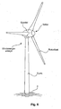
- a modern wind turbine has a nacelle with an aerodynamic rotor.
- the gondola is carried on a tower and the tower is anchored in and supported by a foundation.
- FIG. 6 shows such a wind turbine.
- towers of wind turbines can reach a height of over 100 m.
- the diameter of the aerodynamic rotor can also reach a diameter of over 100 m.
- Towers of such wind turbines are usually made of steel and / or prestressed concrete and have an enormous weight.
- the weight of the nacelle which in the case of a gearless wind turbine can have a generator of 10 m diameter or even more and a corresponding weight which must be borne by the foundation in addition to the tare weight of the tower.
- an enormous wind pressure on the aerodynamic rotor which is ultimately passed over the tower in the foundation and there can lead to a tipping moment.
- a steel section which can also be referred to as anchoring section, partially embedded in the foundation, so in the concrete of the foundation to attach the tower on this anchoring section.
- anchoring section partially embedded in the foundation, so in the concrete of the foundation to attach the tower on this anchoring section.
- this anchoring section thus a lowermost tower section of a tower is attached.
- Such an anchoring section can basically be configured as a T-beam bent into a circle, which is concreted in over the head in relation to the letter T.
- the anchoring section thus has, when properly anchored at its lowermost end a horizontal, circumferential flange portion (which gives the T-beam its name) and over which the loads occurring are introduced into the foundation. Part of this anchoring section then projects beyond a surface of the foundation, ie beyond a concrete surface.
- This surface-projecting portion may have, for receiving loads, a further circumferential portion, in particular a flange portion, for securing thereto said lower tower section.
- a problem with this embodiment of an anchoring is that in particular the load application via the lower, horizontal circumferential flange can lead to damage to the foundation.
- the anchoring section pushes a lying below the lower flange portion of the concrete foundation in the worst case funnel shape, or that at least corresponding fractures, fracture areas or crack areas occur in the foundation.
- it is particularly problematic that such damage occurs in the lower region of the foundation and therefore can be difficult to detect.
- in the event of cracking there is the problem that water can penetrate into the crack and thus into the foundation and reinforce the damage to the foundation.
- German Patent and Trademark Office has researched the following prior art in the priority application: DE 20 2010 005 965 U1 . WO 2008/087181 A1 . DE 102 26 996 A1 . WO 2011/029994 A1 and DE 25 44 657 A1 ,
- the present invention is therefore based on the object to improve the anchoring of a tower of a wind turbine and possibly avoid or reduce the above-mentioned problems.
- a solution is proposed which leads to improved anchoring and avoids damage to the foundation.
- At least an alternative solution should be proposed.
- an anchoring section according to claim 1 is proposed.
- Such an anchoring section is provided for anchoring a tower of a wind turbine in a foundation. It comprises a support section and a foundation section.
- the support section is prepared for attaching a tower segment for supporting the tower. For example, it may have a circumferential flange for placing a tower section and with holes for passing fastening screws.
- the support section is arranged as intended above the foundation.
- the foundation section is intended for concreting in the foundation, ie in a corresponding concrete mass of the foundation.
- the foundation section has at least one web section, which is at least partially embedded in the foundation.
- the web portion is provided with through holes through which reinforcing bars or similar elements of a reinforcement of the foundation can be performed.
- These passage openings can, for example, be circular in shape and are intended to at least partially absorb concrete during setting in concrete and can thereby derive vertical forces into the foundation. This can be reinforced by reinforcing bars arranged in the openings.
- the passage openings are arranged in a plurality, namely at least 2, 3, 4 or more than 4, in particular horizontal, rows.
- the load transfer can hereby be distributed quite evenly, as a result of which local load maxima, in particular directly below the anchoring section, namely below the foundation section of the anchoring section, are avoided. This is to prevent damage caused by local maximum load.
- through openings are thus arranged at different heights, that is, different vertical positions in the web portion.
- Each of these passage openings guided a reinforcing bar and, accordingly, the load transfer from the web portion into the reinforcement in different levels of the foundation can be done.
- a uniform distribution of the passage openings in the respective rows of openings is to be preferred, in order to ensure the most even possible load transfer. Nevertheless, other distributions can also be considered in principle.
- the web portion is formed as a cylinder jacket.
- only one segment of a cylinder jacket can be provided in such a form or another form, for example, to assemble several segments to form a completely circumferential cylinder jacket.
- the web portion may be slightly inclined relative to the direction of rotation of the web portion, based on a vertical sectional view, resulting in a shape of a truncated cone shell.
- the use of a thus circular shape - in a plan view of the anchoring section - is the preferred embodiment. This circular shape is so far essentially conditioned by the shape of the aufdin lower tower segment.
- the support section is designed as a flange.
- the support portion is advantageously designed as a flange in the sense of a mounting flange.
- an anchoring section or the like which would also be formed as a flange, is avoided on the side remote from the support section on the web section.
- a load is then carried out exclusively or substantially through the through holes, possibly supported by guided through them reinforcement. Bundling of the load entry via other anchoring sections is avoided.
- the anchoring section is a steel section. This is thus adapted to the connection with a lower tower section made of steel - with or without compensation.
- a further preferred embodiment proposes that the passage openings are each formed substantially oval and / or elliptical and have a vertical orientation as intended. When properly anchored, the through holes thus have a greater extent in the vertical direction than in the horizontal direction. This can be done by a substantially elliptical or oval shape. In principle, rectangular or polygonal shapes are also considered.
- the passage opening preferably has a mean diameter of more than 80 mm, preferably more than 100 mm and in particular more than 110 mm. This size ensures that a reinforcement or a reinforcing bar can be well guided through the through hole and still has room for the concrete mass. For this purpose, it is assumed that a reinforcing steel, which has a diameter of about 25 mm, possibly less. There then remains enough space for concrete containing gravel with a grain size of at most 32 mm average diameter, in particular for grain sizes of about 32 mm average diameter, which is preferably proposed for use.
- Oval or elliptical through holes have a small and a large diameter, the small diameter is in the range of 50-90 mm, in particular 60-80 mm, and the large diameter in the range of 90-130mm, in particular from 100 to 110 mm. In this way, a favorable load entry can be achieved by means of the through holes.
- the through holes are lined with an elastic and / or resilient material, in particular an artificial foam.
- an elastic and / or resilient material in particular an artificial foam.
- a substructure of a wind turbine for anchoring a tower of the wind turbine, which proposes a concrete foundation with an anchoring section according to the invention.
- Such a substructure thus essentially comprises the steel reinforced concrete foundation with steel reinforcement and an anchoring section. Bars of reinforcement of this reinforced concrete are made, at least in part, through through holes of the anchoring section to thereby achieve or at least improve load transfer from the anchoring section via the reinforcement into the foundation.
- Such a substructure of foundation and anchoring section promises to be stable and durable and to ensure the most uniform possible load transfer in order to form a stable substructure for a tower of a wind turbine accordingly.
- the substructure is designed so that the support portion, in particular a circumferential horizontal mounting flange, is spaced from the concrete foundation.
- the support portion in particular a circumferential horizontal mounting flange
- a solid surface of the concrete foundation consisting essentially of concrete, results.
- the support portion thus at a distance. This favors in particular the attachment of a lower tower section on the anchoring section.
- the substructure according to a further embodiment is characterized in that sections of the reinforcement, in particular reinforcing bars, which extend through the through openings are surrounded in the passage opening by a filling material, in particular concrete, so that a contact of these sections with the through openings is avoided.
- the filler material prevents direct contact between reinforcing bars and the anchoring section. As a result, local load maximums are avoided, which could occur if a direct connection and thus direct power transmission of the foundation section of the anchoring section would take place on a reinforcing rod. Incidentally, it may also be advantageous for galvanic reasons, ie to avoid a galvanic connection between the anchoring section and the reinforcement, to avoid this direct contact. A load transfer then takes place indirectly from the anchoring section via the filling material to the respective reinforcing bar.
- a compressible, in particular elastic material is preferably arranged below the anchoring section.
- a foam material and / or plastic material as a compressible material, to name only two examples.
- a wind turbine with a tower in which the tower by means of an anchoring section according to the invention and on a substructure such anchored above.
- Such a wind turbine thus has a foundation, in which an anchoring section is anchored, on which the tower of the wind turbine is attached.
- a method for anchoring a tower of a wind turbine comprises at least the steps of preparing a reinforcement of a concrete foundation of a wind turbine, together with an anchoring section for anchoring the tower in the concrete foundation, wherein sections of the reinforcement, in particular reinforcing bars, are guided through through openings in a web section of the anchoring section at different heights, and pouring and hardening the concrete foundation to anchor the anchoring section in the concrete foundation.
- a reinforcement of a concrete foundation of a wind turbine is prepared together with an anchoring section. It is thus prepared in a pit in which the foundation is to sit later, a braid of reinforcement.
- the anchoring section is positioned.
- the anchoring section has through holes and the reinforcement is prepared together with the anchoring section so that reinforcing bars of the reinforcement pass through the through holes of the anchoring section.
- the concrete mass is poured into a formwork arranged in the excavation and encloses the reinforcement completely and the anchoring section partially, namely in the area of your foundation section and thus also in the area of the through openings. Finally, the concrete mass must harden.
- FIG. 1 shows a basically known anchoring section 101 in a side sectional view and the anchoring section 101 is partially embedded in a concrete foundation 102.
- the concrete foundation 102 is not shown hatched for reasons of clarity.
- the anchoring section has a largely concreted web section 104, which has an approximately horizontally formed flange section 106 as an anchoring section on its underside.
- a mounting flange 108 is provided to which a lower tower section can be attached.
- the anchoring section 101 also has a further support flange 110 which can be supported on a plane 112 shown by way of example in order to introduce pressure forces into the foundation 102.
- the support flange 110 can - as shown - also be poured into the concrete foundation 102 and has from its upper edge still a distance of, for example 20 cm up to an upper edge 114 of the concrete, ie concrete foundations, on. Alternatively, the support flange 110 rests directly on a concrete top, so that the plane 112 shown then indicates the upper edge of the concrete and the upper edge 114 is omitted.
- Loads on the anchoring section 101 that act in a substantially vertical direction are primarily introduced into the concrete foundation 102 via the anchoring section 106 and the support flange 110. This is what happens in these areas the anchoring portion 106 and the support flange 110 to local load maxima.
- a downwardly acting load - the pressure D - on the anchoring portion 106 may be diverted therefrom into the concrete foundation 102 so as to exert a force approximately funnel-shaped from the anchoring portion 106 into the lower portion of the concrete foundation 102.
- a funnel-shaped portion 116 breaks out of the foundation or at least at its edges defects, fractures or cracks may form.
- Such potential damage areas 118 are in the FIG. 1 dashed lines for clarity.
- tensile loads acting on the anchoring section 101 may result in similar local loading maxima and similar damage and cause fractures or cracks above the support flange.
- FIG. 2 Another anchoring section 101 according to. FIG. 2 has a web portion 104 with an anchoring portion 106 and a mounting flange 108.
- the web portion 104 is partially and the anchoring portion 106 completely embedded in a concrete foundation 102.
- the mounting flange 108 and a part of the web portion 104 projects beyond the upper edge 114 of the concrete foundation 102.
- the FIG. 2 also shows a passage opening 120, through which a reinforcing bar 122 is passed.
- the reinforcing bar 122 is part of a reinforcement of the concrete foundation 102, which in the FIG. 2 not shown.
- the reinforcing bar 122 is intended to receive horizontal forces.
- a part of the corresponding load can be transmitted to the reinforcing bar 122 by undesired load introduction, which here represents a plurality of reinforcing bars, which are not shown in this sectional view.
- a resulting load is introduced into the concrete foundation 102 via the reinforcing bar.
- the reinforcing bar 122 bends due to undesirable vertical load application and leads to loads on the concrete.
- the dashed line 124 illustrates such a bent reinforcing bar in an exaggerated representation. Thus, damage to the concrete on its upper side can also occur as a result.
- a portion of the load from the anchoring portion 106 is introduced upwardly into the concrete foundation 102.
- a such introduction of a force from the anchoring portion 106 is in the FIG. 2 illustrated by a load path 126. This begins at an upper side of the anchoring portion 106 and extends from there dashed to the reinforcement - the reinforcing bar 122 - and from there back in the vertical direction down to the foundation. This results in some diagonal force directions, in some of which concentrated forces act, which can lead to an unfavorable stress concentration.
- FIG. 3 illustrates the basic structure of an anchoring section 1 according to an embodiment.
- the anchoring section 1 of FIG. 3 has a mounting flange 8 with a plurality of mounting holes 30.
- a web section 4 is substantially concreted into a concrete foundation 2, the upper edge 14 of which is indicated by way of illustration.
- the concreted section of the web section 4 has a multiplicity of passage openings 20, through which a reinforcing bar 22 is guided.
- the reinforcing bar 22 may also be referred to as push-through reinforcement and consists of reinforcing steel.
- FIG. 3 are only shown in some through holes 20, which can also be referred to as bores, rebars 22 carried out as performed.
- embodiments may be designed so that a reinforcement bar or similar or comparable element of a reinforcement is performed through each passage opening.
- the passage openings 20 according to FIG. 3 are arranged in a plurality of horizontally extending rows, namely according to the embodiment shown in three rows. At the same time a substantially uniform distribution of the through holes is also favored provided by the row-wise arrangement. As a result, a possible uniformly distributed load entry from the anchoring section 1 through the through holes and possibly or partially on the reinforcing bars 22 in the foundation 2 are made possible.
- the plurality of distributed passage openings correspondingly allows the distribution of the load input, thereby distributing the load in the foundation and avoid stress concentrations, in particular resulting damage.
- FIG. 4 shows an enlargement of a through hole 20 with carried rebar 22 schematically.
- This enlargement illustrates that the reinforcing bar 22 should be positioned in the passage opening 20 of the web section 4 such that the web section 4 and thus a boundary of the passage opening 20 is not touched.
- the reinforcing bar 22 is surrounded in the passage opening 20 with a filling material 28. Forces, including shear forces, can thus be absorbed by the reinforcing bar 22 from the web section 4 and thus the anchoring section 1. In this case, a force is transmitted from the web portion 4 only indirectly via the filler or intermediate material on the reinforcing rod.
- FIG. 5 shows an embodiment of a through hole 20 in a detailed view.
- the passage opening 20 thus essentially has an oval shape, the longitudinal direction of which extends in the vertical direction when the anchoring section is used as intended.
- a reinforcing bar 22 is shown in cross-section, which is surrounded by a filling material 28. Due to the substantially oval shape of the passage opening 20 significantly more filling material above and below the reinforcing bar 22 is arranged as the side of him. It should be noted that this schematic representation for better representation of the proportions does not reflect correctly. In particular, in a scale representation of the diameter of the reinforcing rod would be much smaller than he in FIG. 5 is shown.
- a solution which relates in particular to an anchoring section for partial encasing in a reinforced concrete foundation.
- the solution makes possible an efficient and as even as possible transfer of force from the anchoring section into the foundation.
- Load transfer thus takes place from the web section via the filler material to the reinforcing bar and further into the foundation, and / or directly from the web section in the area of the through openings into the foundation.
- the filling material that surrounds the reinforcing rod thus and can be made of concrete, can therefore also be referred to as concrete dowels.
- a compressible, in particular elastic material 300 is preferably arranged below the anchoring section 1.
- compressible material 300 a foam material and / or plastic material, to name just two examples.
Landscapes
- Engineering & Computer Science (AREA)
- General Engineering & Computer Science (AREA)
- Life Sciences & Earth Sciences (AREA)
- General Life Sciences & Earth Sciences (AREA)
- Chemical & Material Sciences (AREA)
- Combustion & Propulsion (AREA)
- Mechanical Engineering (AREA)
- Sustainable Energy (AREA)
- Sustainable Development (AREA)
- Mining & Mineral Resources (AREA)
- Paleontology (AREA)
- Civil Engineering (AREA)
- Structural Engineering (AREA)
- Foundations (AREA)
- Wind Motors (AREA)
- Artificial Fish Reefs (AREA)
Priority Applications (2)
| Application Number | Priority Date | Filing Date | Title |
|---|---|---|---|
| MEP-2016-252A ME02550B (me) | 2011-11-24 | 2012-11-16 | Uređaj i postupak za sidrenje vjetroturbine |
| PL12797789T PL2783111T3 (pl) | 2011-11-24 | 2012-11-16 | Urządzenie i sposób do kotwienia elektrowni wiatrowej |
Applications Claiming Priority (2)
| Application Number | Priority Date | Filing Date | Title |
|---|---|---|---|
| DE102011087022A DE102011087022A1 (de) | 2011-11-24 | 2011-11-24 | Vorrichtung und Verfahren zum Verankern einer Windenergieanlage |
| PCT/EP2012/072922 WO2013076021A1 (de) | 2011-11-24 | 2012-11-16 | Vorrichtung und verfahren zum verankern einer windenergieanlage |
Publications (2)
| Publication Number | Publication Date |
|---|---|
| EP2783111A1 EP2783111A1 (de) | 2014-10-01 |
| EP2783111B1 true EP2783111B1 (de) | 2016-10-26 |
Family
ID=47297163
Family Applications (1)
| Application Number | Title | Priority Date | Filing Date |
|---|---|---|---|
| EP12797789.0A Active EP2783111B1 (de) | 2011-11-24 | 2012-11-16 | Vorrichtung und verfahren zum verankern einer windenergieanlage |
Country Status (20)
| Country | Link |
|---|---|
| US (1) | US9790925B2 (pl) |
| EP (1) | EP2783111B1 (pl) |
| JP (1) | JP2014534376A (pl) |
| KR (1) | KR20140097320A (pl) |
| CN (1) | CN103958892B (pl) |
| AR (1) | AR088965A1 (pl) |
| BR (1) | BR112014012329A2 (pl) |
| CA (1) | CA2854567C (pl) |
| CL (1) | CL2014001326A1 (pl) |
| DE (1) | DE102011087022A1 (pl) |
| DK (1) | DK2783111T3 (pl) |
| ES (1) | ES2608594T3 (pl) |
| ME (1) | ME02550B (pl) |
| MX (1) | MX345985B (pl) |
| PL (1) | PL2783111T3 (pl) |
| PT (1) | PT2783111T (pl) |
| RU (1) | RU2594841C2 (pl) |
| TW (1) | TWI506201B (pl) |
| WO (1) | WO2013076021A1 (pl) |
| ZA (1) | ZA201403139B (pl) |
Families Citing this family (8)
| Publication number | Priority date | Publication date | Assignee | Title |
|---|---|---|---|---|
| DE102013211750A1 (de) * | 2013-06-21 | 2014-12-24 | Wobben Properties Gmbh | Windenergieanlage und Windenergieanlagen-Fundament |
| US9783950B2 (en) * | 2014-10-07 | 2017-10-10 | Allan P. Henderson | Retrofit reinforcing structure addition and method for wind turbine concrete gravity spread foundations and the like |
| ES2589962B1 (es) * | 2015-04-17 | 2017-09-08 | Gamesa Innovation & Technology, S.L. | Dispositivo de unión de un tramo metálico con un tramo de hormigón en una torre hueca híbrida |
| AT517958B1 (de) * | 2016-02-18 | 2017-06-15 | Holcim Technology Ltd | Fundament für ein Windrad |
| AT517959B1 (de) * | 2016-02-18 | 2017-06-15 | Holcim Technology Ltd | Fundament für ein Windrad |
| WO2019077382A1 (en) * | 2017-10-18 | 2019-04-25 | Terre Armee Internationale | REUSABLE CASTING ELEMENT FOR A FACING ELEMENT AND METHOD FOR MANUFACTURING A FACING ELEMENT USING SAID REUSABLE CASTING ELEMENT |
| EP3807532B1 (en) * | 2018-06-14 | 2023-07-19 | Vestas Wind Systems A/S | Wind turbine powertrain connection |
| CN111979894A (zh) * | 2020-08-14 | 2020-11-24 | 上海市政工程设计研究总院(集团)有限公司 | 一种钢立柱与混凝土承台连接结构及其施工方法 |
Citations (1)
| Publication number | Priority date | Publication date | Assignee | Title |
|---|---|---|---|---|
| US20100005742A1 (en) * | 2007-01-18 | 2010-01-14 | Ecotecnia Energias Renovables, S.L. | Joining device for hybrid wind turbine towers |
Family Cites Families (24)
| Publication number | Priority date | Publication date | Assignee | Title |
|---|---|---|---|---|
| US723669A (en) * | 1902-07-15 | 1903-03-24 | William Hammann | Anchor for railing-posts. |
| US2625815A (en) * | 1943-10-23 | 1953-01-20 | Eric A Black | Adjustable anchorage |
| CH586799A5 (pl) * | 1974-10-17 | 1977-04-15 | Walther Rene Fa | |
| US4272929A (en) * | 1979-08-23 | 1981-06-16 | Hanson Bror H | Tower and method of construction |
| FR2601398B3 (fr) * | 1986-07-10 | 1988-12-02 | Dumesnil Odile | Dispositif d'ancrage d'elements tels que barrieres, poteaux sur des ouvrages en beton. |
| JPS63181816A (ja) * | 1987-01-19 | 1988-07-27 | Takenaka Komuten Co Ltd | 地中梁構成材 |
| JPH0723629B2 (ja) * | 1988-06-21 | 1995-03-15 | クボタハウス株式会社 | 基礎天化粧水切の取付け方法とその装置 |
| US4926061A (en) * | 1988-08-08 | 1990-05-15 | Ecm International Inc. | Windtrap energy system |
| JP2860490B2 (ja) * | 1989-12-27 | 1999-02-24 | 積水ハウス株式会社 | 建築物の鉄骨基礎 |
| US5218803A (en) * | 1991-11-04 | 1993-06-15 | Wright Jeff A | Method and means for reinforcing a steel stud wall |
| RU2070662C1 (ru) * | 1994-04-13 | 1996-12-20 | Валентин Александрович Харитонов | Устройство ветроэнергетической установки |
| WO2000046451A1 (fr) * | 1999-02-03 | 2000-08-10 | Nippon Pillar Packing Co., Ltd. | Fondations servant d'infrastructures sur pieux |
| CA2424334C (en) * | 2000-09-27 | 2008-07-22 | Allan P. Henderson | Perimeter weighted foundation for wind turbines and the like |
| DE10226996B4 (de) * | 2001-10-09 | 2014-07-03 | Aloys Wobben | Verfahren zur Erstellung eines Fundaments, insbesondere für einen Turm einer Windenergieanlage |
| ES2280852T3 (es) * | 2003-08-09 | 2007-09-16 | General Electric Company | Cimiento para torre, en particular para una turbina de energia eolica. |
| US7513083B2 (en) * | 2004-08-17 | 2009-04-07 | Simpson Strong-Tie Company, Inc. | Rotating concentric holdown |
| US7627995B1 (en) * | 2007-02-12 | 2009-12-08 | Yoder Jason L | Post frame building bracket and method of use |
| JP4523662B1 (ja) * | 2009-03-31 | 2010-08-11 | 三井造船株式会社 | 塔状構造物の基礎構造 |
| EP2427603B1 (en) * | 2009-05-05 | 2018-03-14 | Ahmed Phuly Engineering & Consulting, Inc. | Fatigue resistant foundation |
| FI20095942A7 (fi) * | 2009-09-11 | 2011-03-12 | Peikko Group Oy | Liitoselin tornirakenteen säteittäistä raudoitusrakennetta varten ja säteittäinen raudoitusrakenne tornirakennetta varten |
| DE202010005965U1 (de) * | 2010-04-21 | 2011-08-29 | Rosen Swiss Ag | Hülse, Fundament und Windkraftanlage |
| DE102010028038B4 (de) * | 2010-04-21 | 2015-02-05 | Wobben Properties Gmbh | Windenergieanlagen-Fundament und Windenergieanlage |
| US9783950B2 (en) * | 2014-10-07 | 2017-10-10 | Allan P. Henderson | Retrofit reinforcing structure addition and method for wind turbine concrete gravity spread foundations and the like |
| DE202015100932U1 (de) * | 2015-02-26 | 2015-06-10 | Wpt Nord Gmbh | Vorrichtung zum Sichern, insbesondere Sanieren, eines Fundaments bei Windenergieanlagen, sowie Fundament |
-
2011
- 2011-11-24 DE DE102011087022A patent/DE102011087022A1/de not_active Withdrawn
-
2012
- 2012-11-16 PL PL12797789T patent/PL2783111T3/pl unknown
- 2012-11-16 CN CN201280058069.9A patent/CN103958892B/zh active Active
- 2012-11-16 BR BR112014012329A patent/BR112014012329A2/pt active Search and Examination
- 2012-11-16 DK DK12797789.0T patent/DK2783111T3/en active
- 2012-11-16 KR KR1020147015436A patent/KR20140097320A/ko not_active Ceased
- 2012-11-16 RU RU2014125424/06A patent/RU2594841C2/ru not_active IP Right Cessation
- 2012-11-16 PT PT127977890T patent/PT2783111T/pt unknown
- 2012-11-16 WO PCT/EP2012/072922 patent/WO2013076021A1/de not_active Ceased
- 2012-11-16 ME MEP-2016-252A patent/ME02550B/me unknown
- 2012-11-16 US US14/359,896 patent/US9790925B2/en active Active
- 2012-11-16 MX MX2014005922A patent/MX345985B/es active IP Right Grant
- 2012-11-16 EP EP12797789.0A patent/EP2783111B1/de active Active
- 2012-11-16 ES ES12797789.0T patent/ES2608594T3/es active Active
- 2012-11-16 CA CA2854567A patent/CA2854567C/en not_active Expired - Fee Related
- 2012-11-16 JP JP2014542780A patent/JP2014534376A/ja active Pending
- 2012-11-23 TW TW101144054A patent/TWI506201B/zh not_active IP Right Cessation
- 2012-11-23 AR ARP120104405A patent/AR088965A1/es active IP Right Grant
-
2014
- 2014-04-30 ZA ZA2014/03139A patent/ZA201403139B/en unknown
- 2014-05-20 CL CL2014001326A patent/CL2014001326A1/es unknown
Patent Citations (1)
| Publication number | Priority date | Publication date | Assignee | Title |
|---|---|---|---|---|
| US20100005742A1 (en) * | 2007-01-18 | 2010-01-14 | Ecotecnia Energias Renovables, S.L. | Joining device for hybrid wind turbine towers |
Also Published As
| Publication number | Publication date |
|---|---|
| US20140348663A1 (en) | 2014-11-27 |
| TW201341652A (zh) | 2013-10-16 |
| MX2014005922A (es) | 2014-06-19 |
| CA2854567A1 (en) | 2013-05-30 |
| JP2014534376A (ja) | 2014-12-18 |
| DE102011087022A1 (de) | 2013-05-29 |
| ME02550B (me) | 2017-02-20 |
| MX345985B (es) | 2017-03-01 |
| ES2608594T3 (es) | 2017-04-12 |
| RU2014125424A (ru) | 2015-12-27 |
| ZA201403139B (en) | 2015-04-29 |
| NZ624575A (en) | 2016-04-29 |
| AU2012342674A1 (en) | 2014-05-29 |
| AR088965A1 (es) | 2014-07-23 |
| KR20140097320A (ko) | 2014-08-06 |
| CN103958892B (zh) | 2017-05-24 |
| CL2014001326A1 (es) | 2014-11-21 |
| RU2594841C2 (ru) | 2016-08-20 |
| CN103958892A (zh) | 2014-07-30 |
| DK2783111T3 (en) | 2017-01-30 |
| PT2783111T (pt) | 2017-01-18 |
| EP2783111A1 (de) | 2014-10-01 |
| WO2013076021A1 (de) | 2013-05-30 |
| TWI506201B (zh) | 2015-11-01 |
| BR112014012329A2 (pt) | 2017-05-30 |
| US9790925B2 (en) | 2017-10-17 |
| PL2783111T3 (pl) | 2017-05-31 |
| CA2854567C (en) | 2017-09-12 |
Similar Documents
| Publication | Publication Date | Title |
|---|---|---|
| EP2783111B1 (de) | Vorrichtung und verfahren zum verankern einer windenergieanlage | |
| EP2776637B1 (de) | Fundament einer windenergieanlage | |
| EP3821083B1 (de) | Fundament für ein windkraftwerk | |
| EP3662122B1 (de) | Fundament für ein bauwerk | |
| AT517958B1 (de) | Fundament für ein Windrad | |
| EP3821084B1 (de) | Fundament für ein windkraftwerk | |
| AT517959B1 (de) | Fundament für ein Windrad | |
| EP2009202A2 (de) | Windenergieanlagenturm | |
| EP1786990B1 (de) | Stahlbeton-hohlkörperplatte oder -decke | |
| EP2931977B1 (de) | Verfahren zur verankerung einer gründungsstruktur und gründungsstruktur | |
| EP3011175B1 (de) | Windenergieanlagen-fundament | |
| EP3341528B1 (de) | Windenergieanlage | |
| EP1248889B1 (de) | Deckenverstärkung und verfahren zu ihrer herstellung | |
| EP3891386B1 (de) | Verfahren zum vorspannen eines turms einer windenergieanlage | |
| DE102021100799B4 (de) | Turm für eine Windenergieanlage sowie Adapter | |
| EP3597829B1 (de) | Gründungsverstärkung für offshore-bauwerke | |
| EP3768898B1 (de) | Halbfertigteil für ein fundament eines turmbauwerks, halbfertigteil-fundamentsegment, fundament, verfahren zum herstellen eines halbfertigteils sowie verfahren zum herstellen eines fundaments | |
| EP3219879A1 (de) | Verfahren zum aufstellen eines windenergieanlagen-turms sowie entsprechende windenergieanlage | |
| EP3149326B1 (de) | Windenergieanlagen-turm und verfahren zum errichten eines windenergieanlagen-turms | |
| DE202013011256U1 (de) | Fundament für eine Windkraftanlage | |
| NZ624575B2 (en) | Device and method for anchoring a wind turbine |
Legal Events
| Date | Code | Title | Description |
|---|---|---|---|
| PUAI | Public reference made under article 153(3) epc to a published international application that has entered the european phase |
Free format text: ORIGINAL CODE: 0009012 |
|
| 17P | Request for examination filed |
Effective date: 20140624 |
|
| AK | Designated contracting states |
Kind code of ref document: A1 Designated state(s): AL AT BE BG CH CY CZ DE DK EE ES FI FR GB GR HR HU IE IS IT LI LT LU LV MC MK MT NL NO PL PT RO RS SE SI SK SM TR |
|
| AX | Request for extension of the european patent |
Extension state: BA ME |
|
| RAP1 | Party data changed (applicant data changed or rights of an application transferred) |
Owner name: WOBBEN PROPERTIES GMBH |
|
| GRAP | Despatch of communication of intention to grant a patent |
Free format text: ORIGINAL CODE: EPIDOSNIGR1 |
|
| REG | Reference to a national code |
Ref country code: DE Ref legal event code: R079 Ref document number: 502012008642 Country of ref document: DE Free format text: PREVIOUS MAIN CLASS: F03D0011040000 Ipc: F03D0013200000 |
|
| INTG | Intention to grant announced |
Effective date: 20160509 |
|
| RIC1 | Information provided on ipc code assigned before grant |
Ipc: F03D 13/20 20160101AFI20160510BHEP Ipc: E02D 27/42 20060101ALI20160510BHEP |
|
| GRAJ | Information related to disapproval of communication of intention to grant by the applicant or resumption of examination proceedings by the epo deleted |
Free format text: ORIGINAL CODE: EPIDOSDIGR1 |
|
| GRAJ | Information related to disapproval of communication of intention to grant by the applicant or resumption of examination proceedings by the epo deleted |
Free format text: ORIGINAL CODE: EPIDOSDIGR1 |
|
| GRAR | Information related to intention to grant a patent recorded |
Free format text: ORIGINAL CODE: EPIDOSNIGR71 |
|
| GRAS | Grant fee paid |
Free format text: ORIGINAL CODE: EPIDOSNIGR3 |
|
| GRAA | (expected) grant |
Free format text: ORIGINAL CODE: 0009210 |
|
| INTC | Intention to grant announced (deleted) | ||
| AK | Designated contracting states |
Kind code of ref document: B1 Designated state(s): AL AT BE BG CH CY CZ DE DK EE ES FI FR GB GR HR HU IE IS IT LI LT LU LV MC MK MT NL NO PL PT RO RS SE SI SK SM TR |
|
| AX | Request for extension of the european patent |
Extension state: BA ME |
|
| INTG | Intention to grant announced |
Effective date: 20160919 |
|
| REG | Reference to a national code |
Ref country code: GB Ref legal event code: FG4D Free format text: NOT ENGLISH |
|
| REG | Reference to a national code |
Ref country code: CH Ref legal event code: EP |
|
| REG | Reference to a national code |
Ref country code: AT Ref legal event code: REF Ref document number: 840220 Country of ref document: AT Kind code of ref document: T Effective date: 20161115 |
|
| REG | Reference to a national code |
Ref country code: IE Ref legal event code: FG4D Free format text: LANGUAGE OF EP DOCUMENT: GERMAN |
|
| REG | Reference to a national code |
Ref country code: FR Ref legal event code: PLFP Year of fee payment: 5 |
|
| REG | Reference to a national code |
Ref country code: DE Ref legal event code: R096 Ref document number: 502012008642 Country of ref document: DE |
|
| REG | Reference to a national code |
Ref country code: PT Ref legal event code: SC4A Ref document number: 2783111 Country of ref document: PT Date of ref document: 20170118 Kind code of ref document: T Free format text: AVAILABILITY OF NATIONAL TRANSLATION Effective date: 20170110 |
|
| REG | Reference to a national code |
Ref country code: DK Ref legal event code: T3 Effective date: 20170127 |
|
| REG | Reference to a national code |
Ref country code: NL Ref legal event code: FP |
|
| REG | Reference to a national code |
Ref country code: SE Ref legal event code: TRGR |
|
| REG | Reference to a national code |
Ref country code: LT Ref legal event code: MG4D |
|
| PG25 | Lapsed in a contracting state [announced via postgrant information from national office to epo] |
Ref country code: LV Free format text: LAPSE BECAUSE OF FAILURE TO SUBMIT A TRANSLATION OF THE DESCRIPTION OR TO PAY THE FEE WITHIN THE PRESCRIBED TIME-LIMIT Effective date: 20161026 |
|
| REG | Reference to a national code |
Ref country code: NO Ref legal event code: T2 Effective date: 20161026 |
|
| REG | Reference to a national code |
Ref country code: EE Ref legal event code: FG4A Ref document number: E013251 Country of ref document: EE Effective date: 20170125 |
|
| REG | Reference to a national code |
Ref country code: ES Ref legal event code: FG2A Ref document number: 2608594 Country of ref document: ES Kind code of ref document: T3 Effective date: 20170412 |
|
| PG25 | Lapsed in a contracting state [announced via postgrant information from national office to epo] |
Ref country code: LT Free format text: LAPSE BECAUSE OF FAILURE TO SUBMIT A TRANSLATION OF THE DESCRIPTION OR TO PAY THE FEE WITHIN THE PRESCRIBED TIME-LIMIT Effective date: 20161026 Ref country code: GR Free format text: LAPSE BECAUSE OF FAILURE TO SUBMIT A TRANSLATION OF THE DESCRIPTION OR TO PAY THE FEE WITHIN THE PRESCRIBED TIME-LIMIT Effective date: 20170127 |
|
| PG25 | Lapsed in a contracting state [announced via postgrant information from national office to epo] |
Ref country code: RS Free format text: LAPSE BECAUSE OF FAILURE TO SUBMIT A TRANSLATION OF THE DESCRIPTION OR TO PAY THE FEE WITHIN THE PRESCRIBED TIME-LIMIT Effective date: 20161026 Ref country code: FI Free format text: LAPSE BECAUSE OF FAILURE TO SUBMIT A TRANSLATION OF THE DESCRIPTION OR TO PAY THE FEE WITHIN THE PRESCRIBED TIME-LIMIT Effective date: 20161026 Ref country code: HR Free format text: LAPSE BECAUSE OF FAILURE TO SUBMIT A TRANSLATION OF THE DESCRIPTION OR TO PAY THE FEE WITHIN THE PRESCRIBED TIME-LIMIT Effective date: 20161026 Ref country code: IS Free format text: LAPSE BECAUSE OF FAILURE TO SUBMIT A TRANSLATION OF THE DESCRIPTION OR TO PAY THE FEE WITHIN THE PRESCRIBED TIME-LIMIT Effective date: 20170226 |
|
| REG | Reference to a national code |
Ref country code: CH Ref legal event code: PL |
|
| REG | Reference to a national code |
Ref country code: DE Ref legal event code: R097 Ref document number: 502012008642 Country of ref document: DE |
|
| PG25 | Lapsed in a contracting state [announced via postgrant information from national office to epo] |
Ref country code: SK Free format text: LAPSE BECAUSE OF FAILURE TO SUBMIT A TRANSLATION OF THE DESCRIPTION OR TO PAY THE FEE WITHIN THE PRESCRIBED TIME-LIMIT Effective date: 20161026 Ref country code: CZ Free format text: LAPSE BECAUSE OF FAILURE TO SUBMIT A TRANSLATION OF THE DESCRIPTION OR TO PAY THE FEE WITHIN THE PRESCRIBED TIME-LIMIT Effective date: 20161026 Ref country code: CH Free format text: LAPSE BECAUSE OF NON-PAYMENT OF DUE FEES Effective date: 20161130 Ref country code: LI Free format text: LAPSE BECAUSE OF NON-PAYMENT OF DUE FEES Effective date: 20161130 Ref country code: MC Free format text: LAPSE BECAUSE OF FAILURE TO SUBMIT A TRANSLATION OF THE DESCRIPTION OR TO PAY THE FEE WITHIN THE PRESCRIBED TIME-LIMIT Effective date: 20161026 Ref country code: RO Free format text: LAPSE BECAUSE OF FAILURE TO SUBMIT A TRANSLATION OF THE DESCRIPTION OR TO PAY THE FEE WITHIN THE PRESCRIBED TIME-LIMIT Effective date: 20161026 |
|
| PG25 | Lapsed in a contracting state [announced via postgrant information from national office to epo] |
Ref country code: BG Free format text: LAPSE BECAUSE OF FAILURE TO SUBMIT A TRANSLATION OF THE DESCRIPTION OR TO PAY THE FEE WITHIN THE PRESCRIBED TIME-LIMIT Effective date: 20170126 Ref country code: SM Free format text: LAPSE BECAUSE OF FAILURE TO SUBMIT A TRANSLATION OF THE DESCRIPTION OR TO PAY THE FEE WITHIN THE PRESCRIBED TIME-LIMIT Effective date: 20161026 |
|
| PLBE | No opposition filed within time limit |
Free format text: ORIGINAL CODE: 0009261 |
|
| STAA | Information on the status of an ep patent application or granted ep patent |
Free format text: STATUS: NO OPPOSITION FILED WITHIN TIME LIMIT |
|
| PG25 | Lapsed in a contracting state [announced via postgrant information from national office to epo] |
Ref country code: LU Free format text: LAPSE BECAUSE OF NON-PAYMENT OF DUE FEES Effective date: 20161130 |
|
| 26N | No opposition filed |
Effective date: 20170727 |
|
| REG | Reference to a national code |
Ref country code: FR Ref legal event code: PLFP Year of fee payment: 6 |
|
| PG25 | Lapsed in a contracting state [announced via postgrant information from national office to epo] |
Ref country code: SI Free format text: LAPSE BECAUSE OF FAILURE TO SUBMIT A TRANSLATION OF THE DESCRIPTION OR TO PAY THE FEE WITHIN THE PRESCRIBED TIME-LIMIT Effective date: 20161026 |
|
| PG25 | Lapsed in a contracting state [announced via postgrant information from national office to epo] |
Ref country code: HU Free format text: LAPSE BECAUSE OF FAILURE TO SUBMIT A TRANSLATION OF THE DESCRIPTION OR TO PAY THE FEE WITHIN THE PRESCRIBED TIME-LIMIT; INVALID AB INITIO Effective date: 20121116 |
|
| PG25 | Lapsed in a contracting state [announced via postgrant information from national office to epo] |
Ref country code: CY Free format text: LAPSE BECAUSE OF FAILURE TO SUBMIT A TRANSLATION OF THE DESCRIPTION OR TO PAY THE FEE WITHIN THE PRESCRIBED TIME-LIMIT Effective date: 20161026 Ref country code: MK Free format text: LAPSE BECAUSE OF FAILURE TO SUBMIT A TRANSLATION OF THE DESCRIPTION OR TO PAY THE FEE WITHIN THE PRESCRIBED TIME-LIMIT Effective date: 20161026 |
|
| PG25 | Lapsed in a contracting state [announced via postgrant information from national office to epo] |
Ref country code: MT Free format text: LAPSE BECAUSE OF FAILURE TO SUBMIT A TRANSLATION OF THE DESCRIPTION OR TO PAY THE FEE WITHIN THE PRESCRIBED TIME-LIMIT Effective date: 20161026 |
|
| PGFP | Annual fee paid to national office [announced via postgrant information from national office to epo] |
Ref country code: IE Payment date: 20191120 Year of fee payment: 8 Ref country code: NO Payment date: 20191121 Year of fee payment: 8 Ref country code: SE Payment date: 20191125 Year of fee payment: 8 Ref country code: PT Payment date: 20191112 Year of fee payment: 8 |
|
| PGFP | Annual fee paid to national office [announced via postgrant information from national office to epo] |
Ref country code: IT Payment date: 20191120 Year of fee payment: 8 Ref country code: PL Payment date: 20191016 Year of fee payment: 8 Ref country code: ES Payment date: 20191216 Year of fee payment: 8 Ref country code: BE Payment date: 20191121 Year of fee payment: 8 Ref country code: EE Payment date: 20191119 Year of fee payment: 8 |
|
| PGFP | Annual fee paid to national office [announced via postgrant information from national office to epo] |
Ref country code: TR Payment date: 20191114 Year of fee payment: 8 Ref country code: AT Payment date: 20191119 Year of fee payment: 8 |
|
| PG25 | Lapsed in a contracting state [announced via postgrant information from national office to epo] |
Ref country code: AL Free format text: LAPSE BECAUSE OF FAILURE TO SUBMIT A TRANSLATION OF THE DESCRIPTION OR TO PAY THE FEE WITHIN THE PRESCRIBED TIME-LIMIT Effective date: 20161026 |
|
| REG | Reference to a national code |
Ref country code: EE Ref legal event code: MM4A Ref document number: E013251 Country of ref document: EE Effective date: 20201130 |
|
| REG | Reference to a national code |
Ref country code: NO Ref legal event code: MMEP |
|
| REG | Reference to a national code |
Ref country code: SE Ref legal event code: EUG |
|
| REG | Reference to a national code |
Ref country code: AT Ref legal event code: MM01 Ref document number: 840220 Country of ref document: AT Kind code of ref document: T Effective date: 20201116 |
|
| PG25 | Lapsed in a contracting state [announced via postgrant information from national office to epo] |
Ref country code: NO Free format text: LAPSE BECAUSE OF NON-PAYMENT OF DUE FEES Effective date: 20201130 Ref country code: EE Free format text: LAPSE BECAUSE OF NON-PAYMENT OF DUE FEES Effective date: 20201130 Ref country code: PT Free format text: LAPSE BECAUSE OF NON-PAYMENT OF DUE FEES Effective date: 20210517 |
|
| REG | Reference to a national code |
Ref country code: BE Ref legal event code: MM Effective date: 20201130 |
|
| PG25 | Lapsed in a contracting state [announced via postgrant information from national office to epo] |
Ref country code: SE Free format text: LAPSE BECAUSE OF NON-PAYMENT OF DUE FEES Effective date: 20201117 Ref country code: AT Free format text: LAPSE BECAUSE OF NON-PAYMENT OF DUE FEES Effective date: 20201116 |
|
| PG25 | Lapsed in a contracting state [announced via postgrant information from national office to epo] |
Ref country code: IE Free format text: LAPSE BECAUSE OF NON-PAYMENT OF DUE FEES Effective date: 20201116 Ref country code: IT Free format text: LAPSE BECAUSE OF NON-PAYMENT OF DUE FEES Effective date: 20201116 |
|
| REG | Reference to a national code |
Ref country code: ES Ref legal event code: FD2A Effective date: 20220202 |
|
| PG25 | Lapsed in a contracting state [announced via postgrant information from national office to epo] |
Ref country code: ES Free format text: LAPSE BECAUSE OF NON-PAYMENT OF DUE FEES Effective date: 20201117 |
|
| PG25 | Lapsed in a contracting state [announced via postgrant information from national office to epo] |
Ref country code: TR Free format text: LAPSE BECAUSE OF NON-PAYMENT OF DUE FEES Effective date: 20201116 |
|
| PG25 | Lapsed in a contracting state [announced via postgrant information from national office to epo] |
Ref country code: BE Free format text: LAPSE BECAUSE OF NON-PAYMENT OF DUE FEES Effective date: 20201130 |
|
| PG25 | Lapsed in a contracting state [announced via postgrant information from national office to epo] |
Ref country code: PL Free format text: LAPSE BECAUSE OF NON-PAYMENT OF DUE FEES Effective date: 20201116 |
|
| PGFP | Annual fee paid to national office [announced via postgrant information from national office to epo] |
Ref country code: NL Payment date: 20251119 Year of fee payment: 14 |
|
| PGFP | Annual fee paid to national office [announced via postgrant information from national office to epo] |
Ref country code: DE Payment date: 20251201 Year of fee payment: 14 |
|
| PGFP | Annual fee paid to national office [announced via postgrant information from national office to epo] |
Ref country code: GB Payment date: 20251120 Year of fee payment: 14 |
|
| PGFP | Annual fee paid to national office [announced via postgrant information from national office to epo] |
Ref country code: DK Payment date: 20251119 Year of fee payment: 14 |
|
| PGFP | Annual fee paid to national office [announced via postgrant information from national office to epo] |
Ref country code: FR Payment date: 20251120 Year of fee payment: 14 |