EP2783155B1 - Dispositif d'éclairage pour véhicule à moteur - Google Patents
Dispositif d'éclairage pour véhicule à moteur Download PDFInfo
- Publication number
- EP2783155B1 EP2783155B1 EP12826659.0A EP12826659A EP2783155B1 EP 2783155 B1 EP2783155 B1 EP 2783155B1 EP 12826659 A EP12826659 A EP 12826659A EP 2783155 B1 EP2783155 B1 EP 2783155B1
- Authority
- EP
- European Patent Office
- Prior art keywords
- light
- lighting device
- lens
- component
- cover
- Prior art date
- Legal status (The legal status is an assumption and is not a legal conclusion. Google has not performed a legal analysis and makes no representation as to the accuracy of the status listed.)
- Active
Links
Images




Classifications
-
- F—MECHANICAL ENGINEERING; LIGHTING; HEATING; WEAPONS; BLASTING
- F21—LIGHTING
- F21V—FUNCTIONAL FEATURES OR DETAILS OF LIGHTING DEVICES OR SYSTEMS THEREOF; STRUCTURAL COMBINATIONS OF LIGHTING DEVICES WITH OTHER ARTICLES, NOT OTHERWISE PROVIDED FOR
- F21V19/00—Fastening of light sources or lamp holders
-
- F—MECHANICAL ENGINEERING; LIGHTING; HEATING; WEAPONS; BLASTING
- F21—LIGHTING
- F21S—NON-PORTABLE LIGHTING DEVICES; SYSTEMS THEREOF; VEHICLE LIGHTING DEVICES SPECIALLY ADAPTED FOR VEHICLE EXTERIORS
- F21S43/00—Signalling devices specially adapted for vehicle exteriors, e.g. brake lamps, direction indicator lights or reversing lights
- F21S43/20—Signalling devices specially adapted for vehicle exteriors, e.g. brake lamps, direction indicator lights or reversing lights characterised by refractors, transparent cover plates, light guides or filters
-
- F—MECHANICAL ENGINEERING; LIGHTING; HEATING; WEAPONS; BLASTING
- F21—LIGHTING
- F21S—NON-PORTABLE LIGHTING DEVICES; SYSTEMS THEREOF; VEHICLE LIGHTING DEVICES SPECIALLY ADAPTED FOR VEHICLE EXTERIORS
- F21S41/00—Illuminating devices specially adapted for vehicle exteriors, e.g. headlamps
- F21S41/10—Illuminating devices specially adapted for vehicle exteriors, e.g. headlamps characterised by the light source
- F21S41/19—Attachment of light sources or lamp holders
-
- F—MECHANICAL ENGINEERING; LIGHTING; HEATING; WEAPONS; BLASTING
- F21—LIGHTING
- F21S—NON-PORTABLE LIGHTING DEVICES; SYSTEMS THEREOF; VEHICLE LIGHTING DEVICES SPECIALLY ADAPTED FOR VEHICLE EXTERIORS
- F21S41/00—Illuminating devices specially adapted for vehicle exteriors, e.g. headlamps
- F21S41/20—Illuminating devices specially adapted for vehicle exteriors, e.g. headlamps characterised by refractors, transparent cover plates, light guides or filters
- F21S41/28—Cover glass
-
- F—MECHANICAL ENGINEERING; LIGHTING; HEATING; WEAPONS; BLASTING
- F21—LIGHTING
- F21S—NON-PORTABLE LIGHTING DEVICES; SYSTEMS THEREOF; VEHICLE LIGHTING DEVICES SPECIALLY ADAPTED FOR VEHICLE EXTERIORS
- F21S43/00—Signalling devices specially adapted for vehicle exteriors, e.g. brake lamps, direction indicator lights or reversing lights
- F21S43/10—Signalling devices specially adapted for vehicle exteriors, e.g. brake lamps, direction indicator lights or reversing lights characterised by the light source
- F21S43/19—Attachment of light sources or lamp holders
-
- F—MECHANICAL ENGINEERING; LIGHTING; HEATING; WEAPONS; BLASTING
- F21—LIGHTING
- F21V—FUNCTIONAL FEATURES OR DETAILS OF LIGHTING DEVICES OR SYSTEMS THEREOF; STRUCTURAL COMBINATIONS OF LIGHTING DEVICES WITH OTHER ARTICLES, NOT OTHERWISE PROVIDED FOR
- F21V5/00—Refractors for light sources
Definitions
- the invention relates to a lighting device for a motor vehicle having the features of the preamble of patent claim 1.
- Illumination devices are known from the general state of the art.
- so-called multi-chamber lighting devices have a plurality of reflector chambers, which are each associated with one or more lamps and a lens which is fixed to the housing and the reflectors together with their associated bulbs outwardly protects against the environment.
- headlights or lights are already known in which the light is not deflected by reflectors to the outside, but is directed directly via corresponding optical devices (eg. Lenses) to the outside.
- a lens within the meaning of the invention may also be understood as meaning a so-called intermediate or additional lens, which may be arranged in the light emission direction in front of a cover plate or between an optional reflector and an outer lens (cover plate).
- the motor vehicle has a tag design (with the lighting switched off) and a so-called night design (with the lighting switched on).
- At least one louver of a radiator grille comprises or is designed as a luminescent device.
- a headlamp 1 in which a light source is attached to brackets which are inserted from the front or from above through a lens into the interior of the headlamp and releasably secured to the lens.
- brackets which are inserted from the front or from above through a lens into the interior of the headlamp and releasably secured to the lens.
- a signal light is known in which bulbs are held on the inside of a lens, the light is first thrown inward on a reflector and then reflected to the outside. In this way, the immediate visibility of the lamps should be prevented.
- the US 2002/0012251 A1 discloses a signal lamp for a motor vehicle, on the inside of the lens disk holders for LEDs are present.
- the LEDs are arranged in an L-shape and should help that other road users can detect a change in direction of the motor vehicle faster.
- EP 1 070 633 A2 discloses a lamp with multiple light sources.
- one of the light sources is arranged on a transparent intermediate plate by means of a spacer.
- US 2009/0175047 A1 discloses an additional module for a motor vehicle light.
- the additional module can be fixed by means of an adhesive tape on the motor vehicle light and know illuminant for at least one light function.
- the present invention is based on the object, a lighting device according to the preamble of claim 1 in such a way that a further scope is opened to the effect lighting equipment on the one hand occupy a high recognition value and on the other hand to be able to dress with required lighting functions.
- the lighting device for a motor vehicle comprises a housing, at least one light source, which at least contributes to the realization of a specific light function and at least one lens.
- the lens at least indirectly serves as a holder for the at least one light source.
- the lens is assigned a further function in addition to the actual function of a protective cover or in addition to optical functions (e.g., light scattering).
- the lens may be configured so that it can receive or support a prefabricatable unit consisting of a holder and light sources.
- the lighting means can be designed, for example, as (halogen) incandescent lamps or semiconductor diodes, in particular as light-emitting diodes (LEDs), etc.
- the at least one held luminous means by the lens can serve either alone for the realization of a specific light function, but it can also be provided that this only contributes to the realization of a specific light function and at another point of the lighting device, a further light source is provided, which also for the realization the specific light function, such as a daytime running light, is provided.
- the at least one lighting means is held on or in at least one component which is connected to the lens.
- a component can be manufactured separately from the lens and designed as well as technically independent of this. So it is conceivable to use an unchanged "basic lens" for several vehicle types, However, the vehicle type is dependent provided with at least one component which carries at least one light source.
- the lens is according to the invention provided with a molded lammellenartigen carrier which receives a holder with a light source, being inserted into this prefabricated unit in a cavity of the carrier and thereby held.
- the at least one component has a lamellar or wing-like design, this can, for example, give the impression that the louvers of a radiator grill seem to extend into the lighting device and are occupied by a light function.
- a direction indicator a daytime running light, a position light, a fog headlight, a fog tail light, a low beam, a tail light or a brake light is formed by the component, wherein the selection of said light functions depends on it, Whether the lighting device should be designed as a headlight or tail lamp.
- the lighting device is designed, for example, as a headlight, then it is very expedient if at least two components are connected to the light disk, of which one component realizes a daytime running light and the other a direction indicator.
- the daytime running light provides a good approach to customize a lighting device.
- the geometric design of the component can take on a variety of forms as needed.
- the component projects outwardly from the lens. So this provides a good condition for designing the lighting device so that the fins of a radiator grille seem to extend beyond the lighting device.
- the lens has at least one opening for at least partially receiving the component.
- the component can starting from the outside or inside of the lens inserted into the opening or pushed through this and fixed to the lens.
- the electrical contacting of the light source received by the component is facilitated with the electrical system in the interior of the lighting device.
- the lens is preferably made of plastic, and it may be highly convenient to manufacture the lens in multi-component injection molding. By such a method of production, the possibility is provided in the simplest, most cost-effective manner of forming the lighting device with regions of different material properties (for example with respect to light transmittance and elasticity).
- a development of the invention provides that the lens has in cross-section at least one opaque and at least one translucent wall portion, wherein the at least one opening in the opaque wall portion is provided.
- the lens has in cross-section at least one opaque and at least one translucent wall portion, wherein the at least one opening in the opaque wall portion is provided.
- the regions are connected via an approximately horizontally projecting or a wall section projecting in the light emission direction. This makes it possible to make the space behind the lens in this area generous and thus to be able to accommodate certain bulbs or lighting modules, which need more space.
- At least one translucent recess In approximately horizontally projecting wall section can be introduced at least one translucent recess. This can then serve to accommodate bulbs or components that are associated with a further light function, such as a daytime running light.
- the invention also relates to a motor vehicle which is equipped with at least one lighting device according to the invention.
- a motor vehicle has a high degree of individuality, wherein a wide variety of lighting functions can be realized.
- a motor vehicle K which is equipped with two illumination devices 1 according to the invention.
- the lighting devices 1 are designed as headlights.
- Fig. 2 a view from the front, with only the left headlight 1 is shown in somewhat more detail.
- the lighting devices 1 are laterally adjacent to a radiator grille, which has radiator grilles 3.
- a bumper 2 is provided below the radiator grille or the lighting device 1.
- the lighting device 1 a housing 10, which for receiving reflectors 100, 101 (indicated by dashed lines), for receiving a light module comprising a lens 34 for realizing the light function of a low beam and for receiving a plurality of light emitting diodes (LEDs) 50 for the realization of the light function of a daytime running light is used.
- a housing 10 which for receiving reflectors 100, 101 (indicated by dashed lines), for receiving a light module comprising a lens 34 for realizing the light function of a low beam and for receiving a plurality of light emitting diodes (LEDs) 50 for the realization of the light function of a daytime running light is used.
- LEDs light emitting diodes
- the light module 34 is held on a specially designed base plate 33, which in turn is attached to the housing 10 and also serves as a support for the LEDs 50 and other bulbs.
- the base plate 33 is still in particular in the Figures 13 and 14 described.
- the housing 10 is covered by a lens 20, which is connected to the housing 10, for example glued or welded. After fixing the lens 20 to the housing 10, the lens 20 can be an outside A and an inside I assign.
- the lamellar components 40 and 41 serve as carriers of light emitting diodes (LEDs) 51 and 52, respectively.
- the components 40 and 41 are optically arranged as a continuation to the grille slats 3.
- the components 40 and 41 are in this case to the outside A of the lens 20 from.
- the LEDs 50, the light function of a daytime running light, the LEDs 51, the light function of a direction indicator and the LEDs 52 is also associated with the light function of a daytime running light.
- FIG. 4 Now, another example of the lighting device 1 'is shown.
- a slightly differently configured lens 20 ' is provided.
- a component 42 is connected, which serves as a carrier for LEDs 51 and 52, respectively.
- the LEDs 51 and 52 also serve to realize the light function of a direction indicator or a daytime running light.
- the component 42 extends inwardly towards the inside I of the lighting device 1 '.
- the attachment of the in the 3 and 4 shown components 40, 41 and 42 can be done in a variety of ways. For example, a screw, a bond, a lock or the like is possible.
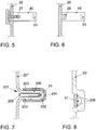
- Fig. 5 It is shown that the component 40 is connected to the lens 20 via a bolt 27 which is cast in the lens 20.
- Fig. 6 again shows an alternative mounting option, in which the component 40 is connected via a latching connection 28 with the lens 20.
- Fig. 7 describes the embodiment of the invention, wherein a lens 20 '', which is provided with a molded-on, lamellar support 200 for a LEDs 51 and a holder 205, prefabricated unit is the carrier 200 and the lens 20 '' are thus integrally connected , The carrier 205 with the LEDs 51 is inserted in a cavity 201 of the carrier 200 and thereby held.
- a cover 202 is applied over the carrier 200, in particular via a latching connection 203 is connected thereto.
- the cover 202 may be opaque, so opaque and provided with a front opening 204, so that the light emitted by the LEDs 51 light penetrates only through the opening 204 to the outside.
- the cover 202 can be configured differently, for example, in terms of the design of translucent or opaque areas.
- a variant of a lens 20 " is shown, wherein the lens 20" is formed such that it can serve for the direct mounting of LEDs 51.
- the lens 20 contact surfaces 206, to which the LEDs 51 and the LEDs 51 associated printed circuit board can be glued, for example.
- Fig. 9 the lighting device 1 according to the invention is shown in isolation and in more detail.
- the trained as a headlight lighting device 1 comprises two identically constructed brackets 30 for lighting, which are each assigned a variety of different, partly divergent light functions (see also Fig. 12,13 . 15 and 19 ).
- the in the Fig. 9 right (outer) holder 30 is slightly smaller than the left (inner) holder 30th
- the holders 30, in particular their base plates 33, are connected to the housing 10 via a receptacle 103 (cf. Fig. 12 ) and arranged in front of reflectors 100, 101 and a surrounding sidewall 102.
- the housing 10 is covered by the lens 20 (see arrow), wherein the lens 20 has a transparent (translucent) wall portion 21 and an underlying opaque (opaque), in particular black wall portion 22.
- the black wall portion 22 is provided with two slot-like through openings 23 and 24, which are arranged one above the other and serve to receive the lamellar members 40 and 41 (see dashed line).
- the components 40 and 41 serve as a carrier for a plurality of LEDs 51 and 52, wherein a direction indicator is realized by the upper part 40 and a daytime running light through the underlying component 41.
- the components 40 and 41 may, for example, from the inside I (see. Figure 3 ) through the through holes 23 and 24 inserted through and with the aid of flanges (indicated by dashed lines in Fig. 17 ) be screwed or glued to the lens 20.
- the lens 20 is shown in isolation. It is in particular from the Fig. 11 it can be seen that the transparent region or the wall section 21 of the light disk 20 and the black region or the wall section 22 are connected to one another by way of a region or wall section 26 which protrudes approximately horizontally or in the light emission direction. Above the transparent wall section 21, a black wall section 220 is present again.
- the brackets 30 are arranged. Furthermore, it can be clearly seen that the wall section 26 is provided with semicircular recesses 25.
- the recesses 25 are translucent and serve to receive the front part of the holder 30 and its base plate 33, which is provided there with the LEDs 50 for the realization of a daytime running light (see also FIGS. 12 and 13 ).
- the holder 30 is arranged in front of the reflectors 100, 101 and the side wall 102.
- the reflectors 100 and 101 are arranged vertically one above the other and separated by means of a receptacle 103, in which the rear part of the base plate 33 is inserted (see dashed line).
- the holder 30 serves to hold various bulbs for generating different light functions, as based on the Fig. 13 and 15 and 19 will be described in more detail.
- the holder 30 serves to hold the light module 34.
- the light module 34 which can also be referred to as a projection module, has a lens (projection lens) 340, a collimator 341 arranged behind it, and a cooling body 342 arranged behind the collimator 341. Furthermore, LEDs for generating light beams for the light module 34 are also accommodated in the light module 34 (not shown).
- the light module 34 is assigned in each case the light function of a dipped beam.
- the reflectors 100 and 101 arranged behind the mount 30 are each assigned the light function of a high beam or a so-called additional high beam (cf. Fig. 15 and 19 ).
- the light module 34 is positioned between two supports 32 carrying a cap-like cover 31, which are connected to the already mentioned base plate 33.
- a light guide 336 is provided, which is arranged in front of the LEDs 50.
- the base plate 33 consists of an upper part 320 and a lower part 330.
- the upper part 320 is formed flat and consists (as well as the lower part 330) of a good heat-conducting material, such as aluminum.
- the upper part 320 can be subdivided into a front part 321 and a rear part 322, wherein the front part 321 is narrower in terms of the surface extension of the base plate 33 relative to the rear part 322 and accounts for only about one third of its width.
- the front part 321 and the rear part 322 integrally merge into one another and are provided with a corrugated surface 323.
- a slot 324 is provided in the area of the front part 321.
- the top 320 of the base 33 is shown from the bottom. It can be seen that it has a support surface 326 in the region of the rear part 322. With the support surface 326, the upper part 320 can be placed on a bearing surface 333 of the lower part 330 of the base plate 33 and secured thereto.
- 320 rectangular recesses 325 can be seen on the underside of the upper part, in each of which an LED chip 60 is adjustably attached.
- One of the LED chips 60 is positioned so that it acts on the reflector 100 with light rays, the other LED chip 60, however, is oriented such that it acts on the reflector 101 with light rays (see also Fig. 15 ).
- the reflectors 100,101 relative to the base plate 33 adjustable / pivotally form (not shown), so that they can be aligned as needed.
- the LED chips 60 may optionally be switched on or off individually or together to produce a desired light distribution of a high beam.
- the lower part 330 is subdivided into a front part 331 and a rear part 332.
- the width extensions of the parts 331 and 332 are adapted to the widthwise extensions of the parts 321 and 322.
- a recess 334 extending from the front is also introduced, which is provided with three holders 335 for LEDs 50.
- the recess 334 is covered with the already mentioned light guide 336.
- a groove 337 is provided in the longitudinal direction of the lower part 330.
- This groove 337 serves for displaceable or adjustable fastening of a carriage 70, which in turn serves for fastening the lens 340 from the light module 34.
- the carriage 70 can protrude through the slot 324 of the upper part 320, wherein the slot 324 enough space for longitudinal displacement of the carriage 70 leaves.
- the guide formed by the slide 70 and the groove 337 may be formed as a so-called dovetail guide.
- the carriage 70 also serves as a holder for an electrical system and as a cable distributor (not shown).
- the LED chips 60 fastened to the base plate 33 cast light beams L1 onto the upper reflector 100 or light beams L2 onto the lower reflector 101.
- the light beams L1 and L2 are reflected by the reflectors 100 and 101 forward in the direction of travel.
- light beams L3 are generated by the light module L3 mounted on the base plate 33 and thus arranged in front of the reflectors 100, 101 and likewise thrown forward in the direction of travel.
- light beams L4 are also thrown forward in the direction of travel by the LEDs 50 fastened in the front region of the base plate 33.
- a desired total light distribution L can be produced flexibly.
- the bulbs 51 and 52 connected to the lens 20 via the components 40 and 41 can be activated (cf. Fig. 9 ).
- Fig. 19 In principle, the arrangement of the reflectors 100 and 101 and the holder 30 together with the light module 34 of the lighting device 1 is again discussed in principle, the two identical units of a lighting device 1 consisting of reflectors 100, 101 and holders 30 being indicated.
- two units consisting of reflectors 100, 101 and holders 30 are arranged next to one another within the lighting device 1.
- two reflectors 100 in a row next to each other and two reflectors 101 are arranged in an underlying row next to each other.
- the overhead reflectors 100 each have a high-beam function LF1 and the underlying reflectors 101 are each assigned an additional high-beam function LF1 '.
- additional high-beam function other light functions that can be assigned to the reflectors 101, such as, for example, fog light, cornering light, city light or the like, are also conceivable.
- the support 30 is provided in each unit in the vertical direction between the reflectors 100 and 101, which in a very compact manner the bulbs for the realization of the high beam function LF1, the additional high beam function LF1 ', a low beam function LF2 and at least part of a daytime running light function LF3.
- the light functions or light beams of different types of optical elements are "networked" with each other.
- the reflection principle is combined or superimposed with the projection principle (projection module or light module 34).
- the light beams L1 and L2 emitted indirectly by the reflectors 100 and 101 can be superimposed by the light beams L3 emitted directly from the projection or light module 34.
- Fig. 15 illustrated reflectors 100,101 a unit can also be arranged offset to one another.
- the reflector 101 associated with the additional high beam LF1 ' can be offset to the front in the direction of the light emission, that is, to the left in the figure.
- a multiplicity of the light-emitting diodes (LEDs) 51 are arranged.
- the component 40 has a cavity 400 which serves to receive a holder 402 for the LEDs 51.
- a cover 403 made of Plexiglas is attached on the holder 402, in turn, a cover 403 made of Plexiglas is attached.
- the cover 403 has a tapered end portion through a slot-like opening 401 introduced into the component 40.
- the LEDs 51 may be formed yellow. However, it is also conceivable to color the cover 403 accordingly.
- the component 40 is replaced by the slot-like passage opening 24 of the lens 20 (see FIG Fig. 9 ) pushed from the back of the lens 20 through and fixed by means of dashed lines indicated flanges 406 at the rear side.
- a component 40 ' is conceivable which, instead of a front slot-like opening, has only a suitably geometrically designed, translucent area 405, which is delimited upwardly and downwardly by opaque (opaque) areas 404.
- a slightly different embodiment 402 'could be provided for a holder of the LEDs 51 (without an additional cover 403), wherein the holder 402' in turn in a recess 400 of the component 40 'can be inserted and held.
Landscapes
- Engineering & Computer Science (AREA)
- General Engineering & Computer Science (AREA)
- Non-Portable Lighting Devices Or Systems Thereof (AREA)
- Lighting Device Outwards From Vehicle And Optical Signal (AREA)
Claims (9)
- Dispositif d'éclairage (1) pour un véhicule automobile (K), comprenant un boîtier (10), au moins un moyen d'éclairage (51) qui au moins contribue à la réalisation d'une fonction lumineuse (LF3) définie, et au moins un disque lumineux (20'''), le disque lumineux (20''') servant au moins également de façon indirecte d'attache pour le moyen d'éclairage (51) au moins au nombre de un, et le moyen d'éclairage (51) au moins au nombre de un étant retenu sur ou dans au moins un composant (200) qui est raccordé au disque lumineux (20'''), le composant (200) dépassant du disque lumineux (20''') vers l'extérieur (A), caractérisé en ce que le composant (200) est constitué en tant que support, du type lamellaire rapporté par moulage avec le disque lumineux (20'''), pour un organe de maintien (205) avec une unité préconfectionnée présentant des moyen d'éclairage (51), l'organe de maintien (205) avec le moyen d'éclairage (51) étant enfiché dans une cavité (201) du support (200) et étant ainsi retenu.
- Dispositif d'éclairage (1) selon la revendication 1, caractérisé en ce que le composant (200) est constitué en forme de lamelles ou d'ailettes.
- Dispositif d'éclairage (1) selon la revendication 1 ou 2, caractérisé en ce qu'un indicateur de changement de direction, un feu de jour, un feu de position, un phare antibrouillard, un feu antibrouillard, un feu de croisement, un feu arrière ou un feu stop est formé par le composant (200) .
- Dispositif d'éclairage (1) selon l'une des revendications précédentes, caractérisé en ce que le disque lumineux (20''') est fabriqué selon le procédé de moulage par injection à plusieurs composants.
- Dispositif d'éclairage (1) selon l'une des revendications précédentes, caractérisé en ce qu'une partie de couverture (202) est mise en place sur le support (200).
- Dispositif d'éclairage (1) selon la revendication 5, caractérisé en ce que la partie de couverture (202) est raccordée au support (200) par le biais d'un raccordement par encliquetage (203).
- Dispositif d'éclairage (1) selon la revendication 5 ou 6, caractérisé en ce que la partie de couverture (202) est constituée de façon opaque et est munie d'un orifice (204) avant.
- Dispositif d'éclairage (1) selon l'une des revendications 5 à 7, caractérisé en ce que la partie de couverture (202) présente des zones transparentes et des zones non transparentes.
- Véhicule automobile (K) avec au moins un dispositif d'éclairage (1) selon au moins l'une des revendications précédentes.
Applications Claiming Priority (2)
| Application Number | Priority Date | Filing Date | Title |
|---|---|---|---|
| DE102011119379A DE102011119379A1 (de) | 2011-11-25 | 2011-11-25 | Beleuchtungsvorrichtung für ein Kraftfahrzeug |
| PCT/EP2012/004656 WO2013075792A2 (fr) | 2011-11-25 | 2012-11-09 | Dispositif d'éclairage pour véhicule à moteur |
Publications (2)
| Publication Number | Publication Date |
|---|---|
| EP2783155A2 EP2783155A2 (fr) | 2014-10-01 |
| EP2783155B1 true EP2783155B1 (fr) | 2019-07-24 |
Family
ID=47754409
Family Applications (1)
| Application Number | Title | Priority Date | Filing Date |
|---|---|---|---|
| EP12826659.0A Active EP2783155B1 (fr) | 2011-11-25 | 2012-11-09 | Dispositif d'éclairage pour véhicule à moteur |
Country Status (5)
| Country | Link |
|---|---|
| EP (1) | EP2783155B1 (fr) |
| KR (1) | KR20140054251A (fr) |
| CN (1) | CN103782086B (fr) |
| DE (1) | DE102011119379A1 (fr) |
| WO (1) | WO2013075792A2 (fr) |
Families Citing this family (11)
| Publication number | Priority date | Publication date | Assignee | Title |
|---|---|---|---|---|
| CN110332498B (zh) * | 2014-03-12 | 2021-10-15 | 大众汽车有限公司 | 汽车和具有附加壳体的汽车照明灯 |
| FR3026821B1 (fr) * | 2014-10-03 | 2019-04-05 | Psa Automobiles Sa. | Feu de signalisation pour vehicule automobile et vehicule comportant un tel feu |
| FR3053763B1 (fr) * | 2016-07-07 | 2020-06-19 | Valeo Iluminacion | Support d’un moyen lumineux pour vehicule automobile |
| SI25296A (sl) * | 2016-10-21 | 2018-04-30 | Hella Saturnus Slovenija d.o.o. | Svetilna naprava na motornem vozilu |
| JP7046640B2 (ja) * | 2018-02-21 | 2022-04-04 | スタンレー電気株式会社 | 車両用灯具 |
| TWI662224B (zh) * | 2018-12-26 | 2019-06-11 | 聯嘉光電股份有限公司 | Led車載線形發光模組 |
| US10578271B1 (en) | 2019-04-17 | 2020-03-03 | Excellence Optoelectronics Inc. | Vehicle LED linear lighting module |
| DE102020114257A1 (de) * | 2020-05-28 | 2021-12-02 | Bayerische Motoren Werke Aktiengesellschaft | Kraftfahrzeug |
| EP3974711B1 (fr) * | 2020-09-24 | 2026-01-07 | ZKW Group GmbH | Phares de véhicule automobile |
| DE102021201145A1 (de) | 2021-02-08 | 2022-08-11 | Volkswagen Aktiengesellschaft | Kraftfahrzeugscheinwerfer und Verfahren zum Betrieb eines Kraftfahrzeugscheinwerfers |
| DE102021117738A1 (de) | 2021-07-09 | 2023-01-12 | Bayerische Motoren Werke Aktiengesellschaft | Scheinwerfervorrichtung für ein Neigefahrzeug sowie Neigefahrzeug mit einer derartigen Scheinwerfervorrichtung |
Citations (2)
| Publication number | Priority date | Publication date | Assignee | Title |
|---|---|---|---|---|
| EP1070633A2 (fr) * | 1999-07-19 | 2001-01-24 | Volkswagen Aktiengesellschaft | Feux avec plusieurs sources de lumière |
| US20090175047A1 (en) * | 2008-01-06 | 2009-07-09 | Keng Lien Industrial Co., Ltd. | Auxiliary luminous trim strip of a car lamp |
Family Cites Families (16)
| Publication number | Priority date | Publication date | Assignee | Title |
|---|---|---|---|---|
| US4680678A (en) * | 1986-07-18 | 1987-07-14 | Stanley Electric Co., Ltd. | Lighting fixture for vehicle |
| JPH0745102A (ja) * | 1993-07-30 | 1995-02-14 | Stanley Electric Co Ltd | 車両用灯具 |
| DE19943255A1 (de) * | 1999-09-10 | 2001-03-15 | Hella Kg Hueck & Co | Leuchteinheit für Fahrzeuge |
| US6533444B2 (en) * | 2000-05-12 | 2003-03-18 | Wen I Auguste Lee | Lighting directional sign for vehicle signal light |
| FR2831647B1 (fr) * | 2001-10-26 | 2004-04-16 | Peugeot Citroen Automobiles Sa | Feu de signalisation de vehicule automobile pour diffusion de faisceaux lumineux indirects |
| DE10336615A1 (de) * | 2002-08-21 | 2005-03-03 | Mayr Tuning Gmbh | Leuchtköper-Einsatz zum nachträglichen Einbau in Standard-Fahrzeugseitenspiegel |
| JP3677271B2 (ja) * | 2002-10-06 | 2005-07-27 | 敏之 仁木 | 自動車用採光発光型コーナーポール |
| DE10311853B4 (de) * | 2003-03-17 | 2005-03-24 | Daimlerchrysler Ag | Scheinwerfer für ein Fahrzeug |
| DE102004039004A1 (de) * | 2004-08-11 | 2006-02-23 | Bayerische Motoren Werke Ag | Kraftfahrzeugleuchte mit einer aus Kunststoff gefertigten Lichtscheibe |
| DE102006014226A1 (de) * | 2006-03-28 | 2007-10-04 | Volkswagen Ag | Beleuchtungseinheit für ein Fahrzeug mit zumindest zwei Lichtquellen |
| DE102006059904B4 (de) * | 2006-12-19 | 2017-02-16 | Hella Kgaa Hueck & Co. | Fahrzeugleuchte |
| DE102007005551A1 (de) * | 2007-01-25 | 2008-07-31 | Schefenacker Vision Systems Germany Gmbh | Leuchte für Fahrzeuge, vorzugsweise für Kraftfahrzeuge |
| DE102007018678A1 (de) | 2007-04-18 | 2008-10-23 | Bayerische Motoren Werke Aktiengesellschaft | Kühlergrill für ein Kraftfahrzeug |
| FR2917348B1 (fr) * | 2007-06-13 | 2010-03-19 | Peugeot Citroen Automobiles Sa | Dispositif d'eclairage et/ou de signalisation pour vehicule automobile, a source de lumiere amovible. |
| DE102008003915A1 (de) * | 2008-01-10 | 2009-07-23 | Heinrich-Beck-Institut Gmbh | LED-Fernscheinwerfer |
| DE202011100750U1 (de) * | 2011-05-16 | 2011-07-04 | Automotive Lighting Reutlingen GmbH, 72762 | Beleuchtungseinrichtung für ein Kraftfahrzeug |
-
2011
- 2011-11-25 DE DE102011119379A patent/DE102011119379A1/de not_active Withdrawn
-
2012
- 2012-11-09 WO PCT/EP2012/004656 patent/WO2013075792A2/fr not_active Ceased
- 2012-11-09 EP EP12826659.0A patent/EP2783155B1/fr active Active
- 2012-11-09 KR KR1020147006832A patent/KR20140054251A/ko not_active Ceased
- 2012-11-09 CN CN201280043852.8A patent/CN103782086B/zh active Active
Patent Citations (2)
| Publication number | Priority date | Publication date | Assignee | Title |
|---|---|---|---|---|
| EP1070633A2 (fr) * | 1999-07-19 | 2001-01-24 | Volkswagen Aktiengesellschaft | Feux avec plusieurs sources de lumière |
| US20090175047A1 (en) * | 2008-01-06 | 2009-07-09 | Keng Lien Industrial Co., Ltd. | Auxiliary luminous trim strip of a car lamp |
Also Published As
| Publication number | Publication date |
|---|---|
| WO2013075792A3 (fr) | 2013-07-18 |
| WO2013075792A2 (fr) | 2013-05-30 |
| CN103782086B (zh) | 2017-04-12 |
| CN103782086A (zh) | 2014-05-07 |
| EP2783155A2 (fr) | 2014-10-01 |
| DE102011119379A1 (de) | 2013-05-29 |
| KR20140054251A (ko) | 2014-05-08 |
Similar Documents
| Publication | Publication Date | Title |
|---|---|---|
| WO2013075792A2 (fr) | Dispositif d'éclairage pour véhicule à moteur | |
| DE102010007172B4 (de) | Lichtleiter für eine Fahrzeugleuchtenanordnung | |
| EP2339228B1 (fr) | Module d'éclairage pour un dispositif d'éclairage et dispositif d'éclairage d'un véhicule automobile doté d'un tel module d'éclairage | |
| DE102006034353B4 (de) | Fahrzeugleuchte | |
| DE102014205996A1 (de) | Fahrzeug-Richtungsanzeiger-Leuchte | |
| EP3404314B1 (fr) | Module d'éclairage d'un phare de véhicule automobile et phare de véhicule automobile doté d'un tel module d'éclairage | |
| DE102010045435A1 (de) | Projektionsscheinwerfer für Fahrzeuge | |
| DE102007018985A1 (de) | Beleuchtungsvorrichtung für Fahrzeuge | |
| DE19646042B4 (de) | Fahrzeug-Beleuchtungseinrichtung | |
| DE20211305U1 (de) | Beleuchtungseinrichtung für ein Kraftfahrzeug mit mehreren Leuchteinheiten | |
| EP1852306A1 (fr) | Eclairage doté d'au moins une unité d'élément lumineux pour véhicules, de préférence pour véhicules automobiles | |
| DE10337615B3 (de) | Leuchtvorrichtung für Fahrzeuge | |
| DE102011119372B4 (de) | Beleuchtungsvorrichtung für ein Kraftfahrzeug mit einem verschiebbaren Schlitten, der teils durch einen Kühlkörper der Beleuchtungsvorrichtung ragt und zur verschiebbaren Befestigung einer Linse eines Lichtmoduls dient, und Kraftfahrzeug mit dieser Beleuchtungsvorrichtung | |
| EP3792111B1 (fr) | Luminaire | |
| DE102020003849A1 (de) | Motorradleuchte zur Realisierung mindestens einer Leuchtenfunktion | |
| EP3625500B1 (fr) | Module lumineux d'un projecteur de véhicule à moteur et projecteur de véhicule à moteur comprenant ledit module lumineux | |
| DE19838224C2 (de) | Frontleuchtenanordnung für Kraftfahrzeuge | |
| DE102007042624A1 (de) | Leuchtenanordnung | |
| DE102011084890A1 (de) | Lichtmodul einer Beleuchtungseinrichtung eines Kraftfahrzeugs | |
| DE202004001720U1 (de) | Autoleuchte | |
| EP1536979B1 (fr) | Rétroviseur extérieur pour vehicules , muni d'un témoin lumineux | |
| DE102007042625A1 (de) | Leuchtenanordnung | |
| DE102011119382B4 (de) | Beleuchtungsvorrichtung für ein Kraftfahrzeug mit einer Lichtscheibe, an der mindestens ein Träger für LEDs in Fortsetzung von Kühlergrill-Lamellen nach außen absteht | |
| DE10207431B4 (de) | Mehrfunktions-Signalleuchte eines Kraftfahrzeugs | |
| DE19838911B4 (de) | Beleuchtungseinrichtung eines Fahrzeugs |
Legal Events
| Date | Code | Title | Description |
|---|---|---|---|
| PUAI | Public reference made under article 153(3) epc to a published international application that has entered the european phase |
Free format text: ORIGINAL CODE: 0009012 |
|
| 17P | Request for examination filed |
Effective date: 20140625 |
|
| AK | Designated contracting states |
Kind code of ref document: A2 Designated state(s): AL AT BE BG CH CY CZ DE DK EE ES FI FR GB GR HR HU IE IS IT LI LT LU LV MC MK MT NL NO PL PT RO RS SE SI SK SM TR |
|
| DAX | Request for extension of the european patent (deleted) | ||
| STAA | Information on the status of an ep patent application or granted ep patent |
Free format text: STATUS: EXAMINATION IS IN PROGRESS |
|
| 17Q | First examination report despatched |
Effective date: 20181105 |
|
| REG | Reference to a national code |
Ref country code: DE Ref legal event code: R079 Ref document number: 502012015067 Country of ref document: DE Free format text: PREVIOUS MAIN CLASS: F21S0008100000 Ipc: F21S0041190000 |
|
| RIC1 | Information provided on ipc code assigned before grant |
Ipc: F21S 41/19 20180101AFI20190305BHEP Ipc: F21S 41/20 20180101ALI20190305BHEP Ipc: F21S 43/19 20180101ALI20190305BHEP Ipc: F21S 43/20 20180101ALI20190305BHEP |
|
| GRAP | Despatch of communication of intention to grant a patent |
Free format text: ORIGINAL CODE: EPIDOSNIGR1 |
|
| STAA | Information on the status of an ep patent application or granted ep patent |
Free format text: STATUS: GRANT OF PATENT IS INTENDED |
|
| INTG | Intention to grant announced |
Effective date: 20190426 |
|
| GRAS | Grant fee paid |
Free format text: ORIGINAL CODE: EPIDOSNIGR3 |
|
| GRAA | (expected) grant |
Free format text: ORIGINAL CODE: 0009210 |
|
| STAA | Information on the status of an ep patent application or granted ep patent |
Free format text: STATUS: THE PATENT HAS BEEN GRANTED |
|
| AK | Designated contracting states |
Kind code of ref document: B1 Designated state(s): AL AT BE BG CH CY CZ DE DK EE ES FI FR GB GR HR HU IE IS IT LI LT LU LV MC MK MT NL NO PL PT RO RS SE SI SK SM TR |
|
| REG | Reference to a national code |
Ref country code: GB Ref legal event code: FG4D Free format text: NOT ENGLISH |
|
| REG | Reference to a national code |
Ref country code: CH Ref legal event code: EP |
|
| REG | Reference to a national code |
Ref country code: DE Ref legal event code: R096 Ref document number: 502012015067 Country of ref document: DE |
|
| REG | Reference to a national code |
Ref country code: AT Ref legal event code: REF Ref document number: 1158628 Country of ref document: AT Kind code of ref document: T Effective date: 20190815 |
|
| REG | Reference to a national code |
Ref country code: IE Ref legal event code: FG4D Free format text: LANGUAGE OF EP DOCUMENT: GERMAN |
|
| REG | Reference to a national code |
Ref country code: NL Ref legal event code: MP Effective date: 20190724 |
|
| REG | Reference to a national code |
Ref country code: LT Ref legal event code: MG4D |
|
| PG25 | Lapsed in a contracting state [announced via postgrant information from national office to epo] |
Ref country code: SE Free format text: LAPSE BECAUSE OF FAILURE TO SUBMIT A TRANSLATION OF THE DESCRIPTION OR TO PAY THE FEE WITHIN THE PRESCRIBED TIME-LIMIT Effective date: 20190724 Ref country code: HR Free format text: LAPSE BECAUSE OF FAILURE TO SUBMIT A TRANSLATION OF THE DESCRIPTION OR TO PAY THE FEE WITHIN THE PRESCRIBED TIME-LIMIT Effective date: 20190724 Ref country code: LT Free format text: LAPSE BECAUSE OF FAILURE TO SUBMIT A TRANSLATION OF THE DESCRIPTION OR TO PAY THE FEE WITHIN THE PRESCRIBED TIME-LIMIT Effective date: 20190724 Ref country code: NL Free format text: LAPSE BECAUSE OF FAILURE TO SUBMIT A TRANSLATION OF THE DESCRIPTION OR TO PAY THE FEE WITHIN THE PRESCRIBED TIME-LIMIT Effective date: 20190724 Ref country code: FI Free format text: LAPSE BECAUSE OF FAILURE TO SUBMIT A TRANSLATION OF THE DESCRIPTION OR TO PAY THE FEE WITHIN THE PRESCRIBED TIME-LIMIT Effective date: 20190724 Ref country code: PT Free format text: LAPSE BECAUSE OF FAILURE TO SUBMIT A TRANSLATION OF THE DESCRIPTION OR TO PAY THE FEE WITHIN THE PRESCRIBED TIME-LIMIT Effective date: 20191125 Ref country code: NO Free format text: LAPSE BECAUSE OF FAILURE TO SUBMIT A TRANSLATION OF THE DESCRIPTION OR TO PAY THE FEE WITHIN THE PRESCRIBED TIME-LIMIT Effective date: 20191024 Ref country code: BG Free format text: LAPSE BECAUSE OF FAILURE TO SUBMIT A TRANSLATION OF THE DESCRIPTION OR TO PAY THE FEE WITHIN THE PRESCRIBED TIME-LIMIT Effective date: 20191024 |
|
| PG25 | Lapsed in a contracting state [announced via postgrant information from national office to epo] |
Ref country code: AL Free format text: LAPSE BECAUSE OF FAILURE TO SUBMIT A TRANSLATION OF THE DESCRIPTION OR TO PAY THE FEE WITHIN THE PRESCRIBED TIME-LIMIT Effective date: 20190724 Ref country code: ES Free format text: LAPSE BECAUSE OF FAILURE TO SUBMIT A TRANSLATION OF THE DESCRIPTION OR TO PAY THE FEE WITHIN THE PRESCRIBED TIME-LIMIT Effective date: 20190724 Ref country code: IS Free format text: LAPSE BECAUSE OF FAILURE TO SUBMIT A TRANSLATION OF THE DESCRIPTION OR TO PAY THE FEE WITHIN THE PRESCRIBED TIME-LIMIT Effective date: 20191124 Ref country code: LV Free format text: LAPSE BECAUSE OF FAILURE TO SUBMIT A TRANSLATION OF THE DESCRIPTION OR TO PAY THE FEE WITHIN THE PRESCRIBED TIME-LIMIT Effective date: 20190724 Ref country code: GR Free format text: LAPSE BECAUSE OF FAILURE TO SUBMIT A TRANSLATION OF THE DESCRIPTION OR TO PAY THE FEE WITHIN THE PRESCRIBED TIME-LIMIT Effective date: 20191025 Ref country code: RS Free format text: LAPSE BECAUSE OF FAILURE TO SUBMIT A TRANSLATION OF THE DESCRIPTION OR TO PAY THE FEE WITHIN THE PRESCRIBED TIME-LIMIT Effective date: 20190724 |
|
| PG25 | Lapsed in a contracting state [announced via postgrant information from national office to epo] |
Ref country code: TR Free format text: LAPSE BECAUSE OF FAILURE TO SUBMIT A TRANSLATION OF THE DESCRIPTION OR TO PAY THE FEE WITHIN THE PRESCRIBED TIME-LIMIT Effective date: 20190724 |
|
| PG25 | Lapsed in a contracting state [announced via postgrant information from national office to epo] |
Ref country code: IT Free format text: LAPSE BECAUSE OF FAILURE TO SUBMIT A TRANSLATION OF THE DESCRIPTION OR TO PAY THE FEE WITHIN THE PRESCRIBED TIME-LIMIT Effective date: 20190724 Ref country code: RO Free format text: LAPSE BECAUSE OF FAILURE TO SUBMIT A TRANSLATION OF THE DESCRIPTION OR TO PAY THE FEE WITHIN THE PRESCRIBED TIME-LIMIT Effective date: 20190724 Ref country code: DK Free format text: LAPSE BECAUSE OF FAILURE TO SUBMIT A TRANSLATION OF THE DESCRIPTION OR TO PAY THE FEE WITHIN THE PRESCRIBED TIME-LIMIT Effective date: 20190724 Ref country code: PL Free format text: LAPSE BECAUSE OF FAILURE TO SUBMIT A TRANSLATION OF THE DESCRIPTION OR TO PAY THE FEE WITHIN THE PRESCRIBED TIME-LIMIT Effective date: 20190724 Ref country code: EE Free format text: LAPSE BECAUSE OF FAILURE TO SUBMIT A TRANSLATION OF THE DESCRIPTION OR TO PAY THE FEE WITHIN THE PRESCRIBED TIME-LIMIT Effective date: 20190724 |
|
| PG25 | Lapsed in a contracting state [announced via postgrant information from national office to epo] |
Ref country code: SK Free format text: LAPSE BECAUSE OF FAILURE TO SUBMIT A TRANSLATION OF THE DESCRIPTION OR TO PAY THE FEE WITHIN THE PRESCRIBED TIME-LIMIT Effective date: 20190724 Ref country code: IS Free format text: LAPSE BECAUSE OF FAILURE TO SUBMIT A TRANSLATION OF THE DESCRIPTION OR TO PAY THE FEE WITHIN THE PRESCRIBED TIME-LIMIT Effective date: 20200224 Ref country code: SM Free format text: LAPSE BECAUSE OF FAILURE TO SUBMIT A TRANSLATION OF THE DESCRIPTION OR TO PAY THE FEE WITHIN THE PRESCRIBED TIME-LIMIT Effective date: 20190724 Ref country code: CZ Free format text: LAPSE BECAUSE OF FAILURE TO SUBMIT A TRANSLATION OF THE DESCRIPTION OR TO PAY THE FEE WITHIN THE PRESCRIBED TIME-LIMIT Effective date: 20190724 |
|
| REG | Reference to a national code |
Ref country code: DE Ref legal event code: R097 Ref document number: 502012015067 Country of ref document: DE |
|
| REG | Reference to a national code |
Ref country code: CH Ref legal event code: PL |
|
| PLBE | No opposition filed within time limit |
Free format text: ORIGINAL CODE: 0009261 |
|
| STAA | Information on the status of an ep patent application or granted ep patent |
Free format text: STATUS: NO OPPOSITION FILED WITHIN TIME LIMIT |
|
| PG2D | Information on lapse in contracting state deleted |
Ref country code: IS |
|
| PG25 | Lapsed in a contracting state [announced via postgrant information from national office to epo] |
Ref country code: MC Free format text: LAPSE BECAUSE OF FAILURE TO SUBMIT A TRANSLATION OF THE DESCRIPTION OR TO PAY THE FEE WITHIN THE PRESCRIBED TIME-LIMIT Effective date: 20190724 Ref country code: LI Free format text: LAPSE BECAUSE OF NON-PAYMENT OF DUE FEES Effective date: 20191130 Ref country code: CH Free format text: LAPSE BECAUSE OF NON-PAYMENT OF DUE FEES Effective date: 20191130 Ref country code: LU Free format text: LAPSE BECAUSE OF NON-PAYMENT OF DUE FEES Effective date: 20191109 |
|
| 26N | No opposition filed |
Effective date: 20200603 |
|
| REG | Reference to a national code |
Ref country code: BE Ref legal event code: MM Effective date: 20191130 |
|
| PG25 | Lapsed in a contracting state [announced via postgrant information from national office to epo] |
Ref country code: SI Free format text: LAPSE BECAUSE OF FAILURE TO SUBMIT A TRANSLATION OF THE DESCRIPTION OR TO PAY THE FEE WITHIN THE PRESCRIBED TIME-LIMIT Effective date: 20190724 |
|
| PG25 | Lapsed in a contracting state [announced via postgrant information from national office to epo] |
Ref country code: IE Free format text: LAPSE BECAUSE OF NON-PAYMENT OF DUE FEES Effective date: 20191109 |
|
| PG25 | Lapsed in a contracting state [announced via postgrant information from national office to epo] |
Ref country code: BE Free format text: LAPSE BECAUSE OF NON-PAYMENT OF DUE FEES Effective date: 20191130 |
|
| REG | Reference to a national code |
Ref country code: AT Ref legal event code: MM01 Ref document number: 1158628 Country of ref document: AT Kind code of ref document: T Effective date: 20191109 |
|
| PG25 | Lapsed in a contracting state [announced via postgrant information from national office to epo] |
Ref country code: AT Free format text: LAPSE BECAUSE OF NON-PAYMENT OF DUE FEES Effective date: 20191109 |
|
| PG25 | Lapsed in a contracting state [announced via postgrant information from national office to epo] |
Ref country code: CY Free format text: LAPSE BECAUSE OF FAILURE TO SUBMIT A TRANSLATION OF THE DESCRIPTION OR TO PAY THE FEE WITHIN THE PRESCRIBED TIME-LIMIT Effective date: 20190724 |
|
| PG25 | Lapsed in a contracting state [announced via postgrant information from national office to epo] |
Ref country code: HU Free format text: LAPSE BECAUSE OF FAILURE TO SUBMIT A TRANSLATION OF THE DESCRIPTION OR TO PAY THE FEE WITHIN THE PRESCRIBED TIME-LIMIT; INVALID AB INITIO Effective date: 20121109 Ref country code: MT Free format text: LAPSE BECAUSE OF FAILURE TO SUBMIT A TRANSLATION OF THE DESCRIPTION OR TO PAY THE FEE WITHIN THE PRESCRIBED TIME-LIMIT Effective date: 20190724 |
|
| PG25 | Lapsed in a contracting state [announced via postgrant information from national office to epo] |
Ref country code: MK Free format text: LAPSE BECAUSE OF FAILURE TO SUBMIT A TRANSLATION OF THE DESCRIPTION OR TO PAY THE FEE WITHIN THE PRESCRIBED TIME-LIMIT Effective date: 20190724 |
|
| P01 | Opt-out of the competence of the unified patent court (upc) registered |
Effective date: 20230523 |
|
| PGFP | Annual fee paid to national office [announced via postgrant information from national office to epo] |
Ref country code: DE Payment date: 20251130 Year of fee payment: 14 |
|
| PGFP | Annual fee paid to national office [announced via postgrant information from national office to epo] |
Ref country code: GB Payment date: 20251125 Year of fee payment: 14 |
|
| PGFP | Annual fee paid to national office [announced via postgrant information from national office to epo] |
Ref country code: FR Payment date: 20251124 Year of fee payment: 14 |