EP2783602A1 - Matelas, procédé d'étalonnage de capteur de pression et dispositif de lit - Google Patents
Matelas, procédé d'étalonnage de capteur de pression et dispositif de lit Download PDFInfo
- Publication number
- EP2783602A1 EP2783602A1 EP20120850777 EP12850777A EP2783602A1 EP 2783602 A1 EP2783602 A1 EP 2783602A1 EP 20120850777 EP20120850777 EP 20120850777 EP 12850777 A EP12850777 A EP 12850777A EP 2783602 A1 EP2783602 A1 EP 2783602A1
- Authority
- EP
- European Patent Office
- Prior art keywords
- pressure
- calibration
- cells
- cell
- pressure sensor
- Prior art date
- Legal status (The legal status is an assumption and is not a legal conclusion. Google has not performed a legal analysis and makes no representation as to the accuracy of the status listed.)
- Granted
Links
Images




Classifications
-
- A—HUMAN NECESSITIES
- A61—MEDICAL OR VETERINARY SCIENCE; HYGIENE
- A61G—TRANSPORT, PERSONAL CONVEYANCES, OR ACCOMMODATION SPECIALLY ADAPTED FOR PATIENTS OR DISABLED PERSONS; OPERATING TABLES OR CHAIRS; CHAIRS FOR DENTISTRY; FUNERAL DEVICES
- A61G7/00—Beds specially adapted for nursing; Devices for lifting patients or disabled persons
- A61G7/05—Parts, details or accessories of beds
- A61G7/057—Arrangements for preventing bed-sores or for supporting patients with burns, e.g. mattresses specially adapted therefor
- A61G7/05769—Arrangements for preventing bed-sores or for supporting patients with burns, e.g. mattresses specially adapted therefor with inflatable chambers
-
- A—HUMAN NECESSITIES
- A47—FURNITURE; DOMESTIC ARTICLES OR APPLIANCES; COFFEE MILLS; SPICE MILLS; SUCTION CLEANERS IN GENERAL
- A47C—CHAIRS; SOFAS; BEDS
- A47C27/00—Spring, stuffed or fluid mattresses or cushions specially adapted for chairs, beds or sofas
- A47C27/08—Fluid mattresses
- A47C27/081—Fluid mattresses of pneumatic type
- A47C27/083—Fluid mattresses of pneumatic type with pressure control, e.g. with pressure sensors
-
- A—HUMAN NECESSITIES
- A47—FURNITURE; DOMESTIC ARTICLES OR APPLIANCES; COFFEE MILLS; SPICE MILLS; SUCTION CLEANERS IN GENERAL
- A47C—CHAIRS; SOFAS; BEDS
- A47C27/00—Spring, stuffed or fluid mattresses or cushions specially adapted for chairs, beds or sofas
- A47C27/08—Fluid mattresses
- A47C27/081—Fluid mattresses of pneumatic type
- A47C27/084—Fluid mattresses of pneumatic type self inflating
-
- A—HUMAN NECESSITIES
- A61—MEDICAL OR VETERINARY SCIENCE; HYGIENE
- A61B—DIAGNOSIS; SURGERY; IDENTIFICATION
- A61B5/00—Measuring for diagnostic purposes; Identification of persons
- A61B5/44—Detecting, measuring or recording for evaluating the integumentary system, e.g. skin, hair or nails
- A61B5/441—Skin evaluation, e.g. for skin disorder diagnosis
- A61B5/447—Skin evaluation, e.g. for skin disorder diagnosis specially adapted for aiding the prevention of ulcer or pressure sore development, i.e. before the ulcer or sore has developed
-
- A—HUMAN NECESSITIES
- A61—MEDICAL OR VETERINARY SCIENCE; HYGIENE
- A61B—DIAGNOSIS; SURGERY; IDENTIFICATION
- A61B5/00—Measuring for diagnostic purposes; Identification of persons
- A61B5/68—Arrangements of detecting, measuring or recording means, e.g. sensors, in relation to patient
- A61B5/6887—Arrangements of detecting, measuring or recording means, e.g. sensors, in relation to patient mounted on external non-worn devices, e.g. non-medical devices
- A61B5/6892—Mats
-
- A—HUMAN NECESSITIES
- A61—MEDICAL OR VETERINARY SCIENCE; HYGIENE
- A61G—TRANSPORT, PERSONAL CONVEYANCES, OR ACCOMMODATION SPECIALLY ADAPTED FOR PATIENTS OR DISABLED PERSONS; OPERATING TABLES OR CHAIRS; CHAIRS FOR DENTISTRY; FUNERAL DEVICES
- A61G7/00—Beds specially adapted for nursing; Devices for lifting patients or disabled persons
- A61G7/05—Parts, details or accessories of beds
- A61G7/057—Arrangements for preventing bed-sores or for supporting patients with burns, e.g. mattresses specially adapted therefor
- A61G7/05769—Arrangements for preventing bed-sores or for supporting patients with burns, e.g. mattresses specially adapted therefor with inflatable chambers
- A61G7/05776—Arrangements for preventing bed-sores or for supporting patients with burns, e.g. mattresses specially adapted therefor with inflatable chambers with at least two groups of alternately inflated chambers
-
- G—PHYSICS
- G01—MEASURING; TESTING
- G01L—MEASURING FORCE, STRESS, TORQUE, WORK, MECHANICAL POWER, MECHANICAL EFFICIENCY, OR FLUID PRESSURE
- G01L27/00—Testing or calibrating of apparatus for measuring fluid pressure
- G01L27/002—Calibrating, i.e. establishing true relation between transducer output value and value to be measured, zeroing, linearising or span error determination
-
- G—PHYSICS
- G01—MEASURING; TESTING
- G01L—MEASURING FORCE, STRESS, TORQUE, WORK, MECHANICAL POWER, MECHANICAL EFFICIENCY, OR FLUID PRESSURE
- G01L27/00—Testing or calibrating of apparatus for measuring fluid pressure
- G01L27/002—Calibrating, i.e. establishing true relation between transducer output value and value to be measured, zeroing, linearising or span error determination
- G01L27/005—Apparatus for calibrating pressure sensors
-
- A—HUMAN NECESSITIES
- A61—MEDICAL OR VETERINARY SCIENCE; HYGIENE
- A61B—DIAGNOSIS; SURGERY; IDENTIFICATION
- A61B2560/00—Constructional details of operational features of apparatus; Accessories for medical measuring apparatus
- A61B2560/02—Operational features
- A61B2560/0223—Operational features of calibration, e.g. protocols for calibrating sensors
-
- A—HUMAN NECESSITIES
- A61—MEDICAL OR VETERINARY SCIENCE; HYGIENE
- A61B—DIAGNOSIS; SURGERY; IDENTIFICATION
- A61B2560/00—Constructional details of operational features of apparatus; Accessories for medical measuring apparatus
- A61B2560/02—Operational features
- A61B2560/0242—Operational features adapted to measure environmental factors, e.g. temperature, pollution
- A61B2560/0247—Operational features adapted to measure environmental factors, e.g. temperature, pollution for compensation or correction of the measured physiological value
-
- A—HUMAN NECESSITIES
- A61—MEDICAL OR VETERINARY SCIENCE; HYGIENE
- A61B—DIAGNOSIS; SURGERY; IDENTIFICATION
- A61B2562/00—Details of sensors; Constructional details of sensor housings or probes; Accessories for sensors
- A61B2562/04—Arrangements of multiple sensors of the same type
- A61B2562/046—Arrangements of multiple sensors of the same type in a matrix array
-
- A—HUMAN NECESSITIES
- A61—MEDICAL OR VETERINARY SCIENCE; HYGIENE
- A61B—DIAGNOSIS; SURGERY; IDENTIFICATION
- A61B2562/00—Details of sensors; Constructional details of sensor housings or probes; Accessories for sensors
- A61B2562/16—Details of sensor housings or probes; Details of structural supports for sensors
- A61B2562/168—Fluid filled sensor housings
-
- A—HUMAN NECESSITIES
- A61—MEDICAL OR VETERINARY SCIENCE; HYGIENE
- A61G—TRANSPORT, PERSONAL CONVEYANCES, OR ACCOMMODATION SPECIALLY ADAPTED FOR PATIENTS OR DISABLED PERSONS; OPERATING TABLES OR CHAIRS; CHAIRS FOR DENTISTRY; FUNERAL DEVICES
- A61G2203/00—General characteristics of devices
- A61G2203/30—General characteristics of devices characterised by sensor means
- A61G2203/34—General characteristics of devices characterised by sensor means for pressure
-
- A—HUMAN NECESSITIES
- A61—MEDICAL OR VETERINARY SCIENCE; HYGIENE
- A61G—TRANSPORT, PERSONAL CONVEYANCES, OR ACCOMMODATION SPECIALLY ADAPTED FOR PATIENTS OR DISABLED PERSONS; OPERATING TABLES OR CHAIRS; CHAIRS FOR DENTISTRY; FUNERAL DEVICES
- A61G2203/00—General characteristics of devices
- A61G2203/30—General characteristics of devices characterised by sensor means
- A61G2203/42—General characteristics of devices characterised by sensor means for inclination
-
- A—HUMAN NECESSITIES
- A61—MEDICAL OR VETERINARY SCIENCE; HYGIENE
- A61G—TRANSPORT, PERSONAL CONVEYANCES, OR ACCOMMODATION SPECIALLY ADAPTED FOR PATIENTS OR DISABLED PERSONS; OPERATING TABLES OR CHAIRS; CHAIRS FOR DENTISTRY; FUNERAL DEVICES
- A61G2203/00—General characteristics of devices
- A61G2203/30—General characteristics of devices characterised by sensor means
- A61G2203/44—General characteristics of devices characterised by sensor means for weight
-
- A—HUMAN NECESSITIES
- A61—MEDICAL OR VETERINARY SCIENCE; HYGIENE
- A61G—TRANSPORT, PERSONAL CONVEYANCES, OR ACCOMMODATION SPECIALLY ADAPTED FOR PATIENTS OR DISABLED PERSONS; OPERATING TABLES OR CHAIRS; CHAIRS FOR DENTISTRY; FUNERAL DEVICES
- A61G7/00—Beds specially adapted for nursing; Devices for lifting patients or disabled persons
- A61G7/002—Beds specially adapted for nursing; Devices for lifting patients or disabled persons having adjustable mattress frame
- A61G7/015—Beds specially adapted for nursing; Devices for lifting patients or disabled persons having adjustable mattress frame divided into different adjustable sections, e.g. for Gatch position
Definitions
- the present invention relates to a mattress and the like including a plurality of cells, pressure sensors for detecting the internal pressure of cells, a pump connected to regulate the air quantities in individual cells, and communication paths connected from the pump to the plurality of cells.
- the air mattress formed of cells inflated by air pressure has been conventionally known.
- the air mattress is used as a body pressure dispersion mattress and the like, and this mattress is useful for preventing bedsores from occurring over the body of a patient by dispersing the load of the body of the patient lying over the mattress to reduce the pressure acting on the body.
- internal pressure control For individual cells of the air mattress, it is necessary to regulate the pressure inside each cell within a prescribed range (which will be referred to hereinbelow as “internal pressure control").
- internal pressure control the pressure is measured first using a pressure sensor, then based on themeasuredpressure, each cell is inflated or deflated to regulate the pressure.
- Patent Document 1
- the air mattress is formed of a plurality of branches of cells, each branch being provided with a pressure sensor. For these cells, when zero-point adjustment is performed for each branch it is necessary to perform adjustment by switching the branches one to another as in the apparatus described in the aforementioned Patent Document 1, which has been quite inconvenient.
- a mattress of the present invention is one including a plurality of cells; pressure sensors for detecting the internal pressure of the cells; a pump connected to adjust the amount of air in each cell; communication paths from the pump to the plurality of cells; selector valves, arranged on the communication paths between each of the cells and the pump, and capable of switching between, at least, a state for creating communication between the cell and the pump and a state for opening the cell to atmospheric pressure; and a calibration means for calibrating the pressure sensors, and is characterized in that the calibration means includes:
- the mattress of the present invention is characterized in that the selector valves installed for the plurality of cells are changed over to communicate with the pump so as to make the plurality of cells have the same pressure.
- the mattress of the present invention further comprises an inter-cell selector valve for creating communication between the plurality of cells, and is characterized in that the internal pressure adjustment means opens the inter-cell selector valve to thereby make the plurality of cells have the DOU pressure.
- the mattress of the present invention further comprises a mattress status detectingmeans for detecting a state of themattress, and is characterized in that the calibration means performs calibration of the pressure sensors when the mattress is in a state in which calibration of the pressure sensor is calibratable.
- a pressure sensor calibration method of the present invention is one that is used for a mattress including a plurality of cells; pressure sensors for detecting internal pressure of the cells; a pump connected to adjust the amount of air in each cell; communication paths from the pump to the plurality of cells; and a selector valve, arranged on the communication paths between each of the cells and the pump, and capable of switching between, at least, a state for creating communication between the cell and the pump and a state for opening the cell to atmospheric pressure, and a calibration step for calibrating the pressure sensors, comprising the steps of:
- a bed device of the present invention is one including: a mattress including a plurality of cells; pressure sensors for detecting internal pressure of the cells; a pump connected to adjust the amount of air in each cell; and communication paths from the pump to plurality of cells, a bed body; selector valves, arranged on the communication paths between each of the cells and the pump, and capable of switching between, at least, a state for creating communication between the cell and the pump and a state for opening the cell to atmospheric pressure; and, a calibration means for calibrating the pressure sensor, and is characterized in that the calibration means includes:
- the bed device of the present invention further comprises a bed status detecting means for detecting a state of the bed body, and is characterized in that the calibration means performs calibration of the pressure sensors when the bed body is in a state in which calibration of the pressure sensor is calibratable.
- the process of the present invention determines whether the pressure detected by the pressure sensor connected to the calibration standard cell has continuously fallen within a regulated pressure range at calibration for a regulated duration at calibration when the selector valve connected to the calibration standard cell is opened to atmospheric pressure, performs zero-point adjustment of the pressure sensor connected to the calibration standard cell, based on the pressure value detected by the pressure sensor when the pressure detected by the pressure sensor connected to the calibration standard cell has continuously fallen within the regulated pressure range at calibration for the regulated duration at calibration, then creates communication of the selector valves for the plurality of cells to perform internal pressure adjustment of the plurality of cells to a predetermined internal pressure value, based on the pressure value detected by the pressure sensor connected to the calibration standard cell.
- FIG. 1 is a diagram for illustrating the overview of a bed device 1 in the present embodiment.
- FIG. 2 is a front view showing bed device 1, viewed from the foot side (the controller 40 side in FIG. 1 ).
- Bed device 1 includes a mattress body 10 mounted on a base 30.
- mattress body 10 is formed of a plurality of cells 14 arranged contiguously in the longitudinal direction. These cells are enfolded by a cover 12 of a top cover and a bottom cover, to form mattress body 10.
- Air blow tubes 42 Connected to individual cells (cells 14) are air blow tubes 42 from a controller 40.
- An air blow tube 44 from a pump unit 50 is connected to controller 40.
- controller 40 and pump unit 50 are connected to each other by a control cable 52 so that various control signals are exchanged therebetween.
- Connected to pump unit 50 is a control cable 54 from without as well as a power cable 56 for driving the pump.
- Air blow tube 42 is connected to a selector valve by way of an air blow tube connector.
- the selector valve is connected to pump unit 50 by way of the air blow tube.
- air blow tubes 42 as the communication paths may be constructed so that a single tube output from pump unit 50 is branched into a plurality of tubes each of which is input to individual branch, or so that a plurality of tubes are output from pump unit 50.
- any configuration may be accepted as long as each cell can be made to take the same pressure value with others when an operation for making each cell communicate with others.
- each cell (cell 14) will be described with reference to FIG. 2 .
- the cells are separated into branches A to G, each connected to pump unit 50.
- cells 14A are connected to air blow tube 42A as branch A. All cells 14A belonging to branch A are equally inflated or deflated by air blow tube 42A.
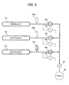
- selector valves will be described with reference to FIGS. 3 to 7 .
- the operation of the selector valves will be described by giving an example where three cell branches are connected.
- cell branch 1 14a
- cell branch 2 14b
- cell branch 3 14c
- an air blow tube as a communication path is connected so as to be able to supply air into or suction air from, the cells.
- each cell branch includes selector valves connected thereto.
- the selector valve is formed of a valve element of, for example, a plunger.
- Each cell branch includes a selector valve (valve element) connected to the pump side and a selector valve (valve element) for releasing the air from the cell branch to the atmosphere.
- cell branch 1 (14a) has a selector valve 60a connected to the pump and a selector valve 62a for releasing itself to atmospheric pressure.
- Cell branch 2 (14b) has a selector valve 60b connected to the pump and a selector valve 62b for releasing itself to atmospheric pressure.
- Cell branch 3 (14c) has a selector valve 60c connected to the pump and a selector valve 62c for releasing itself to atmospheric pressure.
- the selector valve connected to each cell branch may be formed of either, separate selector valves, or a single selector valve. That is, it is possible to provide a single selector valve that can operate to select a state in which the branch is connected to the pump side to be able to inflate and deflate, a state capable of releasing the air to atmospheric pressure, or a state of sealing the cells, in accordance with an opening and closing state of the valve element.
- a pressure sensor is connected between the selector valve and the cell branch.
- a pressure sensor 150a is connected to cell branch 1 (14a), a pressure senor 150b to cell branch 2 (14b), and a pressure sensor 150c to cell branch 3 (14c). The pressure sensor is able to detect the internal pressure of the cells (branch) connected thereto.
- a selector valve 64 is connected to pump unit 50. Therefore, when selector valve 64 is closed and selector valves 60a to 60c are opened, for instance, the same air pressure acts on cell branches 1 to 3.
- FIG. 3 shows a state in which all the selector valves are closed. In this state, each of the cell branches has a different pressure from the others.
- FIG. 4 shows a state in which selector valve 62c of cell branch 3 (14c) is opened. In this state, cell branch 14c is released to atmospheric pressure, so that pressure sensor 150c detects the pressure value of atmospheric pressure.
- FIG. 5 shows a state in which selector valves 60a to 60c are opened after selector valve 62c has been closed. Since selector valve 64 is also closed, cell branches 1 (14a) to 3 (14c) are communicated so that the same pressure value (internal pressure) is detected.
- FIG. 6 shows a state in which selector valve 64 is also opened.
- air is supplied to or drawn from the cell branches by the operation of pump unit 50 to thereby adjust the pressure to an appropriate value.
- the sensor that detects the pressure value (internal pressure) of the cell branches is pressure sensor 150c that is connected to cell branch 3 (14c).
- FIG. 7 shows a state in which selector valve 64 is closed. Based on the pressure value (internal pressure) of each cell in this state, zero-point correction can be implemented for each of the pressure sensors.
- FIGS. 3 to 7 For description convenience, explanation with FIGS. 3 to 7 has been made in the case of three cell branches. However, by using the above-mentioned method, if there are a plurality of cell branches as in the present embodiment, it is possible to implement zero-point correction all at once for the cells of all the branches, detect the appropriate internal pressure and perform internal pressure adjustment.
- bed device 1 CPU 100 is connected to a status detector 110, a storage 120, pressure sensor 150 and a pump controller 160, as shown in FIG. 8 .
- CPU (Central Process Unit) 100 is a functional unit for controlling bed device 1 as a whole.
- CPU 100 implements diverse functions by reading and executing various programs stored in storage 120.
- Status detector 110 is a functional unit for detecting various states in bed device 1.
- the detector detects the state by detecting the states of the pressure sensors and detecting the operational signals of the actuators.
- various states can be detected such as, for example, the back rise angle of the bed, the leg lowering angle, the weight of the patient, and the stay-in-bed state of the patient.
- Storage 120 is a functional unit that stores various programs, and various data, required to operate bed device 1.
- Storage 120 is configured of semiconductor memories, HDD (Hard Disk Drive) and the like, for example.
- Storage 120 also stores an internal pressure setup table 122.
- Internal pressure setup table is a table that stores the specified internal pressure value for each cell (cell 14) in bed device 1.
- internal pressure setup table 122 will be described with reference to FIG. 9 .
- the initial values of the internal pressure value of the cells are stored in relation to the back angles and the patient weights.
- Each internal pressure value is stored for every cell branch and referred to, as required.
- Pressure sensor 150 is a functional unit for detecting the pressure of each cell, and is configured of a pressure sensor and the like. Pressure sensor 150 is connected to each selector valve (for each cell branch) via an air blow tube joint connector. The pressure of each cell is detected by pressure sensor 150.
- Pump controller 160 is a functional unit for controlling pump unit 50. Control on inflation and deflation can be implemented by making pump unit 50 active and inactive.
- a selector valve controller 170 is a functional unit for controlling the selector valve connected to each branch of cells and the selector valve connected to pump unit 50. By controlling the selector valves, it is possible to inflate the cells in cooperation with pump unit 50, deflate the cells, and retain the air in each cell.
- a control display unit 180 severs as an input unit for users (e.g., patients, care-receivers, caregivers, etc.) to instruct the operation of bed device 1 and as a functional unit for informing the user of the conditions of bed device 1.
- This unit can be configured of a liquid crystal screen including a touch panel or hardware keys, for example.
- FIGS. 10 to 12 shows a process in the present embodiment relating to zero-point adjustment of pressure sensors that can be performed without releasing the pressure sensors to atmospheric pressure. This process will also be described by taking the case where three cell branches described with FIGS. 3 to 7 are adopted and zero-point adjustment is performed based on cell branch 3.
- the operation may be started by explicit instructions of a caregiver or staff, or may be started after a lapse of time (e.g., after a lapse of 12 hours from the previous calibration) .
- Step S100 it is determined whether the bed is in a calibratable state or whether the mattress is in a calibratable state.
- the calibratable state is determined by checking whether the current state, for example, satisfies the following operating conditions:-
- Step S100 when the above operational conditions are satisfied (Step S100; Yes), the elapsed timer starts counting (Step S102).
- Step S102 it is possible to perform safe calibration by monitoring the conditions of the bed and the conditions of the mattress and implementing the subject process when the bed is in the calibratable state.
- Step S104 automatic calibration for the branch to be the standard for performing the zero-point correction (which will be referred to hereinbelow as "calibration standard branch") is implemented (Step S104).
- calibration standard branch the standard for performing the zero-point correction
- Step S104 the process shown in FIG. 11 is implemented for the automatic calibration sequence.
- the automatic calibration sequence will be described with reference to FIG. 11 .
- Step S202 the other branches than the calibration standard branch are adjusted as to internal pressure based on the ordinary control formula.
- Step S202 internal pressure adjustment on the cell branches 1 and 2 other than cell branch 3, is implemented based on the ordinary control formula.
- Step S204 the calibration standard branch is naturally deflated.
- Step S206 a timer for pressureIRO measuring time is started.
- Step S208 it is determined whether the amount of change of the pressure in the calibration standard branch has continuously fallen within a predetermined regulated pressure range at calibration (within a specified pressure range at calibration) for a predetermined duration at calibration (regulated calibration duration) (Step S208). For example, it is determined whether the amount of change has continuously fallen within ⁇ 0.4 kPa as the regulatedpressure range at calibration for 5 seconds as the regulated duration at calibration.
- Step S214 if the amount of change of the pressure cannot continuously fall NAI the regulated pressure range at calibration for the regulated duration at calibration (Step S208; No), it is then determined whether the measurement time has passed by error decision time (e.g., 1 minute) (Step S214).
- error decision time e.g. 1 minute
- Step S214 When the measurement time has passed by the error decision time (Step S214; Yes), the process goes to Step S122 in FIG. 10 .
- the measured average pressure value during the regulated calibration duration is set as P (Step S210).
- the pressure values being measured have been detected for the last five seconds, so that the average of the pressure values being detected is computed, which may be set as P.
- Step S212 the pressure value detected by the pressure sensor of the calibration standard branch is automatically calibrated so that P is equal to 0 kpa (Step S212).
- zero-point correction for the pressure sensor for the calibration standard branch can be done based on atmospheric pressure.
- Step S106 all the branches are made to communicate. For example, the selector valves for inflation and deflation are opened. As a result, all the cell branches (cell branches 1 to 3) have the same internal pressure.
- Step S108 the internal pressures of all the branches are adjusted to predetermined levels. Since all the selector valves for inflation and deflation have been released at Step S106, the internal pressures are adjusted to the same pressure value.
- Step S110 the pressure sensor connected to the calibration standard branch is used to detect pressure value P (Step S110). Then, the timer for pressure measuring time is started (Step S112).
- Step S114 it is determined for all the branches, whether the amount of change in pressure has continuously fallen within the regulated pressure range at calibration for the regulated calibration duration.
- Step S114 when the amount of change in pressure has not continuously fallen within the regulated range at calibration for the regulated calibration duration or when the amount of change in pressure falls out of the regulated pressure range at calibration (Step S114; No), it is determined whether the timer for pressure measuring time has passed by the predetermined time (Step S124).
- Step S124 When the timer for pressure measuring time has not passed by the predetermined time (Step S124; No), the control returns to Step S114 so as to repeat the process. On the other hand, when the timer for pressure measuring time has passed by the predetermined time (Step S124; Yes), it is decided that an error has occurred, and the process is stopped.
- Step S114 in all the branches, when the amount of change in pressure has continuously fallen within the regulated range during the regulated calibration duration (Step S114; Yes), the average pressure value of each branch in regulated calibration duration is acquired (Step S116).
- Step S118 the pressure sensor connected to each branch is calibrated by comparing the average pressure value of each branch with pressure value P (Step S118).
- Step S122 After each pressure sensor has been calibrated, internal pressure adjustment is started so that all the branches may have the regulated internal pressure (Step S122).
- FIG. 12 is a chart showing only the section corresponding to Steps S100 to S106 in FIG. 10 .
- the process after Step S108 is implemented the same as in FIG. 10 .
- the steps of implementing the same processing are allotted with the same reference numerals. That is, FIG. 12 is a chart in which Step S104 in FIG. 10 is replaced by Step S1040.
- the automatic calibration sequence of FIG. 11 is implemented by handling branch A as the calibration standard branch (Step S104a). After completion of the automatic calibration sequence, the internal pressure of branch A is adjusted to the regulated internal pressure (Step S104b).
- Step S104c the automatic calibration sequence of FIG. 11 is implemented by handling branch B as the calibration standard branch.
- Step S104d the internal pressure of branch B is adjusted to the regulated internal pressure.
- each cell may be simply formed as a single cell.
- the cells may be simply arranged in the longitudinal direction without being divided into upper and lower sections, to form the entire air mattress.
- all the cells are connected to the pump side to establish communication by opening the selector valves for inflation and deflation at step S106.
- other methods can be used. For example, as shown in FIG. 14 , separate selector valves 66 may be arranged between cells, and communication between the cells may be created by opening these selector valves 66.
- the process for calculating "the average value" may be carried out not only by computing the simple average of the obtained values, but also using other computing methods.
- the average may be calculated using the data with the maximum and minimum values omitted, or be calculated by using the data with the median further omitted.
- the average instead of the simple arithmetic mean, the average may also be calculated by using geometric mean or weighted mean. Description of Reference Numerals.
Landscapes
- Health & Medical Sciences (AREA)
- Life Sciences & Earth Sciences (AREA)
- Animal Behavior & Ethology (AREA)
- General Health & Medical Sciences (AREA)
- Public Health (AREA)
- Veterinary Medicine (AREA)
- Physics & Mathematics (AREA)
- Heart & Thoracic Surgery (AREA)
- Pathology (AREA)
- Engineering & Computer Science (AREA)
- Biomedical Technology (AREA)
- Medical Informatics (AREA)
- Molecular Biology (AREA)
- Surgery (AREA)
- Biophysics (AREA)
- Nursing (AREA)
- General Physics & Mathematics (AREA)
- Dermatology (AREA)
- Chemical & Material Sciences (AREA)
- Analytical Chemistry (AREA)
- Mattresses And Other Support Structures For Chairs And Beds (AREA)
- Invalid Beds And Related Equipment (AREA)
- Measuring Fluid Pressure (AREA)
- Massaging Devices (AREA)
Applications Claiming Priority (2)
| Application Number | Priority Date | Filing Date | Title |
|---|---|---|---|
| JP2011253769 | 2011-11-21 | ||
| PCT/JP2012/080047 WO2013077313A1 (fr) | 2011-11-21 | 2012-11-20 | Matelas, procédé d'étalonnage de capteur de pression et dispositif de lit |
Publications (3)
| Publication Number | Publication Date |
|---|---|
| EP2783602A1 true EP2783602A1 (fr) | 2014-10-01 |
| EP2783602A4 EP2783602A4 (fr) | 2015-07-15 |
| EP2783602B1 EP2783602B1 (fr) | 2017-06-28 |
Family
ID=48469757
Family Applications (1)
| Application Number | Title | Priority Date | Filing Date |
|---|---|---|---|
| EP12850777.9A Not-in-force EP2783602B1 (fr) | 2011-11-21 | 2012-11-20 | Matelas, procédé d'étalonnage de capteur de pression et dispositif de lit |
Country Status (6)
| Country | Link |
|---|---|
| US (1) | US9009898B2 (fr) |
| EP (1) | EP2783602B1 (fr) |
| JP (1) | JP6190271B2 (fr) |
| KR (1) | KR20140092924A (fr) |
| CN (1) | CN103945736B (fr) |
| WO (1) | WO2013077313A1 (fr) |
Cited By (1)
| Publication number | Priority date | Publication date | Assignee | Title |
|---|---|---|---|---|
| EP3698764A1 (fr) * | 2019-02-22 | 2020-08-26 | Hill-Rom Services, Inc. | Matelas avec système de soupape |
Families Citing this family (26)
| Publication number | Priority date | Publication date | Assignee | Title |
|---|---|---|---|---|
| JP5558130B2 (ja) * | 2010-02-05 | 2014-07-23 | パラマウントベッド株式会社 | ポンプ内蔵エアマットレス |
| US20140283308A1 (en) * | 2011-11-03 | 2014-09-25 | Shl Group Ab | Mattress System |
| US9888785B2 (en) | 2014-04-21 | 2018-02-13 | Casper Sleep Inc. | Mattress |
| CN106136694A (zh) * | 2015-05-11 | 2016-11-23 | 住友理工株式会社 | 体压支承缓冲垫和采用该体压支承缓冲垫的床垫 |
| US10078024B2 (en) * | 2015-09-29 | 2018-09-18 | Farady&Future Inc. | Systems and methods for detection and processing of pressure signals |
| US11013344B2 (en) * | 2016-01-20 | 2021-05-25 | National Bedding Company, L.L.C. | Mattress and adjustable foundation selection system and process |
| AU2017213658B2 (en) | 2016-02-04 | 2023-01-05 | Roho, Inc. | System and method for cushion inflation |
| US11627816B2 (en) | 2017-01-16 | 2023-04-18 | Textron Innovations, Inc. | Automatically adjusting comfort system |
| US10827850B2 (en) | 2017-03-16 | 2020-11-10 | Medline Industries, Inc. | Mattress with sensors and replacement indicator and methods of making and using the same |
| CN109303438B (zh) * | 2017-07-28 | 2021-08-17 | 唐德工业股份有限公司 | 气垫床的压力基准重设方法与结构 |
| US11116326B2 (en) | 2017-08-14 | 2021-09-14 | Casper Sleep Inc. | Mattress containing ergonomic and firmness-regulating endoskeleton |
| US10980353B2 (en) * | 2017-10-19 | 2021-04-20 | MedicusTek, Inc. | Two-in-one mattress with air mattress and memory foam for patient care |
| US20190162180A1 (en) * | 2017-11-30 | 2019-05-30 | Tornatech Inc. | System and method for detecting failure of a pressure sensor in a fire pump system |
| WO2019143735A1 (fr) | 2018-01-16 | 2019-07-25 | Walter Viveiros | Système et procédé de gestion personnalisée de l'environnement de sommeil |
| WO2019209733A1 (fr) | 2018-04-23 | 2019-10-31 | Casper Sleep Inc. | Matelas de régulation de température |
| US20210227990A1 (en) * | 2018-05-10 | 2021-07-29 | The Coleman Company, Inc. | Air pump with automatic pressure maintenance |
| NL2021000B1 (nl) * | 2018-05-29 | 2019-12-04 | Hans Voorwinde Beheer B V | Inrichting voor het ondersteunen van personen |
| TWI734998B (zh) * | 2019-06-25 | 2021-08-01 | 華乘人因設計股份有限公司 | 具有偵測及調控壓力之球體組合模組 |
| USD908398S1 (en) | 2019-08-27 | 2021-01-26 | Casper Sleep Inc. | Mattress |
| USD927889S1 (en) | 2019-10-16 | 2021-08-17 | Casper Sleep Inc. | Mattress layer |
| CA3225031A1 (fr) * | 2021-06-28 | 2023-01-05 | Arjo IP Holding Aktiebolag | Ensemble raccord pneumatique, matelas gonflable et appareil de support de patient |
| GB2624330A (en) * | 2021-06-30 | 2024-05-15 | J Brasch Co Llc | Pressure-sensitive pad with calibration unit |
| KR102758017B1 (ko) * | 2021-09-28 | 2025-01-22 | 주식회사 네오에이블 | 욕창 방지 시스템 및 그 방법 |
| CN114557571B (zh) * | 2022-03-23 | 2023-11-14 | 慕思健康睡眠股份有限公司 | 一种智能床垫和生理信息检测方法 |
| CN115031891A (zh) * | 2022-04-28 | 2022-09-09 | 西安秦玄汉信息科技有限公司 | 一种力度传感器的校准方法 |
| JP2025169050A (ja) * | 2024-04-30 | 2025-11-12 | パラマウントベッド株式会社 | 流体マットレス |
Family Cites Families (11)
| Publication number | Priority date | Publication date | Assignee | Title |
|---|---|---|---|---|
| JPH04500463A (ja) * | 1988-03-23 | 1992-01-30 | ファーランド ロバート | 患者支持装置 |
| JPH0549529A (ja) | 1991-08-27 | 1993-03-02 | Matsushita Electric Works Ltd | エアマツト |
| US5509154A (en) * | 1994-11-01 | 1996-04-23 | Select Comfort Corporation | Air control system for an air bed |
| US5848450A (en) * | 1996-03-05 | 1998-12-15 | L&P Property Management Company | Air bed control |
| FR2757377B1 (fr) * | 1996-12-23 | 1999-03-12 | Support Systems International | Procede et appareil de support d'un element a supporter, en particulier le corps d'un patient permettant un support a une ligne de flottaison predeterminee |
| FR2774573B1 (fr) * | 1998-02-09 | 2000-04-28 | Support Systems International | Procede et appareil de support d'un element a supporter, en particulier le corps d'un patient, a systeme integre d'equilibre dynamique et automatique de pression |
| JP4067854B2 (ja) * | 2002-04-02 | 2008-03-26 | 株式会社ケープ | エアマット及びその空気供給方法 |
| JP4533889B2 (ja) * | 2003-03-12 | 2010-09-01 | ジェッタ カンパニー リミテッド | 調節可能マットレスおよび枕システム |
| JP4910187B2 (ja) | 2005-12-14 | 2012-04-04 | 日本パルスモーター株式会社 | 圧力制御装置 |
| FR2922439B1 (fr) * | 2007-10-18 | 2010-12-10 | Hill Rom Ind Sa | Procede de gonflage alterne d'un dispositif de support a cellules gonflables et dispositif pour sa mise en oeuvre |
| US8868244B2 (en) * | 2010-02-04 | 2014-10-21 | Anodyne Medical Device, Inc. | Support surface with proximity sensor and operable in low power mode |
-
2012
- 2012-11-20 US US14/359,405 patent/US9009898B2/en active Active
- 2012-11-20 JP JP2013545924A patent/JP6190271B2/ja active Active
- 2012-11-20 WO PCT/JP2012/080047 patent/WO2013077313A1/fr not_active Ceased
- 2012-11-20 KR KR20147016708A patent/KR20140092924A/ko not_active Withdrawn
- 2012-11-20 EP EP12850777.9A patent/EP2783602B1/fr not_active Not-in-force
- 2012-11-20 CN CN201280057265.4A patent/CN103945736B/zh active Active
Cited By (1)
| Publication number | Priority date | Publication date | Assignee | Title |
|---|---|---|---|---|
| EP3698764A1 (fr) * | 2019-02-22 | 2020-08-26 | Hill-Rom Services, Inc. | Matelas avec système de soupape |
Also Published As
| Publication number | Publication date |
|---|---|
| US20150000044A1 (en) | 2015-01-01 |
| JPWO2013077313A1 (ja) | 2015-04-27 |
| KR20140092924A (ko) | 2014-07-24 |
| EP2783602B1 (fr) | 2017-06-28 |
| EP2783602A4 (fr) | 2015-07-15 |
| CN103945736B (zh) | 2016-05-04 |
| US9009898B2 (en) | 2015-04-21 |
| JP6190271B2 (ja) | 2017-08-30 |
| WO2013077313A1 (fr) | 2013-05-30 |
| CN103945736A (zh) | 2014-07-23 |
Similar Documents
| Publication | Publication Date | Title |
|---|---|---|
| EP2783602B1 (fr) | Matelas, procédé d'étalonnage de capteur de pression et dispositif de lit | |
| AU720302B2 (en) | Air bed control | |
| US11680845B2 (en) | Person support apparatuses with load cells | |
| EP2286782B1 (fr) | Appareil de commande pour lit d'hopital | |
| US7714238B2 (en) | Mattress seat force sensing method | |
| US9149211B2 (en) | Monitoring system for pressure sore prevention | |
| EP2892489B1 (fr) | Matelas gonflable et procédés de commande | |
| EP2611408B1 (fr) | Appareils et procédés de support de patient | |
| US20220096299A1 (en) | Bed apparatus and patient detection method | |
| EP3076915B1 (fr) | Procédés et systèmes pour l'étalonnage automatique d'un dispositif de compression pneumatique | |
| CN105784079B (zh) | 一种用于气垫床的体重量测方法 | |
| EP2702939B1 (fr) | Évaluation de la mobilité d'un patient | |
| EP3231407B1 (fr) | Dispositif de support comportant des éléments de détection | |
| AU2008306594A1 (en) | Mattress pump apparatus controller, mattress pump apparatus, mattress and method of controlling a mattress | |
| EP3744298A1 (fr) | Matelas doté d'une soupape à poids de patient sélectionnable, puissance inductive et coffret radiographique numérique | |
| EP3753541B1 (fr) | Procédé et dispositif anti-décubitus | |
| JP2004271368A (ja) | 患者の体重測定装置 | |
| EP3454811A1 (fr) | Matelas à optimisation automatique de la pression | |
| US20260020998A1 (en) | Fluid mattress and bed system | |
| GB2568875A (en) | Mattress and pump arrangement | |
| GB2199953A (en) | Measurement of pressure at an interface | |
| KR20200059727A (ko) | 공기압의 분포도를 이용한 자세 분석 시스템 | |
| Khajornwadthanakul et al. | Design And Verification of An Automated Pressure Mapping System and Modulating Air Cells for Pressure Ulcer Prevention | |
| WO2014060012A1 (fr) | Dispositif d'étalonnage de moniteur de tension artérielle et procédé correspondant |
Legal Events
| Date | Code | Title | Description |
|---|---|---|---|
| PUAI | Public reference made under article 153(3) epc to a published international application that has entered the european phase |
Free format text: ORIGINAL CODE: 0009012 |
|
| 17P | Request for examination filed |
Effective date: 20140528 |
|
| AK | Designated contracting states |
Kind code of ref document: A1 Designated state(s): AL AT BE BG CH CY CZ DE DK EE ES FI FR GB GR HR HU IE IS IT LI LT LU LV MC MK MT NL NO PL PT RO RS SE SI SK SM TR |
|
| DAX | Request for extension of the european patent (deleted) | ||
| RA4 | Supplementary search report drawn up and despatched (corrected) |
Effective date: 20150612 |
|
| RIC1 | Information provided on ipc code assigned before grant |
Ipc: A61G 7/057 20060101ALI20150608BHEP Ipc: A47C 27/08 20060101ALI20150608BHEP Ipc: A47C 27/10 20060101AFI20150608BHEP |
|
| GRAP | Despatch of communication of intention to grant a patent |
Free format text: ORIGINAL CODE: EPIDOSNIGR1 |
|
| STAA | Information on the status of an ep patent application or granted ep patent |
Free format text: STATUS: GRANT OF PATENT IS INTENDED |
|
| INTG | Intention to grant announced |
Effective date: 20170117 |
|
| GRAS | Grant fee paid |
Free format text: ORIGINAL CODE: EPIDOSNIGR3 |
|
| GRAA | (expected) grant |
Free format text: ORIGINAL CODE: 0009210 |
|
| STAA | Information on the status of an ep patent application or granted ep patent |
Free format text: STATUS: THE PATENT HAS BEEN GRANTED |
|
| AK | Designated contracting states |
Kind code of ref document: B1 Designated state(s): AL AT BE BG CH CY CZ DE DK EE ES FI FR GB GR HR HU IE IS IT LI LT LU LV MC MK MT NL NO PL PT RO RS SE SI SK SM TR |
|
| REG | Reference to a national code |
Ref country code: GB Ref legal event code: FG4D |
|
| REG | Reference to a national code |
Ref country code: CH Ref legal event code: EP |
|
| REG | Reference to a national code |
Ref country code: AT Ref legal event code: REF Ref document number: 904077 Country of ref document: AT Kind code of ref document: T Effective date: 20170715 |
|
| REG | Reference to a national code |
Ref country code: IE Ref legal event code: FG4D |
|
| REG | Reference to a national code |
Ref country code: DE Ref legal event code: R096 Ref document number: 602012034062 Country of ref document: DE |
|
| PG25 | Lapsed in a contracting state [announced via postgrant information from national office to epo] |
Ref country code: GR Free format text: LAPSE BECAUSE OF FAILURE TO SUBMIT A TRANSLATION OF THE DESCRIPTION OR TO PAY THE FEE WITHIN THE PRESCRIBED TIME-LIMIT Effective date: 20170929 Ref country code: NO Free format text: LAPSE BECAUSE OF FAILURE TO SUBMIT A TRANSLATION OF THE DESCRIPTION OR TO PAY THE FEE WITHIN THE PRESCRIBED TIME-LIMIT Effective date: 20170928 Ref country code: FI Free format text: LAPSE BECAUSE OF FAILURE TO SUBMIT A TRANSLATION OF THE DESCRIPTION OR TO PAY THE FEE WITHIN THE PRESCRIBED TIME-LIMIT Effective date: 20170628 Ref country code: HR Free format text: LAPSE BECAUSE OF FAILURE TO SUBMIT A TRANSLATION OF THE DESCRIPTION OR TO PAY THE FEE WITHIN THE PRESCRIBED TIME-LIMIT Effective date: 20170628 Ref country code: LT Free format text: LAPSE BECAUSE OF FAILURE TO SUBMIT A TRANSLATION OF THE DESCRIPTION OR TO PAY THE FEE WITHIN THE PRESCRIBED TIME-LIMIT Effective date: 20170628 |
|
| REG | Reference to a national code |
Ref country code: NL Ref legal event code: MP Effective date: 20170628 |
|
| REG | Reference to a national code |
Ref country code: LT Ref legal event code: MG4D |
|
| REG | Reference to a national code |
Ref country code: AT Ref legal event code: MK05 Ref document number: 904077 Country of ref document: AT Kind code of ref document: T Effective date: 20170628 |
|
| PG25 | Lapsed in a contracting state [announced via postgrant information from national office to epo] |
Ref country code: BG Free format text: LAPSE BECAUSE OF FAILURE TO SUBMIT A TRANSLATION OF THE DESCRIPTION OR TO PAY THE FEE WITHIN THE PRESCRIBED TIME-LIMIT Effective date: 20170928 Ref country code: RS Free format text: LAPSE BECAUSE OF FAILURE TO SUBMIT A TRANSLATION OF THE DESCRIPTION OR TO PAY THE FEE WITHIN THE PRESCRIBED TIME-LIMIT Effective date: 20170628 Ref country code: LV Free format text: LAPSE BECAUSE OF FAILURE TO SUBMIT A TRANSLATION OF THE DESCRIPTION OR TO PAY THE FEE WITHIN THE PRESCRIBED TIME-LIMIT Effective date: 20170628 Ref country code: NL Free format text: LAPSE BECAUSE OF FAILURE TO SUBMIT A TRANSLATION OF THE DESCRIPTION OR TO PAY THE FEE WITHIN THE PRESCRIBED TIME-LIMIT Effective date: 20170628 Ref country code: SE Free format text: LAPSE BECAUSE OF FAILURE TO SUBMIT A TRANSLATION OF THE DESCRIPTION OR TO PAY THE FEE WITHIN THE PRESCRIBED TIME-LIMIT Effective date: 20170628 |
|
| PG25 | Lapsed in a contracting state [announced via postgrant information from national office to epo] |
Ref country code: AT Free format text: LAPSE BECAUSE OF FAILURE TO SUBMIT A TRANSLATION OF THE DESCRIPTION OR TO PAY THE FEE WITHIN THE PRESCRIBED TIME-LIMIT Effective date: 20170628 Ref country code: RO Free format text: LAPSE BECAUSE OF FAILURE TO SUBMIT A TRANSLATION OF THE DESCRIPTION OR TO PAY THE FEE WITHIN THE PRESCRIBED TIME-LIMIT Effective date: 20170628 Ref country code: CZ Free format text: LAPSE BECAUSE OF FAILURE TO SUBMIT A TRANSLATION OF THE DESCRIPTION OR TO PAY THE FEE WITHIN THE PRESCRIBED TIME-LIMIT Effective date: 20170628 Ref country code: EE Free format text: LAPSE BECAUSE OF FAILURE TO SUBMIT A TRANSLATION OF THE DESCRIPTION OR TO PAY THE FEE WITHIN THE PRESCRIBED TIME-LIMIT Effective date: 20170628 Ref country code: SK Free format text: LAPSE BECAUSE OF FAILURE TO SUBMIT A TRANSLATION OF THE DESCRIPTION OR TO PAY THE FEE WITHIN THE PRESCRIBED TIME-LIMIT Effective date: 20170628 |
|
| PG25 | Lapsed in a contracting state [announced via postgrant information from national office to epo] |
Ref country code: PL Free format text: LAPSE BECAUSE OF FAILURE TO SUBMIT A TRANSLATION OF THE DESCRIPTION OR TO PAY THE FEE WITHIN THE PRESCRIBED TIME-LIMIT Effective date: 20170628 Ref country code: ES Free format text: LAPSE BECAUSE OF FAILURE TO SUBMIT A TRANSLATION OF THE DESCRIPTION OR TO PAY THE FEE WITHIN THE PRESCRIBED TIME-LIMIT Effective date: 20170628 Ref country code: IT Free format text: LAPSE BECAUSE OF FAILURE TO SUBMIT A TRANSLATION OF THE DESCRIPTION OR TO PAY THE FEE WITHIN THE PRESCRIBED TIME-LIMIT Effective date: 20170628 Ref country code: SM Free format text: LAPSE BECAUSE OF FAILURE TO SUBMIT A TRANSLATION OF THE DESCRIPTION OR TO PAY THE FEE WITHIN THE PRESCRIBED TIME-LIMIT Effective date: 20170628 Ref country code: IS Free format text: LAPSE BECAUSE OF FAILURE TO SUBMIT A TRANSLATION OF THE DESCRIPTION OR TO PAY THE FEE WITHIN THE PRESCRIBED TIME-LIMIT Effective date: 20171028 |
|
| REG | Reference to a national code |
Ref country code: DE Ref legal event code: R097 Ref document number: 602012034062 Country of ref document: DE |
|
| PG25 | Lapsed in a contracting state [announced via postgrant information from national office to epo] |
Ref country code: DK Free format text: LAPSE BECAUSE OF FAILURE TO SUBMIT A TRANSLATION OF THE DESCRIPTION OR TO PAY THE FEE WITHIN THE PRESCRIBED TIME-LIMIT Effective date: 20170628 |
|
| PLBE | No opposition filed within time limit |
Free format text: ORIGINAL CODE: 0009261 |
|
| REG | Reference to a national code |
Ref country code: DE Ref legal event code: R119 Ref document number: 602012034062 Country of ref document: DE |
|
| 26N | No opposition filed |
Effective date: 20180329 |
|
| PG25 | Lapsed in a contracting state [announced via postgrant information from national office to epo] |
Ref country code: MC Free format text: LAPSE BECAUSE OF FAILURE TO SUBMIT A TRANSLATION OF THE DESCRIPTION OR TO PAY THE FEE WITHIN THE PRESCRIBED TIME-LIMIT Effective date: 20170628 |
|
| GBPC | Gb: european patent ceased through non-payment of renewal fee |
Effective date: 20171120 |
|
| PG25 | Lapsed in a contracting state [announced via postgrant information from national office to epo] |
Ref country code: LI Free format text: LAPSE BECAUSE OF NON-PAYMENT OF DUE FEES Effective date: 20171130 Ref country code: CH Free format text: LAPSE BECAUSE OF NON-PAYMENT OF DUE FEES Effective date: 20171130 |
|
| PG25 | Lapsed in a contracting state [announced via postgrant information from national office to epo] |
Ref country code: SI Free format text: LAPSE BECAUSE OF FAILURE TO SUBMIT A TRANSLATION OF THE DESCRIPTION OR TO PAY THE FEE WITHIN THE PRESCRIBED TIME-LIMIT Effective date: 20170628 Ref country code: LU Free format text: LAPSE BECAUSE OF NON-PAYMENT OF DUE FEES Effective date: 20171120 |
|
| REG | Reference to a national code |
Ref country code: FR Ref legal event code: ST Effective date: 20180731 Ref country code: BE Ref legal event code: MM Effective date: 20171130 |
|
| REG | Reference to a national code |
Ref country code: IE Ref legal event code: MM4A |
|
| PG25 | Lapsed in a contracting state [announced via postgrant information from national office to epo] |
Ref country code: MT Free format text: LAPSE BECAUSE OF NON-PAYMENT OF DUE FEES Effective date: 20171120 |
|
| PG25 | Lapsed in a contracting state [announced via postgrant information from national office to epo] |
Ref country code: IE Free format text: LAPSE BECAUSE OF NON-PAYMENT OF DUE FEES Effective date: 20171120 Ref country code: DE Free format text: LAPSE BECAUSE OF NON-PAYMENT OF DUE FEES Effective date: 20180602 Ref country code: FR Free format text: LAPSE BECAUSE OF NON-PAYMENT OF DUE FEES Effective date: 20171130 |
|
| PG25 | Lapsed in a contracting state [announced via postgrant information from national office to epo] |
Ref country code: BE Free format text: LAPSE BECAUSE OF NON-PAYMENT OF DUE FEES Effective date: 20171130 Ref country code: GB Free format text: LAPSE BECAUSE OF NON-PAYMENT OF DUE FEES Effective date: 20171120 |
|
| PG25 | Lapsed in a contracting state [announced via postgrant information from national office to epo] |
Ref country code: HU Free format text: LAPSE BECAUSE OF FAILURE TO SUBMIT A TRANSLATION OF THE DESCRIPTION OR TO PAY THE FEE WITHIN THE PRESCRIBED TIME-LIMIT; INVALID AB INITIO Effective date: 20121120 |
|
| PG25 | Lapsed in a contracting state [announced via postgrant information from national office to epo] |
Ref country code: CY Free format text: LAPSE BECAUSE OF NON-PAYMENT OF DUE FEES Effective date: 20170628 |
|
| PG25 | Lapsed in a contracting state [announced via postgrant information from national office to epo] |
Ref country code: MK Free format text: LAPSE BECAUSE OF FAILURE TO SUBMIT A TRANSLATION OF THE DESCRIPTION OR TO PAY THE FEE WITHIN THE PRESCRIBED TIME-LIMIT Effective date: 20170628 |
|
| PG25 | Lapsed in a contracting state [announced via postgrant information from national office to epo] |
Ref country code: TR Free format text: LAPSE BECAUSE OF FAILURE TO SUBMIT A TRANSLATION OF THE DESCRIPTION OR TO PAY THE FEE WITHIN THE PRESCRIBED TIME-LIMIT Effective date: 20170628 |
|
| PG25 | Lapsed in a contracting state [announced via postgrant information from national office to epo] |
Ref country code: PT Free format text: LAPSE BECAUSE OF FAILURE TO SUBMIT A TRANSLATION OF THE DESCRIPTION OR TO PAY THE FEE WITHIN THE PRESCRIBED TIME-LIMIT Effective date: 20170628 |
|
| PG25 | Lapsed in a contracting state [announced via postgrant information from national office to epo] |
Ref country code: AL Free format text: LAPSE BECAUSE OF FAILURE TO SUBMIT A TRANSLATION OF THE DESCRIPTION OR TO PAY THE FEE WITHIN THE PRESCRIBED TIME-LIMIT Effective date: 20170628 |
|
| STAA | Information on the status of an ep patent application or granted ep patent |
Free format text: STATUS: NO OPPOSITION FILED WITHIN TIME LIMIT |