EP2783609B1 - Druckentlastungsventil - Google Patents
Druckentlastungsventil Download PDFInfo
- Publication number
- EP2783609B1 EP2783609B1 EP13797283.2A EP13797283A EP2783609B1 EP 2783609 B1 EP2783609 B1 EP 2783609B1 EP 13797283 A EP13797283 A EP 13797283A EP 2783609 B1 EP2783609 B1 EP 2783609B1
- Authority
- EP
- European Patent Office
- Prior art keywords
- cavity
- sealing plate
- passage
- valve body
- pressure relief
- Prior art date
- Legal status (The legal status is an assumption and is not a legal conclusion. Google has not performed a legal analysis and makes no representation as to the accuracy of the status listed.)
- Not-in-force
Links
Images


Classifications
-
- A—HUMAN NECESSITIES
- A47—FURNITURE; DOMESTIC ARTICLES OR APPLIANCES; COFFEE MILLS; SPICE MILLS; SUCTION CLEANERS IN GENERAL
- A47J—KITCHEN EQUIPMENT; COFFEE MILLS; SPICE MILLS; APPARATUS FOR MAKING BEVERAGES
- A47J31/00—Apparatus for making beverages
- A47J31/44—Parts or details or accessories of beverage-making apparatus
-
- A—HUMAN NECESSITIES
- A47—FURNITURE; DOMESTIC ARTICLES OR APPLIANCES; COFFEE MILLS; SPICE MILLS; SUCTION CLEANERS IN GENERAL
- A47J—KITCHEN EQUIPMENT; COFFEE MILLS; SPICE MILLS; APPARATUS FOR MAKING BEVERAGES
- A47J31/00—Apparatus for making beverages
- A47J31/44—Parts or details or accessories of beverage-making apparatus
- A47J31/46—Dispensing spouts, pumps, drain valves or like liquid transporting devices
- A47J31/461—Valves, e.g. drain valves
-
- A—HUMAN NECESSITIES
- A47—FURNITURE; DOMESTIC ARTICLES OR APPLIANCES; COFFEE MILLS; SPICE MILLS; SUCTION CLEANERS IN GENERAL
- A47J—KITCHEN EQUIPMENT; COFFEE MILLS; SPICE MILLS; APPARATUS FOR MAKING BEVERAGES
- A47J31/00—Apparatus for making beverages
- A47J31/44—Parts or details or accessories of beverage-making apparatus
- A47J31/58—Safety devices
Definitions
- the present invention relates to a relief valve particularly suitable for coffee makers.
- a coffee maker As a beverage extraction device, a coffee maker comprises two frames which may slide relatively to each other. The two frames form a relatively closed brewing chamber after being brought together.
- a coffee bag is put into the brewing chamber; water is supplied by a water pump to a heating device for heating; the hot water flows through the coffee bag inside the brewing chamber to extract and brew the powder in the coffee bag; and finally the extracted beverage flows out from an outlet of the brewing chamber for use.
- US Patent No. US-5176658 discloses a check valve assembly for use in medical devices.
- the assembly has a single valve disc therein to allow a medical fluid to be drawn from a bulk container through an inlet opening and secondary opening of the valve assembly and into a syringe, and then subsequently dispensing the fluid from the syringe through the secondary opening and outlet opening of the valve assembly and into a second container or to the patient.
- the valve assembly can be used with a squeeze bulb of an aspiration device such that as the bulb is squeezed, the air in the bulb passes from the secondary opening to the outlet opening of the valve assembly. Then, as the bulb is released, negative pressure from the bulb is transmitted through the secondary opening and inlet opening of the valve assembly to the aspiration device, to draw fluids from the patient and into the aspiration device.
- the technical problem to be solved by the present invention is to provide a novel mechanical relief valve configuration in response to the state of the prior art described above.
- the relief valve in the present invention has the same pressure relief effect as the solenoid valves but at low cost.
- the present invention solves this technical problem by providing a relief valve as claimed in claim 1.
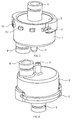
- the relief valve comprises a valve seat, the valve seat is formed with a cavity therein, a water outlet passage and a pressure relief passage are provided on the bottom of the valve seat, both of which communicate with the cavity, the centre of a bottom surface of the cavity is provided with an upward protrusion, and the pressure relief passage runs through the upward protrusion;
- the valve body is fixed inside the cavity, a sealing ring is disposed between the peripheral surface of the valve body and the inner wall of the cavity for sealing the relief valve;
- a water inlet passage communicating with the cavity is provided on the top of the valve body, the bottom of the valve body is formed with a recess, a plurality of apertures are provided in an inner peripheral wall of the recess each communicating with the outer peripheral surface of the valve body, a downward protrusion is provided at the centre of the recess, the water inlet passage runs through the downward protrusion;
- a sealing plate made of flexible material, is
- a projection protruding downward is formed in the centre of the bottom surface of the sealing plate, and when the centre of the sealing plate deforms and sinks, the projection blocks the inlet of the pressure relief passage.
- the arrangement of the projection can better ensure that the sealing plate blocks the inlet of the pressure relief passage when the centre of the sealing plate deforms and sinks.
- the elastic portions are arranged at intervals along the circumference.
- the elastic portions in order to enable the elastic portions to support the sealing plate more stably, there are ten elastic portions, five of which are of a cylindrical shape, the other five of which are of a cuboid shape oriented respectively along the radial direction, moreover, the cylindrical elastic portions and the cuboid elastic portions are arranged at intervals from each other.
- the cylindrical elastic portions have the advantage of good elasticity while the cuboid elastic portions have the advantage of good support.
- the valve body is fixed inside the cavity through a positioning inserting block, the positioning inserting block has a plurality of latches which extend forward and are horizontally arranged at intervals, a plurality of inserting holes are provided in the valve body for receiving the latches, the latches are inserted through an outer wall at one side of the cavity, pass through the inserting holes and finally emerge out of the outer wall on the other side of the cavity.
- the present invention has the following advantages: during normal operation, hot water flows into the water inlet passage, and under the water pressure, the centre of the sealing plate is forced to deform and sink to block the inlet of the pressure relief passage, so that the water flow can only pass in turn through the apertures in the inner peripheral wall of the recess under the valve body and the gap formed between the peripheral surface of the sealing plate and the inner peripheral wall of the cavity, and is then drained from the water outlet passage of the valve seat; during the pressure relief, no hot water flows into the water inlet passage, the sealing plate will return to its original position under the action of the elastic portions and the inlet of the pressure relief passage is opened, so that extra water and pressure inside the brewing system and the pipeline is drained via the pressure relief passage, thus achieving pressure relief; furthermore, this valve configuration not only may realize the pressure relief and split-flow functionality of the solenoid valves, but also has a cost far below that of the solenoid valves; in addition, the function of blocking or unblocking the inlet
- a preferred embodiment of the present invention is shown.
- a relief valve comprises:
- the water inlet passage 5 is connected to the water outlet of a heating boiler of the coffee maker, the water outlet passage 8 is connected to the extraction chamber of the coffee maker via a one-way valve configuration, and the pressure relief passage 3 is connected to the water tank or a garbage box of the coffee maker.
- the hot water heated by the heating boiler flows into the water inlet passage 5, and under the water pressure, the centre of the sealing plate 6 is forced to deform and sink so that the projection 62 blocks the inlet of the pressure relief passage 3, so that the hot water can only pass in turn through the apertures 22 in the inner peripheral wall of the recess 21 under the valve body 2 and the gap X formed between the peripheral surface of the sealing plate 6 and the inner peripheral wall of the cavity 11, and is then drained from the water outlet passage 8 of the valve seat 1.
- the hot water drained pushes open the one-way valve under the water outlet passage 8, and then enters the coffee bag in the extraction chamber to extract coffee.
- the brewing of coffee is completed.
Landscapes
- Engineering & Computer Science (AREA)
- Food Science & Technology (AREA)
- Safety Valves (AREA)
- Lift Valve (AREA)
Claims (5)
- Entlastungsventil, umfassend:einen Ventilsitz (1), wobei der Ventilsitz (1) mit einem darin vorgesehenen Hohlraum (11) ausgebildet ist, wobei ein Wasseraustrittskanal (8) und ein Druckentlastungskanal (3) an der Unterseite des Ventilsitzes (1) vorgesehen sind, wobei beide mit dem Hohlraum (11) in Verbindung stehen, wobei der Mittelpunkt einer Bodenfläche des Hohlraums (11) mit einem nach oben weisenden Vorsprung (12) versehen ist, und der Druckentlastungskanal (3) durch den nach oben weisenden Vorsprung (12) verläuft;wobei der Ventilkörper (2) in dem Hohlraum (11) befestigt ist, wobei ein Dichtungsring (4) zwischen der Randfläche des Ventilkörpers (2) und der inneren Wand des Hohlraums (11) zum Abdichten des Entlastungsventils angeordnet ist; wobei ein Wassereinlasskanal (5), welcher mit dem Hohlraum (11) in Verbindung steht, auf der Oberseite des Ventilkörpers (2) vorgesehen ist, wobei die Unterseite des Ventilkörpers (2) mit einem Rücksprung (21) ausgebildet ist; undwobei eine Dichtungsplatte (6), hergestellt aus einem flexiblen Material, in dem Hohlraum (11) angeordnet und unter dem Ventilkörper (2) positioniert ist, wobei ein Spalt (X) zwischen der Randfläche der Dichtungsplatte (6) und der Innenwand des Hohlraums (11) gebildet wird;dadurch gekennzeichnet,
dass eine Mehrzahl von Durchbrechungen (22) in einer Innenwand des Rücksprungs (21) vorgesehen sind, wobei jede mit der Außenfläche des Ventilkörpers verbunden ist, wobei ein nach unten weisender Vorsprung (23) in dem Mittelpunkt des Rücksprungs (21) vorgesehen ist, wobei der Wassereinlasskanal (5) durch den nach unten weisenden Vorsprung (23) verläuft; und
eine Mehrzahl von nach unten vorstehenden elastischen Abschnitten (61) an der Bodenfläche der Dichtungsplatte (6) vorgesehen ist, wobei die Unterseite jedes elastischen Abschnitts (61) auf der Bodenfläche des Hohlraums (11) abgestützt ist, um zu gewährleisten, dass die Dichtungsplatte (6) immer von dem Einlass des Wasseraustrittskanals (8) getrennt ist; wobei die elastischen Abschnitte (61) in einer Normalsituation die Bodenfläche der Dichtungsplatte (6) von dem Einlass des Druckentlastungskanals (3) abtrennen; wobei, wenn Wasser durch den Wassereintrittskanal (5) fließt, der Mittelpunkt der Dichtungsplatte (6) unter dem Wasserdruck gezwungen ist sich zu deformieren und abzusinken, um den Einlass des Druckentlastungskanals (3) zu blockieren. - Entlastungsventil nach Anspruch 1, dadurch gekennzeichnet, dass ein nach unten vorstehender Vorsprung (62) im Zentrum der Bodenfläche der Dichtungsplatte (6) ausgebildet ist, und dass der Vorsprung (62) den Einlass des Druckentlastungskanals (3) blockiert, wenn der Mittelpunkt der Dichtungsplatte (6) sich deformiert und absinkt.
- Entlastungsventil nach Anspruch 1, dadurch gekennzeichnet, dass die elastischen Abschnitte (61) in Intervallen entlang des Umfangs angeordnet sind.
- Entlastungsventil nach Anspruch 3, dadurch gekennzeichnet, dass zehn elastische Abschnitte (61) vorgesehen sind, von denen fünf eine zylindrische Form aufweisen, die anderen fünf eine Würfelform aufweisen und entlang der radialen Richtung orientiert sind, weitergehend, dass die zylindrischen elastischen Abschnitte (61) und die würfelförmigen elastischen Abschnitte (61) in Intervallen beabstandet voneinander angeordnet sind.
- Entlastungsventil nach Anspruch 1, dadurch gekennzeichnet, dass der Ventilkörper (2) mittels eines positionierenden Einführblocks (7) in dem Hohlraum (11) befestigt ist, wobei der positionierende Einführblock (7) eine Mehrzahl von Riegeln (71) aufweist, welche sich nach vorne erstrecken und horizontal in Intervallen angeordnet sind, wobei eine Mehrzahl von Einführlöchern (24) in dem Ventilkörper (2) vorgesehen sind, um die Riegel (71) aufzunehmen, wobei die Riegel (71) durch eine äußere Wand auf einer Seite des Hohlraums (11) eingeführt werden, durch die Einführlöcher (24) hindurchtreten und schließlich aus der äußeren Wand auf der anderen Seite des Hohlraums (11) heraustreten.
Applications Claiming Priority (2)
| Application Number | Priority Date | Filing Date | Title |
|---|---|---|---|
| CN201210172090.3A CN102835900B (zh) | 2012-05-30 | 2012-05-30 | 一种泄压阀 |
| PCT/CN2013/000018 WO2013177936A1 (zh) | 2012-05-30 | 2013-01-10 | 一种泄压阀 |
Publications (3)
| Publication Number | Publication Date |
|---|---|
| EP2783609A1 EP2783609A1 (de) | 2014-10-01 |
| EP2783609A4 EP2783609A4 (de) | 2015-03-04 |
| EP2783609B1 true EP2783609B1 (de) | 2016-04-27 |
Family
ID=47363827
Family Applications (1)
| Application Number | Title | Priority Date | Filing Date |
|---|---|---|---|
| EP13797283.2A Not-in-force EP2783609B1 (de) | 2012-05-30 | 2013-01-10 | Druckentlastungsventil |
Country Status (3)
| Country | Link |
|---|---|
| EP (1) | EP2783609B1 (de) |
| CN (1) | CN102835900B (de) |
| WO (1) | WO2013177936A1 (de) |
Families Citing this family (7)
| Publication number | Priority date | Publication date | Assignee | Title |
|---|---|---|---|---|
| CN102835900B (zh) * | 2012-05-30 | 2015-01-21 | 宁波全景电器技术有限公司 | 一种泄压阀 |
| CN106859342B (zh) * | 2017-04-17 | 2023-03-31 | 苏州咖博士咖啡系统科技有限公司 | 一种用于咖啡机及饮品机的冲泡器泄压装置 |
| CN107088972A (zh) * | 2017-05-24 | 2017-08-25 | 浙江好亚能源股份有限公司 | 一种使用金钢线快速切割工艺的单晶硅片切片机 |
| CN110123144A (zh) * | 2019-05-07 | 2019-08-16 | 宁波心想科技有限公司 | 背压阀结构及具有该背压阀结构的饮料萃取装置 |
| CN114176400B (zh) * | 2020-09-14 | 2022-11-22 | 宁波方太厨具有限公司 | 变压萃取装置及包括其的咖啡机和茶叶萃取机 |
| CN114176394B (zh) * | 2020-09-14 | 2023-03-31 | 宁波方太厨具有限公司 | 变压萃取装置及包括其的咖啡机和茶叶萃取机 |
| CN113371662B (zh) * | 2021-05-21 | 2022-11-11 | 鹿啄泉矿泉水有限公司 | 空气零接触上水器及保鲜取液系统 |
Family Cites Families (12)
| Publication number | Priority date | Publication date | Assignee | Title |
|---|---|---|---|---|
| US4457330A (en) * | 1983-02-11 | 1984-07-03 | Yardney Corporation | Reversible quick exhaust valve |
| US5176658A (en) * | 1991-05-03 | 1993-01-05 | Sherwood Medical Company | Valve assembly for use in medical devices |
| JP3136795B2 (ja) * | 1992-09-16 | 2001-02-19 | 松下電器産業株式会社 | コーヒー抽出器 |
| DE29618224U1 (de) * | 1996-10-21 | 1998-01-02 | Lai, Xiao Wei, 33619 Bielefeld | Das Kaffeegerät mit Brenngas als Heizenergie |
| US7014076B2 (en) * | 2002-10-15 | 2006-03-21 | Carrier Commercial Registration, Inc. | Syrup delivery system |
| EP1804630B1 (de) * | 2004-09-20 | 2008-08-20 | Koninklijke Philips Electronics N.V. | Getränkeherstellungsvorrichtung mit einer braukammer und druckentlastungsmitteln |
| JP4893315B2 (ja) * | 2007-01-09 | 2012-03-07 | タイガー魔法瓶株式会社 | 飲料容器の栓構造 |
| CN201119773Y (zh) * | 2007-09-12 | 2008-09-24 | 邝坚 | 咖啡机增压泄压阀 |
| CN201627992U (zh) * | 2010-04-13 | 2010-11-10 | 邱家斌 | 减压阀 |
| CN201719074U (zh) * | 2010-05-26 | 2011-01-26 | 应雄峰 | 咖啡机的泄压阀装置 |
| CN202775903U (zh) * | 2012-05-30 | 2013-03-13 | 宁波全景电器技术有限公司 | 一种泄压阀 |
| CN102835900B (zh) * | 2012-05-30 | 2015-01-21 | 宁波全景电器技术有限公司 | 一种泄压阀 |
-
2012
- 2012-05-30 CN CN201210172090.3A patent/CN102835900B/zh not_active Expired - Fee Related
-
2013
- 2013-01-10 EP EP13797283.2A patent/EP2783609B1/de not_active Not-in-force
- 2013-01-10 WO PCT/CN2013/000018 patent/WO2013177936A1/zh not_active Ceased
Also Published As
| Publication number | Publication date |
|---|---|
| CN102835900B (zh) | 2015-01-21 |
| EP2783609A1 (de) | 2014-10-01 |
| WO2013177936A1 (zh) | 2013-12-05 |
| CN102835900A (zh) | 2012-12-26 |
| EP2783609A4 (de) | 2015-03-04 |
Similar Documents
| Publication | Publication Date | Title |
|---|---|---|
| EP2783609A1 (de) | Druckentlastungsventil | |
| ES2587540T3 (es) | Cápsula para productos de infusión | |
| CN103479228B (zh) | 防负压出水嘴 | |
| CN114901110A (zh) | 可重复使用的饮料筒 | |
| JP6208879B2 (ja) | 飲料製造機 | |
| US10485372B2 (en) | Beverage machine | |
| WO2015078096A1 (zh) | 两通泄压阀 | |
| CN105377719A (zh) | 用于可溶制品的具有密封构件的匣盒 | |
| JP5198064B2 (ja) | ブリューチャンバ及び圧力解放手段を有する飲料作製装置 | |
| RU2007140988A (ru) | Устройство и одноразовый контейнер для производства жидких продуктов, в частности напитков | |
| EP3206543B1 (de) | Infustionsgruppe für maschinen zur ausgabe von getränken in form von infusion | |
| CN108700232B (zh) | 具有推入配合式流体耦合器的家用电器系统 | |
| ITBS20130054A1 (it) | Adattatore di capsula o cialda per gruppi di infusione | |
| CN207989809U (zh) | 三通阀和饮品机 | |
| EP3111812B1 (de) | Maschine zur herstellung von brühgetränken und infusionsanordnung | |
| US9826857B2 (en) | Coffee machine with a multi-cellular capsule seat | |
| ITTO20090646A1 (it) | Sistema, capsula, macchina percolatrice e metodo per la preparazione di una bevanda per infusione a concentrazione selezionabile dall'utente | |
| CN204260575U (zh) | 一种二通泄压阀 | |
| CN110662712B (zh) | 具有压力平衡阀的分配头 | |
| KR20160031688A (ko) | 음료 추출 장치 | |
| ES2304571T3 (es) | Dispositivo de infusion para una cafetera automatica. | |
| US20240099500A1 (en) | Drinking recipients with flow regulation means of minimal construction, systems and processes with said drinking recipients | |
| WO2011147844A1 (en) | Infusion assembly of a machine for the production of a beverage and control method for said infusion assembly | |
| CN113811231A (zh) | 用于从胶囊制备液体食物的冲泡室、冲泡单元、设备和系统 | |
| HK1240476A1 (en) | Infusion group for machines for the dispensing of beverages in the form of infusion |
Legal Events
| Date | Code | Title | Description |
|---|---|---|---|
| PUAI | Public reference made under article 153(3) epc to a published international application that has entered the european phase |
Free format text: ORIGINAL CODE: 0009012 |
|
| 17P | Request for examination filed |
Effective date: 20140625 |
|
| AK | Designated contracting states |
Kind code of ref document: A1 Designated state(s): AL AT BE BG CH CY CZ DE DK EE ES FI FR GB GR HR HU IE IS IT LI LT LU LV MC MK MT NL NO PL PT RO RS SE SI SK SM TR |
|
| A4 | Supplementary search report drawn up and despatched |
Effective date: 20150203 |
|
| RIC1 | Information provided on ipc code assigned before grant |
Ipc: A47J 31/44 20060101ALI20150128BHEP Ipc: A47J 31/48 20060101ALI20150128BHEP Ipc: A47J 31/58 20060101ALI20150128BHEP Ipc: A47J 31/46 20060101AFI20150128BHEP |
|
| DAX | Request for extension of the european patent (deleted) | ||
| GRAP | Despatch of communication of intention to grant a patent |
Free format text: ORIGINAL CODE: EPIDOSNIGR1 |
|
| INTG | Intention to grant announced |
Effective date: 20151204 |
|
| GRAS | Grant fee paid |
Free format text: ORIGINAL CODE: EPIDOSNIGR3 |
|
| GRAA | (expected) grant |
Free format text: ORIGINAL CODE: 0009210 |
|
| AK | Designated contracting states |
Kind code of ref document: B1 Designated state(s): AL AT BE BG CH CY CZ DE DK EE ES FI FR GB GR HR HU IE IS IT LI LT LU LV MC MK MT NL NO PL PT RO RS SE SI SK SM TR |
|
| REG | Reference to a national code |
Ref country code: GB Ref legal event code: FG4D |
|
| REG | Reference to a national code |
Ref country code: CH Ref legal event code: EP |
|
| REG | Reference to a national code |
Ref country code: AT Ref legal event code: REF Ref document number: 793785 Country of ref document: AT Kind code of ref document: T Effective date: 20160515 |
|
| REG | Reference to a national code |
Ref country code: IE Ref legal event code: FG4D |
|
| REG | Reference to a national code |
Ref country code: DE Ref legal event code: R096 Ref document number: 602013007170 Country of ref document: DE |
|
| REG | Reference to a national code |
Ref country code: LT Ref legal event code: MG4D |
|
| REG | Reference to a national code |
Ref country code: NL Ref legal event code: MP Effective date: 20160427 |
|
| REG | Reference to a national code |
Ref country code: AT Ref legal event code: MK05 Ref document number: 793785 Country of ref document: AT Kind code of ref document: T Effective date: 20160427 |
|
| PG25 | Lapsed in a contracting state [announced via postgrant information from national office to epo] |
Ref country code: NL Free format text: LAPSE BECAUSE OF FAILURE TO SUBMIT A TRANSLATION OF THE DESCRIPTION OR TO PAY THE FEE WITHIN THE PRESCRIBED TIME-LIMIT Effective date: 20160427 |
|
| PG25 | Lapsed in a contracting state [announced via postgrant information from national office to epo] |
Ref country code: LT Free format text: LAPSE BECAUSE OF FAILURE TO SUBMIT A TRANSLATION OF THE DESCRIPTION OR TO PAY THE FEE WITHIN THE PRESCRIBED TIME-LIMIT Effective date: 20160427 Ref country code: FI Free format text: LAPSE BECAUSE OF FAILURE TO SUBMIT A TRANSLATION OF THE DESCRIPTION OR TO PAY THE FEE WITHIN THE PRESCRIBED TIME-LIMIT Effective date: 20160427 Ref country code: PL Free format text: LAPSE BECAUSE OF FAILURE TO SUBMIT A TRANSLATION OF THE DESCRIPTION OR TO PAY THE FEE WITHIN THE PRESCRIBED TIME-LIMIT Effective date: 20160427 Ref country code: NO Free format text: LAPSE BECAUSE OF FAILURE TO SUBMIT A TRANSLATION OF THE DESCRIPTION OR TO PAY THE FEE WITHIN THE PRESCRIBED TIME-LIMIT Effective date: 20160727 |
|
| PG25 | Lapsed in a contracting state [announced via postgrant information from national office to epo] |
Ref country code: RS Free format text: LAPSE BECAUSE OF FAILURE TO SUBMIT A TRANSLATION OF THE DESCRIPTION OR TO PAY THE FEE WITHIN THE PRESCRIBED TIME-LIMIT Effective date: 20160427 Ref country code: AT Free format text: LAPSE BECAUSE OF FAILURE TO SUBMIT A TRANSLATION OF THE DESCRIPTION OR TO PAY THE FEE WITHIN THE PRESCRIBED TIME-LIMIT Effective date: 20160427 Ref country code: SE Free format text: LAPSE BECAUSE OF FAILURE TO SUBMIT A TRANSLATION OF THE DESCRIPTION OR TO PAY THE FEE WITHIN THE PRESCRIBED TIME-LIMIT Effective date: 20160427 Ref country code: GR Free format text: LAPSE BECAUSE OF FAILURE TO SUBMIT A TRANSLATION OF THE DESCRIPTION OR TO PAY THE FEE WITHIN THE PRESCRIBED TIME-LIMIT Effective date: 20160728 Ref country code: PT Free format text: LAPSE BECAUSE OF FAILURE TO SUBMIT A TRANSLATION OF THE DESCRIPTION OR TO PAY THE FEE WITHIN THE PRESCRIBED TIME-LIMIT Effective date: 20160829 Ref country code: ES Free format text: LAPSE BECAUSE OF FAILURE TO SUBMIT A TRANSLATION OF THE DESCRIPTION OR TO PAY THE FEE WITHIN THE PRESCRIBED TIME-LIMIT Effective date: 20160427 Ref country code: HR Free format text: LAPSE BECAUSE OF FAILURE TO SUBMIT A TRANSLATION OF THE DESCRIPTION OR TO PAY THE FEE WITHIN THE PRESCRIBED TIME-LIMIT Effective date: 20160427 Ref country code: LV Free format text: LAPSE BECAUSE OF FAILURE TO SUBMIT A TRANSLATION OF THE DESCRIPTION OR TO PAY THE FEE WITHIN THE PRESCRIBED TIME-LIMIT Effective date: 20160427 |
|
| PG25 | Lapsed in a contracting state [announced via postgrant information from national office to epo] |
Ref country code: BE Free format text: LAPSE BECAUSE OF FAILURE TO SUBMIT A TRANSLATION OF THE DESCRIPTION OR TO PAY THE FEE WITHIN THE PRESCRIBED TIME-LIMIT Effective date: 20160427 Ref country code: IT Free format text: LAPSE BECAUSE OF FAILURE TO SUBMIT A TRANSLATION OF THE DESCRIPTION OR TO PAY THE FEE WITHIN THE PRESCRIBED TIME-LIMIT Effective date: 20160427 |
|
| REG | Reference to a national code |
Ref country code: DE Ref legal event code: R097 Ref document number: 602013007170 Country of ref document: DE |
|
| PG25 | Lapsed in a contracting state [announced via postgrant information from national office to epo] |
Ref country code: DK Free format text: LAPSE BECAUSE OF FAILURE TO SUBMIT A TRANSLATION OF THE DESCRIPTION OR TO PAY THE FEE WITHIN THE PRESCRIBED TIME-LIMIT Effective date: 20160427 Ref country code: RO Free format text: LAPSE BECAUSE OF FAILURE TO SUBMIT A TRANSLATION OF THE DESCRIPTION OR TO PAY THE FEE WITHIN THE PRESCRIBED TIME-LIMIT Effective date: 20160427 Ref country code: EE Free format text: LAPSE BECAUSE OF FAILURE TO SUBMIT A TRANSLATION OF THE DESCRIPTION OR TO PAY THE FEE WITHIN THE PRESCRIBED TIME-LIMIT Effective date: 20160427 Ref country code: CZ Free format text: LAPSE BECAUSE OF FAILURE TO SUBMIT A TRANSLATION OF THE DESCRIPTION OR TO PAY THE FEE WITHIN THE PRESCRIBED TIME-LIMIT Effective date: 20160427 Ref country code: SK Free format text: LAPSE BECAUSE OF FAILURE TO SUBMIT A TRANSLATION OF THE DESCRIPTION OR TO PAY THE FEE WITHIN THE PRESCRIBED TIME-LIMIT Effective date: 20160427 |
|
| PG25 | Lapsed in a contracting state [announced via postgrant information from national office to epo] |
Ref country code: SM Free format text: LAPSE BECAUSE OF FAILURE TO SUBMIT A TRANSLATION OF THE DESCRIPTION OR TO PAY THE FEE WITHIN THE PRESCRIBED TIME-LIMIT Effective date: 20160427 |
|
| PLBE | No opposition filed within time limit |
Free format text: ORIGINAL CODE: 0009261 |
|
| STAA | Information on the status of an ep patent application or granted ep patent |
Free format text: STATUS: NO OPPOSITION FILED WITHIN TIME LIMIT |
|
| 26N | No opposition filed |
Effective date: 20170130 |
|
| PG25 | Lapsed in a contracting state [announced via postgrant information from national office to epo] |
Ref country code: SI Free format text: LAPSE BECAUSE OF FAILURE TO SUBMIT A TRANSLATION OF THE DESCRIPTION OR TO PAY THE FEE WITHIN THE PRESCRIBED TIME-LIMIT Effective date: 20160427 |
|
| REG | Reference to a national code |
Ref country code: CH Ref legal event code: PL |
|
| GBPC | Gb: european patent ceased through non-payment of renewal fee |
Effective date: 20170110 |
|
| PG25 | Lapsed in a contracting state [announced via postgrant information from national office to epo] |
Ref country code: MC Free format text: LAPSE BECAUSE OF FAILURE TO SUBMIT A TRANSLATION OF THE DESCRIPTION OR TO PAY THE FEE WITHIN THE PRESCRIBED TIME-LIMIT Effective date: 20160427 |
|
| REG | Reference to a national code |
Ref country code: FR Ref legal event code: ST Effective date: 20170929 |
|
| PG25 | Lapsed in a contracting state [announced via postgrant information from national office to epo] |
Ref country code: CH Free format text: LAPSE BECAUSE OF NON-PAYMENT OF DUE FEES Effective date: 20170131 Ref country code: FR Free format text: LAPSE BECAUSE OF NON-PAYMENT OF DUE FEES Effective date: 20170131 Ref country code: LI Free format text: LAPSE BECAUSE OF NON-PAYMENT OF DUE FEES Effective date: 20170131 |
|
| REG | Reference to a national code |
Ref country code: IE Ref legal event code: MM4A |
|
| PG25 | Lapsed in a contracting state [announced via postgrant information from national office to epo] |
Ref country code: LU Free format text: LAPSE BECAUSE OF NON-PAYMENT OF DUE FEES Effective date: 20170110 Ref country code: GB Free format text: LAPSE BECAUSE OF NON-PAYMENT OF DUE FEES Effective date: 20170110 |
|
| PG25 | Lapsed in a contracting state [announced via postgrant information from national office to epo] |
Ref country code: IE Free format text: LAPSE BECAUSE OF NON-PAYMENT OF DUE FEES Effective date: 20170110 |
|
| PG25 | Lapsed in a contracting state [announced via postgrant information from national office to epo] |
Ref country code: MT Free format text: LAPSE BECAUSE OF NON-PAYMENT OF DUE FEES Effective date: 20170110 |
|
| PG25 | Lapsed in a contracting state [announced via postgrant information from national office to epo] |
Ref country code: AL Free format text: LAPSE BECAUSE OF FAILURE TO SUBMIT A TRANSLATION OF THE DESCRIPTION OR TO PAY THE FEE WITHIN THE PRESCRIBED TIME-LIMIT Effective date: 20160427 |
|
| PG25 | Lapsed in a contracting state [announced via postgrant information from national office to epo] |
Ref country code: HU Free format text: LAPSE BECAUSE OF FAILURE TO SUBMIT A TRANSLATION OF THE DESCRIPTION OR TO PAY THE FEE WITHIN THE PRESCRIBED TIME-LIMIT; INVALID AB INITIO Effective date: 20130110 |
|
| PG25 | Lapsed in a contracting state [announced via postgrant information from national office to epo] |
Ref country code: BG Free format text: LAPSE BECAUSE OF FAILURE TO SUBMIT A TRANSLATION OF THE DESCRIPTION OR TO PAY THE FEE WITHIN THE PRESCRIBED TIME-LIMIT Effective date: 20160427 |
|
| PG25 | Lapsed in a contracting state [announced via postgrant information from national office to epo] |
Ref country code: CY Free format text: LAPSE BECAUSE OF NON-PAYMENT OF DUE FEES Effective date: 20160427 |
|
| PG25 | Lapsed in a contracting state [announced via postgrant information from national office to epo] |
Ref country code: MK Free format text: LAPSE BECAUSE OF FAILURE TO SUBMIT A TRANSLATION OF THE DESCRIPTION OR TO PAY THE FEE WITHIN THE PRESCRIBED TIME-LIMIT Effective date: 20160427 |
|
| PG25 | Lapsed in a contracting state [announced via postgrant information from national office to epo] |
Ref country code: TR Free format text: LAPSE BECAUSE OF FAILURE TO SUBMIT A TRANSLATION OF THE DESCRIPTION OR TO PAY THE FEE WITHIN THE PRESCRIBED TIME-LIMIT Effective date: 20160427 |
|
| PG25 | Lapsed in a contracting state [announced via postgrant information from national office to epo] |
Ref country code: IS Free format text: LAPSE BECAUSE OF FAILURE TO SUBMIT A TRANSLATION OF THE DESCRIPTION OR TO PAY THE FEE WITHIN THE PRESCRIBED TIME-LIMIT Effective date: 20160827 |
|
| PGFP | Annual fee paid to national office [announced via postgrant information from national office to epo] |
Ref country code: DE Payment date: 20240125 Year of fee payment: 12 |
|
| REG | Reference to a national code |
Ref country code: DE Ref legal event code: R119 Ref document number: 602013007170 Country of ref document: DE |
|
| PG25 | Lapsed in a contracting state [announced via postgrant information from national office to epo] |
Ref country code: DE Free format text: LAPSE BECAUSE OF NON-PAYMENT OF DUE FEES Effective date: 20250801 |