EP2783768A1 - Procédé de prélèvement de pièces à partir d'une machine d'usinage et machine d'usinage - Google Patents
Procédé de prélèvement de pièces à partir d'une machine d'usinage et machine d'usinage Download PDFInfo
- Publication number
- EP2783768A1 EP2783768A1 EP20140155745 EP14155745A EP2783768A1 EP 2783768 A1 EP2783768 A1 EP 2783768A1 EP 20140155745 EP20140155745 EP 20140155745 EP 14155745 A EP14155745 A EP 14155745A EP 2783768 A1 EP2783768 A1 EP 2783768A1
- Authority
- EP
- European Patent Office
- Prior art keywords
- workpiece
- removal device
- workpieces
- processing
- holding elements
- Prior art date
- Legal status (The legal status is an assumption and is not a legal conclusion. Google has not performed a legal analysis and makes no representation as to the accuracy of the status listed.)
- Granted
Links
Images


Classifications
-
- B—PERFORMING OPERATIONS; TRANSPORTING
- B26—HAND CUTTING TOOLS; CUTTING; SEVERING
- B26D—CUTTING; DETAILS COMMON TO MACHINES FOR PERFORATING, PUNCHING, CUTTING-OUT, STAMPING-OUT OR SEVERING
- B26D7/00—Details of apparatus for cutting, cutting-out, stamping-out, punching, perforating, or severing by means other than cutting
- B26D7/18—Means for removing cut-out material or waste
- B26D7/1845—Means for removing cut-out material or waste by non mechanical means
- B26D7/1863—Means for removing cut-out material or waste by non mechanical means by suction
-
- B—PERFORMING OPERATIONS; TRANSPORTING
- B21—MECHANICAL METAL-WORKING WITHOUT ESSENTIALLY REMOVING MATERIAL; PUNCHING METAL
- B21D—WORKING OR PROCESSING OF SHEET METAL OR METAL TUBES, RODS OR PROFILES WITHOUT ESSENTIALLY REMOVING MATERIAL; PUNCHING METAL
- B21D43/00—Feeding, positioning or storing devices combined with, or arranged in, or specially adapted for use in connection with, apparatus for working or processing sheet metal, metal tubes or metal profiles; Associations therewith of cutting devices
- B21D43/02—Advancing work in relation to the stroke of the die or tool
- B21D43/04—Advancing work in relation to the stroke of the die or tool by means in mechanical engagement with the work
- B21D43/10—Advancing work in relation to the stroke of the die or tool by means in mechanical engagement with the work by grippers
- B21D43/105—Manipulators, i.e. mechanical arms carrying a gripper element having several degrees of freedom
-
- B—PERFORMING OPERATIONS; TRANSPORTING
- B26—HAND CUTTING TOOLS; CUTTING; SEVERING
- B26D—CUTTING; DETAILS COMMON TO MACHINES FOR PERFORATING, PUNCHING, CUTTING-OUT, STAMPING-OUT OR SEVERING
- B26D7/00—Details of apparatus for cutting, cutting-out, stamping-out, punching, perforating, or severing by means other than cutting
- B26D7/18—Means for removing cut-out material or waste
-
- B—PERFORMING OPERATIONS; TRANSPORTING
- B26—HAND CUTTING TOOLS; CUTTING; SEVERING
- B26D—CUTTING; DETAILS COMMON TO MACHINES FOR PERFORATING, PUNCHING, CUTTING-OUT, STAMPING-OUT OR SEVERING
- B26D7/00—Details of apparatus for cutting, cutting-out, stamping-out, punching, perforating, or severing by means other than cutting
- B26D7/27—Means for performing other operations combined with cutting
- B26D7/32—Means for performing other operations combined with cutting for conveying or stacking cut product
-
- Y—GENERAL TAGGING OF NEW TECHNOLOGICAL DEVELOPMENTS; GENERAL TAGGING OF CROSS-SECTIONAL TECHNOLOGIES SPANNING OVER SEVERAL SECTIONS OF THE IPC; TECHNICAL SUBJECTS COVERED BY FORMER USPC CROSS-REFERENCE ART COLLECTIONS [XRACs] AND DIGESTS
- Y10—TECHNICAL SUBJECTS COVERED BY FORMER USPC
- Y10T—TECHNICAL SUBJECTS COVERED BY FORMER US CLASSIFICATION
- Y10T83/00—Cutting
- Y10T83/04—Processes
- Y10T83/0448—With subsequent handling [i.e., of product]
-
- Y—GENERAL TAGGING OF NEW TECHNOLOGICAL DEVELOPMENTS; GENERAL TAGGING OF CROSS-SECTIONAL TECHNOLOGIES SPANNING OVER SEVERAL SECTIONS OF THE IPC; TECHNICAL SUBJECTS COVERED BY FORMER USPC CROSS-REFERENCE ART COLLECTIONS [XRACs] AND DIGESTS
- Y10—TECHNICAL SUBJECTS COVERED BY FORMER USPC
- Y10T—TECHNICAL SUBJECTS COVERED BY FORMER US CLASSIFICATION
- Y10T83/00—Cutting
- Y10T83/04—Processes
- Y10T83/0448—With subsequent handling [i.e., of product]
- Y10T83/0467—By separating products from each other
-
- Y—GENERAL TAGGING OF NEW TECHNOLOGICAL DEVELOPMENTS; GENERAL TAGGING OF CROSS-SECTIONAL TECHNOLOGIES SPANNING OVER SEVERAL SECTIONS OF THE IPC; TECHNICAL SUBJECTS COVERED BY FORMER USPC CROSS-REFERENCE ART COLLECTIONS [XRACs] AND DIGESTS
- Y10—TECHNICAL SUBJECTS COVERED BY FORMER USPC
- Y10T—TECHNICAL SUBJECTS COVERED BY FORMER US CLASSIFICATION
- Y10T83/00—Cutting
- Y10T83/202—With product handling means
- Y10T83/2092—Means to move, guide, or permit free fall or flight of product
- Y10T83/2183—Product mover including gripper means
-
- Y—GENERAL TAGGING OF NEW TECHNOLOGICAL DEVELOPMENTS; GENERAL TAGGING OF CROSS-SECTIONAL TECHNOLOGIES SPANNING OVER SEVERAL SECTIONS OF THE IPC; TECHNICAL SUBJECTS COVERED BY FORMER USPC CROSS-REFERENCE ART COLLECTIONS [XRACs] AND DIGESTS
- Y10—TECHNICAL SUBJECTS COVERED BY FORMER USPC
- Y10T—TECHNICAL SUBJECTS COVERED BY FORMER US CLASSIFICATION
- Y10T83/00—Cutting
- Y10T83/202—With product handling means
- Y10T83/2092—Means to move, guide, or permit free fall or flight of product
- Y10T83/2183—Product mover including gripper means
- Y10T83/2185—Suction gripper
Definitions
- the invention relates to a method for removing workpieces from a processing machine and a processing machine, wherein the workpieces are made of a plate-shaped material which rests on a workpiece support in the processing machine, with a processing device by cutting.
- a processing of the plate-shaped material is carried out so far each individually a removal of the produced workpiece from the processing area, which is removed after a free cutting with a removal device from the processing area and fed to an unloading station.
- the required cycle time for the removal and unloading of the cut-free workpiece by means of the removal device is usually greater than the processing time for cutting the subsequent workpiece. This leads to waiting times and to a deterioration in the degree of automation, especially for small workpiece parts.
- the invention has for its object to provide a method for removing workpieces from a processing machine and a processing machine by which an increase in the cycle time and thus an improvement in productivity with a particular skeletal free processing of the plate-shaped material is made possible.
- This object is achieved by a method in which after removal cutting of the first workpiece, a removal device is positioned with a holding element in a receiving position for the first workpiece, the workpiece receives and then the removal device is moved to a waiting position outside the receiving position and adjacent to the processing area in that, after the cutting of the further workpiece, the removal device is moved from the waiting position into the receiving position in order to engage with a further retaining element of the Removal device to remove the other workpiece and then moved back from the receiving position to the waiting position.
- the removal device is moved after receiving at least two workpieces in succession or after the processing of the plate-shaped material in an unloading station.
- the cycle times for the removal of the workpieces from the processing area can be substantially shortened, since the removal device remains adjacent as long as in a waiting position to the processing area until a plurality or all holding elements of the removal device, which are provided for receiving workpieces, carry a workpiece, in order subsequently to carry out only one movement movement between the waiting position and the unloading station in order to deposit a plurality or all of the picked-up workpieces in the unloading station.
- a multi-part removal is created directly with respect to the processing area of the processing machine, in which the removal device is repeatedly moved between the receiving position of the processing machine in the processing area and the adjacent waiting position and moves only after receiving several workpieces or after complete processing of the plate-shaped material in the unloading.
- a preferred embodiment of the method provides that the machined workpiece by cutting cutting leaving a residual compound cut and the removal device is moved into the receiving position to the workpiece, so that subsequently carried out a fixation of the workpiece to be removed with the holding element of the removal device and subsequently the workpiece is cut out of the processing area before removal. This allows a secure gripping of the workpiece with the holding element of the removal device and a safe removal from the processing area.
- the removal device with the picked workpiece is preferably raised in the Z direction after the free cutting and moved into a subsequent receiving position for the subsequent workpiece or in the waiting position in the X direction, Y direction or X / Y direction and the processing for Production of the subsequent workpiece continued.
- short cycle times can be achieved.
- a further preferred alternative of the method provides that the travel path of the removal device is adapted to the subsequent receiving position on the X-axis dimension of the subsequent workpiece. As a result, a reduction of the travel distance can also be achieved.
- a further alternative embodiment of the method provides that the travel path of the removal device is oriented in the subsequent receiving position on the grid dimension of the holding elements of the removal device. In this way it can be ensured that in each case the free holding element is supplied with a short movement to the workpiece produced last and a safe removal is made possible.
- the workpieces are preferably produced in succession along one side edge of the plate-shaped material, which faces outwards relative to the preferably stationary processing device, and the workpieces are received in succession and in the same order by the holding elements of the removal device.
- the workpieces can be stored in an unloading station in the same order, whereby an assignment and sorting of the individual workpieces is simplified, if they differ, for example, in size from each other.
- a further preferred embodiment of the method provides that the Traversing between the waiting position and the receiving position by the pitch of the holding elements and the size of the workpieces is determined. If, for example, a removal device with holding elements has the same longitudinal extent as the plate-shaped material, the plate-shaped material is transported in the X direction by the same path as the removal device is moved.
- the workpieces are preferably all deposited simultaneously in the unloading station or are preferably deposited one after the other, preferably on a stack.
- the common storage of all workpieces simultaneously has a time advantage over the stacking of the workpieces.
- the cut-free workpieces are stored after removal in an intermediate buffer of the removal device.
- a plurality of workpieces can be stored in a relatively small-sized removal device.
- the successive separation cutting of the workpieces is preferably carried out by a skeleton-free processing of the plate-shaped material.
- This is a particularly preferred embodiment and particularly useful if the removal device has holding elements that can not be moved individually in the Z-axis. This skeleton-free processing may also be required if collision monitoring in the Z direction is not possible.
- the object underlying the invention is further achieved by a processing machine for processing a plate-shaped material having a removal device with a plurality of holding elements, which successively the workpieces from a processing area of the machine removably and in a waiting position adjacent to the processing area positioned and the holding elements sequentially can be controlled to accommodate the other workpieces.
- the removal device can be moved several times from a waiting position into a receiving position, in order to receive a further workpiece after the respective cutting of the workpiece until all picking positions of the picking device are occupied, in order subsequently to transfer the picked-up workpieces together to the unloading station.
- the removal device has at least two holding elements arranged one behind the other in a row.
- a narrow and elongate removal device can be provided, which can extend over the entire length of the plate-shaped material, so that all workpieces that are processed in series one behind the other can be picked up and transferred to the unloading station.
- the removal device has two or more parallel aligned rows of holding elements.
- the rear row of holding elements arranged on the side edge of the plate-shaped material is first of all driven to pick up the workpiece and then the next front row or the front row of holding elements is moved.
- the holding elements of the removal device are preferably equipped as suction grippers or vacuum suction grippers.
- a preferred embodiment of the processing machine provides that at least one holding element of the removal device along the Z-axis is movable. Preferably, all holding elements of the removal device are individually movable. This has the advantage that the removal device can be positioned in the receiving position above the workpiece to be removed and only the holding element is lowered, which removes the workpiece. As a result, both a skeleton-free processing and a processing with skeleton grid is possible, especially in the case of processing with skeletons due to this configuration, the skeleton grid does not interfere with the removal.
- a further preferred embodiment of the invention provides that the removal device has a discharge device or a handling robot, through which the workpieces are removed and fed to the temporary storage.
- a single removal by means of the handling robot can be a good accessibility to Removal of the workpieces to be given in the receiving position.
- a simple transfer of the workpieces can be done in an intermediate buffer.
- an intermediate buffer may be formed above a suction frame for the removal device.
- the removal device preferably has an intermediate buffer. As a result, the number of travel paths between the waiting position and the unloading and loading position can be further reduced.
- the removal device of the processing machine preferably has a chain or a band with a plurality of suction cups arranged thereon.
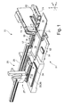
- FIG. 1 is shown in perspective a processing machine 11, which is designed for example as a punching machine.
- a processing machine 11 which is designed for example as a punching machine.
- a preferably stationary machining device 21 is provided with a punching head 14 and with a punch, not shown.
- a laser punching machine can be used, in which adjacent to the punching head 14, a laser processing head is provided.
- the workpiece 12 to be machined rests on a workpiece support 16 during workpiece machining.
- the workpiece 12 is held during machining with a holding device 17, which preferably comprises clamps 18, and can be moved relative to the punching head 14 in the X direction of the workpiece plane (X / Y plane) by means of a conventional linear drive 19 indicated by an arrow , In the Y-direction of the workpiece plane, the workpiece 12 can be moved by the workpiece support 16 is moved together with the holding device 17 relative to a base 24 on which the workpiece support 16 is mounted by means of an indicated by an arrow conventional linear actuator 20.
- the workpiece 12 can be moved in this way in the X and Y direction relative to the punching head 14, so that the respectively to be machined portion of the workpiece 12 can be positioned in the processing region of the punching head 14, if they are present.
- the processing area is between the punching head 14 and a punching die, not shown, which is replaceable. Accordingly, a laser optical system can be arranged in the stationary processing region of the laser processing head in a laser punching machine.
- a handling device 26 is provided on an end side, which may include a removal device 27 along at least one linear axis 28 from a loading and unloading position 29, 30 for the plate-shaped material 12 in a removal position 32 and waiting position 32nd according to Figure 2c is movable.
- the removal device 27 comprises a plurality of holding elements 34, which can be designed as a magnetic vacuum, vacuum suction or Elektroadophsionssauger.
- a holding element 34 is provided with a plurality of individual suckers, each of which forms the holding element 34 associated with each other ( Figure 2c ).
- the holding elements 34 can in at least one other axis, ie in a Y and / or Z-axis, along the XYZ coordinate system, which in FIG. 1 is shown, with at least one linear drive driven to be driven.
- FIG. 2a are schematically enlarged, the plate-shaped workpiece 12 and the holding device 17 shown with the brackets 18 which receive the plate-shaped workpiece 12.
- the punching head 14 is shown in a starting position. This workpiece 12 rests on the workpiece support 16, which - like the other components of the processing machine 11 - are not shown.
- the plate-shaped material 12 is moved such that the punching head 14 is initially located at the position 38, from there to introduce a first cut in the plate-shaped material 12, which ends in position 39. Subsequently, the plate-shaped material 12 is moved such that the punching head 14 is in position 41 to perform from there a second cut, which ends in position 42. This leaves a remaining connection 43 for a Final Cut.
- the removal device 27 is from a loading or unloading position 29, 30 or preferably from a waiting position 32, the in Figure 2c is shown and already during the first cuts for the production of the workpiece 36 has been taken, moved into a receiving position 45, so that a holding element, which comprises, for example, three suckers, positioned to the workpiece 36 and is gripped by the holding member 34.
- a holding element which comprises, for example, three suckers
- the removal device 27 is lifted at least slightly in the Z direction and / or out in the Y direction out of the receiving position 45, so that the removal device 27 in turn the in Figure 2c shown waiting position 32 occupies.
- the length of the plate-shaped material 12 preferably corresponds to the length of the removal device 27 or the holding elements 34 lined up with one another, so that a row of workpieces 36 arranged one behind the other can be picked up by the removal device 27.
- the removal device 27 can be moved via the handling device 26 from the waiting position 32 in an unloading 51, which is formed for example by a magazine 52, which is positioned below the workpiece holder 16.
- the Unloading station 51 may also be positioned adjacent to the loading and unloading station 29, 30 in the working area of the linear axis 28, which can be operated via the handling device 26.
- the workpieces 36 can be stored stacked, for example.
- the workpieces can also be deposited simultaneously on the magazine 52, in the manner in which they are removed from the removal device 27 from the respective receiving position 45.
- two successively arranged rows of holding elements 34 are provided.
- a frame receiving the holding elements 34 can be provided, which can be rotated through 180 °, so that after the filling of the first row of holding elements 34, the second row of holding elements 34 is subsequently filled.
- the above-described removal device 27 may advantageously have holding elements 34, which consists of one or more suckers 35, wherein the individual holding elements 34 in the Z direction individually or in groups can be moved and controlled. This allows an analogous operation as the above-described operation.
- a machining for the production of the workpieces 36 with a remaining skeletal grid done. Due to the mobility of the holding elements 34 along the Z-axis, the suckers 35 can be lowered onto the workpiece 36 to be removed.
- a removal of workpieces 36 during processing can be carried out with a remaining skeleton without the holding elements 34 being movable in the Z direction.
- the suction force of the suckers 35 or the magnetic force of a magnetic gripper can bridge a remaining distance which remains in a positioning of the removal device 27 with an already recorded workpiece 36 for removal of another workpiece 36 ', since a complete lowering of the removal device 27 due to the remaining skeleton not is possible.
- FIG. 3 an alternative embodiment is shown to allow a multi-part removal with the removal device 27 in front of the punching head 14.
- the removal device 27 In order to be able to move the workpieces 36 on the punching head 14 in the X direction, it is proposed to equip the removal device 27 with a travel axis in the Y direction, so that the removal device 27 can also be positioned past the processing device 21 in order to enable a multi-part removal ,
- the movement of the removal device 27 can analogously to in the FIGS. 2a to 2c Traversing movement described done.
- the holding elements 34 may be formed in this embodiment, for example, from a group of suckers 35, which may be arranged at a distance from each other.
- FIG. 4 a further alternative embodiment for a Entladestraategie is shown, in which a receiving position 45 and discharge position is provided adjacent to the punching head 14.
- the holding elements 34 are at a distance from one another in order to form a free space or a recess 55 therebetween, which makes it possible for at least partial immersion of the punching head 14 into the recess 55 when the removal device 27 moves in the Y direction.
- the holding elements 34 can be positioned laterally relative to the punching head 14 in order to remove workpieces 36, 36 '.
- the removal device 27 is moved in the Y direction, wherein a small movement can be superimposed in the Z direction or initially takes place and then merges into a Y direction.
- FIG. 5 a schematic side view of an alternative embodiment of the removal device 27 is shown.
- This removal device has, instead of a plurality of arranged in a plane holding elements 34 with suction 35 a circulating belt or chain 61 on which a plurality of suckers 35 are arranged.
- This removal device 27 is transferred into the receiving position 45, so that the next free vacuum cleaner 35 can remove the workpiece 36. Subsequently, the removal device 27 is again moved to the waiting position 32 and the chain 61 expertiseergetaktet in the direction of arrow 62, so that the next free vacant 35 is provided for recording.
- This arrangement has the advantage that in turn an intermediate buffer 67 has been created by such a chain 61 with suckers 35 or grippers.
- such a chain 61 can be formed narrow with 35 arranged thereon suckers.
- a plurality of chains 61 with suckers 35 arranged thereon are arranged in series next to one another and form a removal device 27, which are used successively.
- FIG. 6 a further alternative embodiment of the removal device 27 is shown.
- This embodiment of the removal device 27 comprises a holding element 34, which is designed as a suction frame, for example, to remove the plate-shaped material 12 from the loading position 29 and supply the processing area.
- an unloading device or a handling robot 66 is arranged on the suction frame, which is designed, for example, as a single or multi-axis robot, which comprises a gripper.
- the gripper can be designed as a suction gripper or magnetic gripper. After removal of the workpiece 36 this is the handling robot 66 in the intermediate buffer 67th converted. This can be provided for example by a storage area on the back or top of the suction frame of the holding elements 34 for receiving the produced workpieces 36.
- the two embodiments of the removal devices 27 are suitable both for a skeleton-free processing and a processing of the plate-like material in which a skeleton remains, which leads out of the processing area after the production of the workpieces or crushed already after the production of the respective workpiece and a Opening in the workpiece support 16 is continuously removed.
Landscapes
- Engineering & Computer Science (AREA)
- Mechanical Engineering (AREA)
- Life Sciences & Earth Sciences (AREA)
- Forests & Forestry (AREA)
- Laser Beam Processing (AREA)
- Feeding Of Articles By Means Other Than Belts Or Rollers (AREA)
- Details Of Cutting Devices (AREA)
- Feeding Of Workpieces (AREA)
Applications Claiming Priority (1)
| Application Number | Priority Date | Filing Date | Title |
|---|---|---|---|
| DE201310103121 DE102013103121A1 (de) | 2013-03-27 | 2013-03-27 | Verfahren zum Entnehmen von Werkstücken aus einer Bearbeitungsmaschine sowie Bearbeitungsmaschine |
Publications (2)
| Publication Number | Publication Date |
|---|---|
| EP2783768A1 true EP2783768A1 (fr) | 2014-10-01 |
| EP2783768B1 EP2783768B1 (fr) | 2016-06-22 |
Family
ID=50137514
Family Applications (1)
| Application Number | Title | Priority Date | Filing Date |
|---|---|---|---|
| EP14155745.4A Active EP2783768B1 (fr) | 2013-03-27 | 2014-02-19 | Procédé de prélèvement de pièces à partir d'une machine d'usinage et machine d'usinage |
Country Status (4)
| Country | Link |
|---|---|
| US (1) | US9550307B2 (fr) |
| EP (1) | EP2783768B1 (fr) |
| JP (1) | JP6426361B2 (fr) |
| DE (1) | DE102013103121A1 (fr) |
Families Citing this family (15)
| Publication number | Priority date | Publication date | Assignee | Title |
|---|---|---|---|---|
| DE102013214844A1 (de) * | 2013-07-30 | 2015-02-05 | Trumpf Sachsen Gmbh | Vorrichtung zum Handhaben von Werkstücken sowie maschinelle Anordnung mit einer derartigen Vorrichtung |
| DE102016106067A1 (de) | 2016-04-04 | 2017-10-05 | Trumpf Werkzeugmaschinen Gmbh + Co. Kg | Verfahren und Bearbeitungsmaschine zum schneidenden Bearbeiten von plattenförmigen oder stabförmigen Werkstücken |
| CN106040895B (zh) * | 2016-07-15 | 2019-06-04 | 祥鑫科技股份有限公司 | 小型气动传送机械手 |
| CN109262143A (zh) * | 2017-07-12 | 2019-01-25 | 上海宝钢工业技术服务有限公司 | 薄板带钢检测样品的智能化加工系统 |
| CN109015856A (zh) * | 2018-09-10 | 2018-12-18 | 闳诚科技有限公司 | 一种用于磁性金属箔板裁剪的裁切机 |
| DE102019115634B3 (de) * | 2019-06-07 | 2020-12-03 | Bystronic Laser Ag | Sortiersystem für eine Werkzeugmaschine, Werkzeugmaschine und Verfahren zum Sortieren von Schnittteilen |
| DE102019115559B4 (de) * | 2019-06-07 | 2021-10-07 | Bystronic Laser Ag | Greifsystem zum Greifen von verarbeiteten Teilen und Verfahren zur Detektion ob ein verarbeitetes Teil geschnitten wurde |
| CN112007985A (zh) * | 2020-09-14 | 2020-12-01 | 江苏鸿基金属制品有限公司 | 一种汽车模金属冲压零件的翻孔加工模具 |
| CN113020416B (zh) * | 2021-03-06 | 2022-11-11 | 钟小阳 | 一种板材冲孔定向卸料装置及其实施方法 |
| CN115194864B (zh) * | 2021-04-08 | 2024-11-15 | 卡尔欧根菲舍尔有限责任公司 | 用于从材料带切割窄条带的切割设备 |
| DE102022127169B3 (de) * | 2022-10-18 | 2024-03-28 | TRUMPF Werkzeugmaschinen SE + Co. KG | Entladeverfahren und maschinelle Entladeanordnung zum Entladen eines Bearbeitungsprodukts einer Werkstückbearbeitung sowie Fertigungsverfahren und maschinelle Fertigungsanordnung |
| DE102022212462A1 (de) | 2022-11-22 | 2024-05-23 | J.Schmalz Gmbh | Sequientelles Entnahmeverfahren und Verfahren zum Entnehmen von Werkstücken mit mehreren Entnahmezyklen |
| DE102023124875A1 (de) | 2023-09-14 | 2025-03-20 | TRUMPF Werkzeugmaschinen SE + Co. KG | Verfahren zum Herstellen von mehreren Werkstücken, Computerprogramm, Vorrichtung zur Datenverarbeitung und Werkzeugmaschine |
| DE102023129990A1 (de) | 2023-10-30 | 2025-04-30 | TRUMPF Werkzeugmaschinen SE + Co. KG | Maschinelle Anordnung und Verfahren zur Handhabung von zumindest einem plattenförmigen Werkstück |
| JP7778211B1 (ja) * | 2024-11-27 | 2025-12-01 | ヤマザキマザック株式会社 | ワーク搬送装置、および、レーザ加工システム |
Citations (5)
| Publication number | Priority date | Publication date | Assignee | Title |
|---|---|---|---|---|
| EP0128487A1 (fr) * | 1983-06-09 | 1984-12-19 | Trumpf GmbH & Co | Machine-outil avec un magasin stationnaire |
| US4930976A (en) * | 1989-03-28 | 1990-06-05 | Alliance Automations Systems, Inc. | Multiple gripper turret for part handling devices and method of handling parts |
| DE102006023885A1 (de) * | 2006-03-31 | 2007-10-04 | J. Schmalz Gmbh | Autonome Schlüsselkomponenten für flexible Vakuumgreifer |
| EP1967301A1 (fr) * | 2007-03-06 | 2008-09-10 | Trumpf Sachsen GmbH | Agencement mécanique destiné au traitement de pièces à usiner de type plaques à l'aide d'un dispositif de traitement tout comme avec un dispositif de manipulation pour produits de traitement |
| US20100040450A1 (en) * | 2008-08-15 | 2010-02-18 | Amf Automation Technologies, Inc. | Programmable Zoned End Effector |
Family Cites Families (21)
| Publication number | Priority date | Publication date | Assignee | Title |
|---|---|---|---|---|
| LU51862A1 (fr) * | 1965-09-02 | 1966-10-31 | ||
| US3728921A (en) * | 1971-04-01 | 1973-04-24 | Hayseen Mfg Co | Apparatus for cutting a web into sheets and positioning the sheets |
| US3877332A (en) * | 1972-09-07 | 1975-04-15 | Hurco Mfg Co Inc | Automatic shearing method |
| JPS63196419A (ja) * | 1987-02-06 | 1988-08-15 | Fuji Photo Film Co Ltd | 平面状部材の整列方法および装置 |
| JP2541829B2 (ja) * | 1987-09-30 | 1996-10-09 | ぺんてる株式会社 | ロボットのマトリックス状ハンドへのワ―ク供給方法 |
| US5189934A (en) * | 1988-06-02 | 1993-03-02 | Eton Construction Ab | Apparatus for cutting and removing portions from a material web |
| JP2872418B2 (ja) * | 1991-02-22 | 1999-03-17 | 株式会社アマダメトレックス | 製品分離、搬出用ハンドリングロボット |
| JPH0597272A (ja) * | 1991-10-03 | 1993-04-20 | Amada Co Ltd | ワーク取出し搬送方法 |
| US5463921A (en) * | 1993-03-05 | 1995-11-07 | The Charles Stark Draper Laboratory, Inc. | Method and apparatus for automated handling of cut material |
| US5883357A (en) * | 1996-03-25 | 1999-03-16 | Case Western Reserve University | Selective vacuum gripper |
| US6179547B1 (en) * | 1996-11-11 | 2001-01-30 | Amada Metrecs Company, Limited | Work loading/unloading apparatus |
| US6823763B1 (en) * | 1997-05-30 | 2004-11-30 | Sara Lee Corporation | Automated garment piece cutter |
| KR100305298B1 (ko) * | 1998-07-14 | 2001-12-12 | 송병준 | 시이트분리방법 및 그 장치 |
| JP2000263166A (ja) * | 1999-03-17 | 2000-09-26 | Murata Mach Ltd | 板材搬出装置 |
| JP3558937B2 (ja) * | 1999-12-06 | 2004-08-25 | 株式会社アマダ | 製品仕分け集積装置 |
| DE50007221D1 (de) * | 2000-11-08 | 2004-09-02 | Trumpf Gmbh & Co | Werkzeugmaschine mit Vorschubeinrichtung |
| JP2002254378A (ja) * | 2001-02-22 | 2002-09-10 | Hiroshi Akashi | 液中ワーク取り出し装置 |
| US7966714B2 (en) * | 2004-10-12 | 2011-06-28 | Precision Automation, Inc. | Multi-step systems for processing workpieces |
| JP5508688B2 (ja) * | 2007-05-15 | 2014-06-04 | 株式会社アマダ | 製品搬出方法及び装置 |
| DE102007061427B4 (de) * | 2007-12-20 | 2009-11-12 | Airbus Deutschland Gmbh | Vorrichtung zum Zuschneiden und Handhaben eines im Wesentlichen flächenhaften Zuschnittes aus einem CFK-Halbzeug und Verfahren |
| US8905662B2 (en) * | 2011-08-16 | 2014-12-09 | Xerox Corporation | Method for acquiring and transporting multiple-item sets using a vacuum system |
-
2013
- 2013-03-27 DE DE201310103121 patent/DE102013103121A1/de not_active Withdrawn
-
2014
- 2014-02-19 EP EP14155745.4A patent/EP2783768B1/fr active Active
- 2014-03-25 US US14/224,633 patent/US9550307B2/en active Active
- 2014-03-26 JP JP2014063119A patent/JP6426361B2/ja active Active
Patent Citations (5)
| Publication number | Priority date | Publication date | Assignee | Title |
|---|---|---|---|---|
| EP0128487A1 (fr) * | 1983-06-09 | 1984-12-19 | Trumpf GmbH & Co | Machine-outil avec un magasin stationnaire |
| US4930976A (en) * | 1989-03-28 | 1990-06-05 | Alliance Automations Systems, Inc. | Multiple gripper turret for part handling devices and method of handling parts |
| DE102006023885A1 (de) * | 2006-03-31 | 2007-10-04 | J. Schmalz Gmbh | Autonome Schlüsselkomponenten für flexible Vakuumgreifer |
| EP1967301A1 (fr) * | 2007-03-06 | 2008-09-10 | Trumpf Sachsen GmbH | Agencement mécanique destiné au traitement de pièces à usiner de type plaques à l'aide d'un dispositif de traitement tout comme avec un dispositif de manipulation pour produits de traitement |
| US20100040450A1 (en) * | 2008-08-15 | 2010-02-18 | Amf Automation Technologies, Inc. | Programmable Zoned End Effector |
Also Published As
| Publication number | Publication date |
|---|---|
| EP2783768B1 (fr) | 2016-06-22 |
| JP2014188672A (ja) | 2014-10-06 |
| US9550307B2 (en) | 2017-01-24 |
| DE102013103121A1 (de) | 2014-10-02 |
| JP6426361B2 (ja) | 2018-11-21 |
| US20140290453A1 (en) | 2014-10-02 |
Similar Documents
| Publication | Publication Date | Title |
|---|---|---|
| EP2783768B1 (fr) | Procédé de prélèvement de pièces à partir d'une machine d'usinage et machine d'usinage | |
| EP2662182B1 (fr) | Procédé et dispositif de séparation de produits de traitement sur une machine-outil | |
| EP3081343B1 (fr) | Installation de repartition de plaques et procédé destiné à repartir des pièces usinées en forme de plaques | |
| WO2013053570A1 (fr) | Procédé de production de pièces en un matériau en forme de plaque | |
| EP3285959B1 (fr) | Machine-outil comprenant un support de pièce et procédé servant à charger et à décharger un support de pièce d'une machine-outil | |
| DE112012006565T5 (de) | Verfahren und Vorrichtung zum Entfernen eines im Wesentlichen flachen Werkstücks von der Oberseite eines Stapels aus Werkstücken | |
| EP4041501B1 (fr) | Procédé pour transporter et/ou manipuler des pièces | |
| DE102017114728B3 (de) | Verfahren zum gegenseitigen Trennen zweier Werkstückteile eines plattenförmigen Materials sowie Greifeinrichtung für eine Handlingsvorrichtung und Handlingsvorrichtung einer Bearbeitungsmaschine | |
| DE69408416T2 (de) | Matrize mit Saugluftförderung | |
| DE102013103123A1 (de) | Verfahren zum Entnehmen von Werkstücken aus einer Bearbeitungsmaschine sowie Bearbeitungsmaschine | |
| EP1716991A1 (fr) | Système de fabrication de pièces en forme de plaque | |
| DE102013016827B4 (de) | Produktionssystem und Verfahren zum Herstellen unterschiedlicher Rohbaugruppenvarianten | |
| EP1097025A1 (fr) | Dispositif d'usinage automatise de pieces | |
| EP3348501A1 (fr) | Dispositif de préhension de produit | |
| DE102016004532A1 (de) | Verfahren zur Handhabung von Teile aufnehmenden, gestapelten Teileträgern innerhalb einer Automationszelle und Automationszelle zur Durchführung des Verfahrens | |
| DE102019209923B4 (de) | Verfahren zum Transportieren von Werkstückteilen | |
| EP3421151A1 (fr) | Procédé de traitement de découpes à partir d'un matériau en forme de plaque | |
| DE102020108037B4 (de) | Positionierungseinrichtung und Verfahren zur Positionierung von Werkstücken | |
| DE102016120151A1 (de) | Verfahren und Werkzeugmaschine zum Bearbeiten von plattenförmigen Werkstücken, insbesondere von Blechen | |
| DE102017208212A1 (de) | Beschickungsvorrichtung und Beschickungsverfahren | |
| EP3529183B1 (fr) | Procédé et dispositif pour la manutention de découpes planes d'une pile comprenant une pluralité de découpes planes | |
| DE102023129990A1 (de) | Maschinelle Anordnung und Verfahren zur Handhabung von zumindest einem plattenförmigen Werkstück | |
| WO2025104068A1 (fr) | Dispositif de manutention et procédé de manutention pour manipuler un matériau en forme de plaque | |
| WO2007012409A1 (fr) | Procede pour realiser un stockage intermediaire automatique et une mise a disposition automatique de composants, et dispositif de stockage approprie | |
| WO2023066895A1 (fr) | Chaîne de production d'éléments de maisons préfabriquées |
Legal Events
| Date | Code | Title | Description |
|---|---|---|---|
| 17P | Request for examination filed |
Effective date: 20140219 |
|
| AK | Designated contracting states |
Kind code of ref document: A1 Designated state(s): AL AT BE BG CH CY CZ DE DK EE ES FI FR GB GR HR HU IE IS IT LI LT LU LV MC MK MT NL NO PL PT RO RS SE SI SK SM TR |
|
| AX | Request for extension of the european patent |
Extension state: BA ME |
|
| PUAI | Public reference made under article 153(3) epc to a published international application that has entered the european phase |
Free format text: ORIGINAL CODE: 0009012 |
|
| R17P | Request for examination filed (corrected) |
Effective date: 20150401 |
|
| RBV | Designated contracting states (corrected) |
Designated state(s): AL AT BE BG CH CY CZ DE DK EE ES FI FR GB GR HR HU IE IS IT LI LT LU LV MC MK MT NL NO PL PT RO RS SE SI SK SM TR |
|
| 17Q | First examination report despatched |
Effective date: 20150708 |
|
| GRAP | Despatch of communication of intention to grant a patent |
Free format text: ORIGINAL CODE: EPIDOSNIGR1 |
|
| INTG | Intention to grant announced |
Effective date: 20151204 |
|
| GRAP | Despatch of communication of intention to grant a patent |
Free format text: ORIGINAL CODE: EPIDOSNIGR1 |
|
| GRAS | Grant fee paid |
Free format text: ORIGINAL CODE: EPIDOSNIGR3 |
|
| GRAA | (expected) grant |
Free format text: ORIGINAL CODE: 0009210 |
|
| INTG | Intention to grant announced |
Effective date: 20160506 |
|
| AK | Designated contracting states |
Kind code of ref document: B1 Designated state(s): AL AT BE BG CH CY CZ DE DK EE ES FI FR GB GR HR HU IE IS IT LI LT LU LV MC MK MT NL NO PL PT RO RS SE SI SK SM TR |
|
| REG | Reference to a national code |
Ref country code: GB Ref legal event code: FG4D Free format text: NOT ENGLISH |
|
| REG | Reference to a national code |
Ref country code: CH Ref legal event code: EP |
|
| REG | Reference to a national code |
Ref country code: IE Ref legal event code: FG4D Free format text: LANGUAGE OF EP DOCUMENT: GERMAN |
|
| REG | Reference to a national code |
Ref country code: AT Ref legal event code: REF Ref document number: 807365 Country of ref document: AT Kind code of ref document: T Effective date: 20160715 |
|
| REG | Reference to a national code |
Ref country code: DE Ref legal event code: R096 Ref document number: 502014000958 Country of ref document: DE |
|
| REG | Reference to a national code |
Ref country code: LT Ref legal event code: MG4D |
|
| REG | Reference to a national code |
Ref country code: NL Ref legal event code: MP Effective date: 20160622 |
|
| PG25 | Lapsed in a contracting state [announced via postgrant information from national office to epo] |
Ref country code: NO Free format text: LAPSE BECAUSE OF FAILURE TO SUBMIT A TRANSLATION OF THE DESCRIPTION OR TO PAY THE FEE WITHIN THE PRESCRIBED TIME-LIMIT Effective date: 20160922 Ref country code: FI Free format text: LAPSE BECAUSE OF FAILURE TO SUBMIT A TRANSLATION OF THE DESCRIPTION OR TO PAY THE FEE WITHIN THE PRESCRIBED TIME-LIMIT Effective date: 20160622 Ref country code: LT Free format text: LAPSE BECAUSE OF FAILURE TO SUBMIT A TRANSLATION OF THE DESCRIPTION OR TO PAY THE FEE WITHIN THE PRESCRIBED TIME-LIMIT Effective date: 20160622 |
|
| PG25 | Lapsed in a contracting state [announced via postgrant information from national office to epo] |
Ref country code: NL Free format text: LAPSE BECAUSE OF FAILURE TO SUBMIT A TRANSLATION OF THE DESCRIPTION OR TO PAY THE FEE WITHIN THE PRESCRIBED TIME-LIMIT Effective date: 20160622 Ref country code: GR Free format text: LAPSE BECAUSE OF FAILURE TO SUBMIT A TRANSLATION OF THE DESCRIPTION OR TO PAY THE FEE WITHIN THE PRESCRIBED TIME-LIMIT Effective date: 20160923 Ref country code: LV Free format text: LAPSE BECAUSE OF FAILURE TO SUBMIT A TRANSLATION OF THE DESCRIPTION OR TO PAY THE FEE WITHIN THE PRESCRIBED TIME-LIMIT Effective date: 20160622 Ref country code: HR Free format text: LAPSE BECAUSE OF FAILURE TO SUBMIT A TRANSLATION OF THE DESCRIPTION OR TO PAY THE FEE WITHIN THE PRESCRIBED TIME-LIMIT Effective date: 20160622 Ref country code: SE Free format text: LAPSE BECAUSE OF FAILURE TO SUBMIT A TRANSLATION OF THE DESCRIPTION OR TO PAY THE FEE WITHIN THE PRESCRIBED TIME-LIMIT Effective date: 20160622 Ref country code: RS Free format text: LAPSE BECAUSE OF FAILURE TO SUBMIT A TRANSLATION OF THE DESCRIPTION OR TO PAY THE FEE WITHIN THE PRESCRIBED TIME-LIMIT Effective date: 20160622 |
|
| PG25 | Lapsed in a contracting state [announced via postgrant information from national office to epo] |
Ref country code: EE Free format text: LAPSE BECAUSE OF FAILURE TO SUBMIT A TRANSLATION OF THE DESCRIPTION OR TO PAY THE FEE WITHIN THE PRESCRIBED TIME-LIMIT Effective date: 20160622 Ref country code: RO Free format text: LAPSE BECAUSE OF FAILURE TO SUBMIT A TRANSLATION OF THE DESCRIPTION OR TO PAY THE FEE WITHIN THE PRESCRIBED TIME-LIMIT Effective date: 20160622 Ref country code: IS Free format text: LAPSE BECAUSE OF FAILURE TO SUBMIT A TRANSLATION OF THE DESCRIPTION OR TO PAY THE FEE WITHIN THE PRESCRIBED TIME-LIMIT Effective date: 20161022 Ref country code: CZ Free format text: LAPSE BECAUSE OF FAILURE TO SUBMIT A TRANSLATION OF THE DESCRIPTION OR TO PAY THE FEE WITHIN THE PRESCRIBED TIME-LIMIT Effective date: 20160622 Ref country code: SK Free format text: LAPSE BECAUSE OF FAILURE TO SUBMIT A TRANSLATION OF THE DESCRIPTION OR TO PAY THE FEE WITHIN THE PRESCRIBED TIME-LIMIT Effective date: 20160622 |
|
| REG | Reference to a national code |
Ref country code: FR Ref legal event code: PLFP Year of fee payment: 4 |
|
| PG25 | Lapsed in a contracting state [announced via postgrant information from national office to epo] |
Ref country code: ES Free format text: LAPSE BECAUSE OF FAILURE TO SUBMIT A TRANSLATION OF THE DESCRIPTION OR TO PAY THE FEE WITHIN THE PRESCRIBED TIME-LIMIT Effective date: 20160622 Ref country code: PT Free format text: LAPSE BECAUSE OF FAILURE TO SUBMIT A TRANSLATION OF THE DESCRIPTION OR TO PAY THE FEE WITHIN THE PRESCRIBED TIME-LIMIT Effective date: 20161024 Ref country code: PL Free format text: LAPSE BECAUSE OF FAILURE TO SUBMIT A TRANSLATION OF THE DESCRIPTION OR TO PAY THE FEE WITHIN THE PRESCRIBED TIME-LIMIT Effective date: 20160622 Ref country code: SM Free format text: LAPSE BECAUSE OF FAILURE TO SUBMIT A TRANSLATION OF THE DESCRIPTION OR TO PAY THE FEE WITHIN THE PRESCRIBED TIME-LIMIT Effective date: 20160622 |
|
| REG | Reference to a national code |
Ref country code: DE Ref legal event code: R097 Ref document number: 502014000958 Country of ref document: DE |
|
| PLBE | No opposition filed within time limit |
Free format text: ORIGINAL CODE: 0009261 |
|
| STAA | Information on the status of an ep patent application or granted ep patent |
Free format text: STATUS: NO OPPOSITION FILED WITHIN TIME LIMIT |
|
| 26N | No opposition filed |
Effective date: 20170323 |
|
| PG25 | Lapsed in a contracting state [announced via postgrant information from national office to epo] |
Ref country code: DK Free format text: LAPSE BECAUSE OF FAILURE TO SUBMIT A TRANSLATION OF THE DESCRIPTION OR TO PAY THE FEE WITHIN THE PRESCRIBED TIME-LIMIT Effective date: 20160622 Ref country code: BE Free format text: LAPSE BECAUSE OF NON-PAYMENT OF DUE FEES Effective date: 20170228 |
|
| PG25 | Lapsed in a contracting state [announced via postgrant information from national office to epo] |
Ref country code: SI Free format text: LAPSE BECAUSE OF FAILURE TO SUBMIT A TRANSLATION OF THE DESCRIPTION OR TO PAY THE FEE WITHIN THE PRESCRIBED TIME-LIMIT Effective date: 20160622 |
|
| PG25 | Lapsed in a contracting state [announced via postgrant information from national office to epo] |
Ref country code: MC Free format text: LAPSE BECAUSE OF FAILURE TO SUBMIT A TRANSLATION OF THE DESCRIPTION OR TO PAY THE FEE WITHIN THE PRESCRIBED TIME-LIMIT Effective date: 20160622 |
|
| REG | Reference to a national code |
Ref country code: IE Ref legal event code: MM4A |
|
| PG25 | Lapsed in a contracting state [announced via postgrant information from national office to epo] |
Ref country code: LU Free format text: LAPSE BECAUSE OF NON-PAYMENT OF DUE FEES Effective date: 20170219 |
|
| REG | Reference to a national code |
Ref country code: BE Ref legal event code: MM Effective date: 20170228 |
|
| REG | Reference to a national code |
Ref country code: FR Ref legal event code: PLFP Year of fee payment: 5 |
|
| PG25 | Lapsed in a contracting state [announced via postgrant information from national office to epo] |
Ref country code: IE Free format text: LAPSE BECAUSE OF NON-PAYMENT OF DUE FEES Effective date: 20170219 |
|
| PG25 | Lapsed in a contracting state [announced via postgrant information from national office to epo] |
Ref country code: MT Free format text: LAPSE BECAUSE OF FAILURE TO SUBMIT A TRANSLATION OF THE DESCRIPTION OR TO PAY THE FEE WITHIN THE PRESCRIBED TIME-LIMIT Effective date: 20160622 |
|
| PG25 | Lapsed in a contracting state [announced via postgrant information from national office to epo] |
Ref country code: AL Free format text: LAPSE BECAUSE OF FAILURE TO SUBMIT A TRANSLATION OF THE DESCRIPTION OR TO PAY THE FEE WITHIN THE PRESCRIBED TIME-LIMIT Effective date: 20160622 |
|
| PG25 | Lapsed in a contracting state [announced via postgrant information from national office to epo] |
Ref country code: HU Free format text: LAPSE BECAUSE OF FAILURE TO SUBMIT A TRANSLATION OF THE DESCRIPTION OR TO PAY THE FEE WITHIN THE PRESCRIBED TIME-LIMIT; INVALID AB INITIO Effective date: 20140219 |
|
| PG25 | Lapsed in a contracting state [announced via postgrant information from national office to epo] |
Ref country code: BG Free format text: LAPSE BECAUSE OF FAILURE TO SUBMIT A TRANSLATION OF THE DESCRIPTION OR TO PAY THE FEE WITHIN THE PRESCRIBED TIME-LIMIT Effective date: 20160622 |
|
| PG25 | Lapsed in a contracting state [announced via postgrant information from national office to epo] |
Ref country code: CY Free format text: LAPSE BECAUSE OF NON-PAYMENT OF DUE FEES Effective date: 20160622 |
|
| PG25 | Lapsed in a contracting state [announced via postgrant information from national office to epo] |
Ref country code: MK Free format text: LAPSE BECAUSE OF FAILURE TO SUBMIT A TRANSLATION OF THE DESCRIPTION OR TO PAY THE FEE WITHIN THE PRESCRIBED TIME-LIMIT Effective date: 20160622 |
|
| PG25 | Lapsed in a contracting state [announced via postgrant information from national office to epo] |
Ref country code: TR Free format text: LAPSE BECAUSE OF FAILURE TO SUBMIT A TRANSLATION OF THE DESCRIPTION OR TO PAY THE FEE WITHIN THE PRESCRIBED TIME-LIMIT Effective date: 20160622 |
|
| REG | Reference to a national code |
Ref country code: AT Ref legal event code: MM01 Ref document number: 807365 Country of ref document: AT Kind code of ref document: T Effective date: 20190219 |
|
| PG25 | Lapsed in a contracting state [announced via postgrant information from national office to epo] |
Ref country code: AT Free format text: LAPSE BECAUSE OF NON-PAYMENT OF DUE FEES Effective date: 20190219 |
|
| REG | Reference to a national code |
Ref country code: CH Ref legal event code: U11 Free format text: ST27 STATUS EVENT CODE: U-0-0-U10-U11 (AS PROVIDED BY THE NATIONAL OFFICE) Effective date: 20260301 |
|
| PGFP | Annual fee paid to national office [announced via postgrant information from national office to epo] |
Ref country code: GB Payment date: 20260223 Year of fee payment: 13 |
|
| PGFP | Annual fee paid to national office [announced via postgrant information from national office to epo] |
Ref country code: DE Payment date: 20260220 Year of fee payment: 13 |
|
| PGFP | Annual fee paid to national office [announced via postgrant information from national office to epo] |
Ref country code: IT Payment date: 20260220 Year of fee payment: 13 |
|
| PGFP | Annual fee paid to national office [announced via postgrant information from national office to epo] |
Ref country code: FR Payment date: 20260227 Year of fee payment: 13 |
|
| PGFP | Annual fee paid to national office [announced via postgrant information from national office to epo] |
Ref country code: CH Payment date: 20260301 Year of fee payment: 13 |