EP2783802A2 - Robot - Google Patents
Robot Download PDFInfo
- Publication number
- EP2783802A2 EP2783802A2 EP14157424.4A EP14157424A EP2783802A2 EP 2783802 A2 EP2783802 A2 EP 2783802A2 EP 14157424 A EP14157424 A EP 14157424A EP 2783802 A2 EP2783802 A2 EP 2783802A2
- Authority
- EP
- European Patent Office
- Prior art keywords
- gripper
- cable
- connector
- linear body
- work
- Prior art date
- Legal status (The legal status is an assumption and is not a legal conclusion. Google has not performed a legal analysis and makes no representation as to the accuracy of the status listed.)
- Ceased
Links
Images


Classifications
-
- B—PERFORMING OPERATIONS; TRANSPORTING
- B25—HAND TOOLS; PORTABLE POWER-DRIVEN TOOLS; MANIPULATORS
- B25J—MANIPULATORS; CHAMBERS PROVIDED WITH MANIPULATION DEVICES
- B25J9/00—Program-controlled manipulators
- B25J9/16—Program controls
- B25J9/1694—Program controls characterised by use of sensors other than normal servo-feedback from position, speed or acceleration sensors, perception control, multi-sensor controlled systems, sensor fusion
- B25J9/1697—Vision controlled systems
-
- B—PERFORMING OPERATIONS; TRANSPORTING
- B25—HAND TOOLS; PORTABLE POWER-DRIVEN TOOLS; MANIPULATORS
- B25J—MANIPULATORS; CHAMBERS PROVIDED WITH MANIPULATION DEVICES
- B25J9/00—Program-controlled manipulators
- B25J9/16—Program controls
- B25J9/1656—Program controls characterised by programming, planning systems for manipulators
- B25J9/1669—Program controls characterised by programming, planning systems for manipulators characterised by special application, e.g. multi-arm co-operation, assembly, grasping
-
- G—PHYSICS
- G05—CONTROLLING; REGULATING
- G05B—CONTROL OR REGULATING SYSTEMS IN GENERAL; FUNCTIONAL ELEMENTS OF SUCH SYSTEMS; MONITORING OR TESTING ARRANGEMENTS FOR SUCH SYSTEMS OR ELEMENTS
- G05B2219/00—Program-control systems
- G05B2219/30—Nc systems
- G05B2219/39—Robotics, robotics to robotics hand
- G05B2219/39391—Visual servoing, track end effector with camera image feedback
-
- G—PHYSICS
- G05—CONTROLLING; REGULATING
- G05B—CONTROL OR REGULATING SYSTEMS IN GENERAL; FUNCTIONAL ELEMENTS OF SUCH SYSTEMS; MONITORING OR TESTING ARRANGEMENTS FOR SUCH SYSTEMS OR ELEMENTS
- G05B2219/00—Program-control systems
- G05B2219/30—Nc systems
- G05B2219/39—Robotics, robotics to robotics hand
- G05B2219/39568—Extract, insert objects by controlling fingers, dexterous
-
- G—PHYSICS
- G05—CONTROLLING; REGULATING
- G05B—CONTROL OR REGULATING SYSTEMS IN GENERAL; FUNCTIONAL ELEMENTS OF SUCH SYSTEMS; MONITORING OR TESTING ARRANGEMENTS FOR SUCH SYSTEMS OR ELEMENTS
- G05B2219/00—Program-control systems
- G05B2219/30—Nc systems
- G05B2219/40—Robotics, robotics mapping to robotics vision
- G05B2219/40082—Docking, align object on end effector with target
-
- G—PHYSICS
- G05—CONTROLLING; REGULATING
- G05B—CONTROL OR REGULATING SYSTEMS IN GENERAL; FUNCTIONAL ELEMENTS OF SUCH SYSTEMS; MONITORING OR TESTING ARRANGEMENTS FOR SUCH SYSTEMS OR ELEMENTS
- G05B2219/00—Program-control systems
- G05B2219/30—Nc systems
- G05B2219/40—Robotics, robotics mapping to robotics vision
- G05B2219/40087—Align hand on workpiece to pick up workpiece, peg and hole
-
- H—ELECTRICITY
- H01—ELECTRIC ELEMENTS
- H01R—ELECTRICALLY-CONDUCTIVE CONNECTIONS; STRUCTURAL ASSOCIATIONS OF A PLURALITY OF MUTUALLY-INSULATED ELECTRICAL CONNECTING ELEMENTS; COUPLING DEVICES; CURRENT COLLECTORS
- H01R43/00—Apparatus or processes specially adapted for manufacturing, assembling, maintaining, or repairing of line connectors or current collectors or for joining electric conductors
Definitions
- the embodiments disclosed herein relate to a robot apparatus.
- Japanese Patent No. 4650411 discloses a robot apparatus that connects the tip of a cable to a connector.
- the robot apparatus described in Japanese Patent No. 4650411 detects the position of the connector by processing an image captured by a camera and connects the cable to the connector.
- a robot apparatus that performs the work of attaching a linear body and that includes a gripper, an arm main body, a force sensor, a camera, and an image processor.
- the gripper grips the linear body having a first end and a second end. The first end of the linear body is fixed.
- the arm main body guides the second end of the linear body to the interior of a certain guide area while the gripper is gripping the linear body.
- the force sensor is provided on the arm main body and detects that the gripper has come into contact with the second end of the linear body.
- the camera captures an image of the interior of the guide area in the case where the force sensor detects that the gripper has come into contact with the second end of the linear body.
- the image processor detects the posture of the second end of the linear body based on the image captured by the camera.
- the robot apparatus performs the work of attaching the linear body in accordance with the posture of the second end of the linear body, which is detected by the image processor.
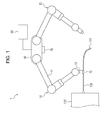
- a robot apparatus 1 is a robot that performs the work of assembling an apparatus 110.
- the configuration of attaching, by the robot apparatus 1, a second end of a cable (linear body) 100 whose first end is fixed to a main body of the apparatus 110 will be particularly described.
- the robot apparatus 1 includes a guide arm 10, a work arm 20, a camera 30, a body 40, and a controller 50.
- the guide arm 10 includes an arm main body 11, a gripper 12, and a force center 13.
- the arm main body 11 is an arm with a plurality of joints. A base end portion of the arm main body 11 is connected to the body 40.
- the gripper 12 is mounted to a tip portion of the arm main body 11. By causing the joints to swing, the arm main body 11 can move the gripper 12, attached to the tip portion of the arm main body 11, to an arbitrary position in the three-dimensional direction.
- the gripper 12 grips the cable 100.
- the force center 13 is provided at the tip portion of the arm main body 11, and detects a force applied to the gripper 12.
- the force center 13 detects, of a force applied to the gripper 12, a force in the opposite direction from the sliding direction of the gripper 12 moved by the arm main body 11.
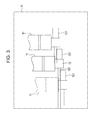
- the camera 30 is mounted to the body 40, and captures an image of the interior of a certain guide area R (see Fig. 3 ).
- the guide area R will be described in detail later.
- the camera 30 may be mounted to an appropriate position other than the body 40, such as near the tip portion of the arm main body 11.
- the work arm 20 grips a connector 101 mounted to the second end of the cable 100.
- the work arm 20 performs the work of attaching the second end of the cable 100, such as connecting the second end of the cable 100 to a certain position on the apparatus 110.
- the body 40 supports a base end portion of the guide arm 10 and a base end portion of the work arm 20 to be capable of swinging.
- the controller 50 controls the driving of the guide arm 10 and the work arm 20. Specifically, by using the guide arm 10 and the camera 30, the controller 50 detects the connector 101 mounted to the second end of the cable 100. By using the work arm 20, the controller 50 performs an attaching work, such as connecting the connector 101 to a certain position on the apparatus 110.
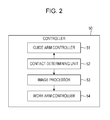
- the controller 50 includes a guide arm controller 51, a contact determining unit 52, an image processor 53, and a work arm controller 54.
- the controller 50 is physically configured of a computer system including a central processing unit (CPU), memory, and the like.
- the guide arm controller 51 controls the driving of the guide arm 10. Specifically, the guide arm controller 51 controls the arm main body 11 and the gripper 12 to grip a portion near the first end of the cable 100 (a portion near the end portion connected to the apparatus 110).
- the position of the cable 100 gripped by the gripper 12 is estimatable by detecting in advance the position at which the cable 100 is fixed to the apparatus 110.
- the position of the second end of the cable 100 differs from one cable 100 to another due to the habit of the cable 100 or the like and is thus difficult to be accurately estimated.
- the guide arm controller 51 controls the arm main body 11 and the gripper 12, slides the gripper 12 in a certain path toward the second end of the cable 100 while the gripper 12 is gripping the cable 100, and guides the second end of the cable 100 (connector 101) to the interior of the certain guide area R.
- the guide area R will be described.
- the length of the cable 100 is determined in advance by a specification, design, or the like.
- the gripper 12 which is gripping the cable 100, is slid in a certain path to the second end of the cable 100, the second end of the cable 100 is positioned in a certain area.
- the guide area R the area including the position of the second end of the cable 100 in the case where the gripper 12 is slid in a certain path.
- the length of the cable 100 may vary depending on tolerances or the like. If the length of the cable 100 varies from one to another, the position of the second end of the cable 100 in the case where the gripper 12 is slid in a certain path also varies.
- the guide area R is set in advance to include the positions of the second ends of these cables 100 with different lengths, if any.
- the guide arm controller 51 controls the arm main body 11 to decrease the sliding speed of the gripper 12 near the second end of the cable 100 where the connector 101 is provided.
- the guide arm controller 51 controls the arm main body 11 to decrease the sliding speed of the gripper 12 to be slower at the second end than the first end of the cable 100 by gradually decreasing the sliding speed as the gripper 12 approaches the second end of the cable 100, or by decreasing the speed of the gripper 12 to a certain speed when the gripper 12 becomes close to the second end of the cable 100 to a certain degree.
- the guide arm controller 51 When the guide arm controller 51 is notified by the contact determining unit 52 of the fact that the gripper 12 has been slid to the second end of the cable 100, the guide arm controller 51 stops sliding the gripper 12.
- the contact determining unit 52 determines whether the gripper 12 has been slid to the second end of the cable 100.
- the connector 101 is provided at the second end of the cable 100.
- the contact determining unit 52 determines that the gripper 12 has come into contact with the connector 101, that is, the gripper 12 has been slid to the second end of the cable 100.
- the contact determining unit 52 determines that the gripper 12 has been slid to the second end of the cable 100, the contact determining unit 52 notifies the guide arm controller 51 and the image processor 53 of the fact that the gripper 12 has been slid to the second end of the cable 100.
- the image processor 53 When the image processor 53 is notified by the contact determining unit 52 of the fact that the gripper 12 has been slid to the second end of the cable 100, the image processor 53 detects the posture of the connector 101 on the basis of an image including the guide area R, which is captured by the camera 30.
- Existing image processing technology can be used in this detection of the posture of the connector 101.
- the tilt of the connector 101, the rotation state of the connector 101, and the like are detectable.
- the work arm controller 54 controls the driving of the work arm 20. Specifically, the work arm controller 54 controls the work arm 20 to grip the connector 101 on the basis of the posture of the connector 101, detected by the image processor 53. The work arm controller 54 controls the work arm 20 to perform an attaching work, such as connecting the connector 101 to a certain position on the apparatus 110.
- the guide arm controller 51 first controls the guide arm 10 such that a portion near the first end of the cable 100 will be gripped by the gripper 12 (step S101).
- the guide arm controller 51 controls the arm main body 11 to slide the gripper 12 in a certain path toward the second end of the cable 100 while the gripper 12 is gripping the cable 100 (step S102). Accordingly, the second end of the cable 100 (connector 101) is guided to the interior of the guide area R.
- the contact determining unit 52 determines whether the gripper 12 has come into contact with the connector 101 (step S103).
- the guide arm controller 51 performs the above-described processing in step S102.
- the image processor 53 detects the posture of the connector 101 on the basis of an image captured by the camera 30 (step S104).
- the work arm controller 54 controls the work arm 20 to grip the connector 101, and performs the work of attaching the second end of the cable 100 (step S105).
- the embodiment is configured as described above.
- the robot apparatus 1 guides the connector 101 of the cable 100 to the interior of the guide area R by sliding the gripper 12 while the gripper 12 is gripping the cable 100.
- the robot apparatus 1 detects the posture of the connector 101 on the basis of an image captured by the camera 30.
- the robot apparatus 1 controls the work arm 20 to grip the connector 101, and performs the work of attaching the second end of the cable 100. In this manner, the connector 101 of the cable 100 can be guided to the interior of the guide area R by sliding the gripper 12, and the posture of the connector 101 becomes easily detectable on the basis of an image of the guide area R.
- the robot apparatus 1 can efficiently perform the work of attaching the cable 100.
- the guide arm controller 51 controls the arm main body 11 to decrease the sliding speed of the gripper 12 near the second end of the cable 100 where the connector 101 is provided. Accordingly, when the gripper 12 comes into contact with the connector 101, a force applied to the connector 101 becomes smaller, thereby suppressing the occurrence of failures such as dropping off of the connector 101 from the second end of the cable 100 or breakage of the connector 101.
- the robot apparatus 1 Since the robot apparatus 1 has the work arm 20, after the posture of the connector 101 has been detected, the robot apparatus 1 can grip the connector 101 with the work arm 20 and quickly perform the work of attaching the cable 100. While the cable 100 is being gripped by the gripper 12 of the guide arm 10, the work arm 20 can grip the connector 101. Thus, the positional displacement of the connector 101 does not occur, and the work arm 20 can easily grip the connector 101. Accordingly, because the robot apparatus 1 includes the guide arm 10 used to detect the position of the connector 101 and the work arm 20 which performs the work of attaching the cable 100, the robot apparatus 1 can more efficiently perform the work of attaching the cable 100.
- the fact that the gripper 12 has come into contact with the connector 101, provided at the second end of the cable 100, is detected. Accordingly, by detecting by the force center 13 the fact that the gripper 12 has come into contact with the connector 101, the fact that the gripper 12 has slid to the second end of the cable 100 is detectable.
- the embodiment has been described as above, the embodiment is not limited to the above-described example.
- the fact that the gripper 12 has come into contact with the connector 101, provided at the second end of the cable 100 is detected.
- an appropriate protrusion or the like may be provided at the second end of the cable 100, and the fact that the gripper 12 has been slid to the second end of the cable 100 may be detected.
- a protrusion or the like may be provided at the second end of the cable 100, and the fact that the gripper 12 has come into contact with this protrusion or the like may be detected.
- the gripper 12 may be slid at a constant speed, such as in the case where the gripper 12 is slid at a slow speed.
- the work of attaching the second end of the cable 100 is performed using the work arm 20, the work arm 20 may not necessarily be provided.
- the work of attaching the cable 100 may be performed by the guide arm 10.
- the guide arm 10 may be moved to align the position of the second end of the cable 100 at a certain position, or the cable 100 may be placed at a certain position, and then the gripper 12 of the guide arm 10 may re-grip the connector 101 and locate the second end of the cable 100 at a certain position.
- a sensor that detects whether the cable 100 is being gripped by the gripper 12 may be provided. In this case, if the gripper 12 fails in gripping the cable 100, for example, the gripper 12 may quickly re-grip the cable 100.
- the robot apparatus 1 may perform the work of attaching a linear body (such as a hose) other than the cable 100.
Landscapes
- Engineering & Computer Science (AREA)
- Robotics (AREA)
- Mechanical Engineering (AREA)
- Manipulator (AREA)
Applications Claiming Priority (1)
| Application Number | Priority Date | Filing Date | Title |
|---|---|---|---|
| JP2013051636A JP5672322B2 (ja) | 2013-03-14 | 2013-03-14 | ロボット装置 |
Publications (2)
| Publication Number | Publication Date |
|---|---|
| EP2783802A2 true EP2783802A2 (fr) | 2014-10-01 |
| EP2783802A3 EP2783802A3 (fr) | 2015-04-15 |
Family
ID=50189587
Family Applications (1)
| Application Number | Title | Priority Date | Filing Date |
|---|---|---|---|
| EP14157424.4A Ceased EP2783802A3 (fr) | 2013-03-14 | 2014-03-03 | Robot |
Country Status (4)
| Country | Link |
|---|---|
| US (1) | US9327405B2 (fr) |
| EP (1) | EP2783802A3 (fr) |
| JP (1) | JP5672322B2 (fr) |
| CN (1) | CN104044146A (fr) |
Cited By (9)
| Publication number | Priority date | Publication date | Assignee | Title |
|---|---|---|---|---|
| EP3702110A1 (fr) * | 2019-02-28 | 2020-09-02 | Seiko Epson Corporation | Système de robot et procédé de commande pour saisir un connecteur d'un câble |
| EP3772785A1 (fr) * | 2019-08-09 | 2021-02-10 | The Boeing Company | Procédé et système pour aligner et insérer un contact de câble avec des trous d'insertion de contact de câble d'un connecteur |
| EP3772786A1 (fr) * | 2019-08-09 | 2021-02-10 | The Boeing Company | Procédé et système pour aligner un contact de câble avec des trous d'insertion de contact de câble d'un connecteur |
| US11151405B1 (en) | 2020-06-19 | 2021-10-19 | The Boeing Company | Method and system for machine vision detection |
| US11577405B2 (en) | 2018-10-22 | 2023-02-14 | Fanuc Corporation | Robot hand and robot system |
| US11581690B2 (en) | 2017-05-09 | 2023-02-14 | Sony Corporation | Robot apparatus for producing electronic apparatus |
| US11670894B2 (en) | 2020-06-19 | 2023-06-06 | The Boeing Company | Method and system for error correction in automated wire contact insertion within a connector |
| US12132298B2 (en) | 2018-12-21 | 2024-10-29 | Rittal Gmbh & Co. Kg | Method for wiring electrical components of an electrical switchgear arranged on a mounting plate |
| US12191619B2 (en) | 2022-04-22 | 2025-01-07 | The Boeing Company | Method, system, and computer program product for wire connector assembly |
Families Citing this family (26)
| Publication number | Priority date | Publication date | Assignee | Title |
|---|---|---|---|---|
| JP6536110B2 (ja) * | 2015-03-20 | 2019-07-03 | セイコーエプソン株式会社 | ロボット制御装置、及び制御方法 |
| JP6816364B2 (ja) * | 2016-02-25 | 2021-01-20 | セイコーエプソン株式会社 | 制御装置、ロボット、及びロボットシステム |
| JP6753283B2 (ja) * | 2016-11-28 | 2020-09-09 | 富士通株式会社 | ケーブル敷設方法及びケーブル敷設装置 |
| CN108462020B (zh) * | 2017-02-20 | 2021-04-06 | 松下知识产权经营株式会社 | 作业装置 |
| WO2018193754A1 (fr) * | 2017-04-21 | 2018-10-25 | ソニー株式会社 | Appareil robotisé et procédé de production de dispositif électronique |
| JP7050218B2 (ja) * | 2017-07-20 | 2022-04-08 | パナソニックIpマネジメント株式会社 | 電子機器組立装置及び電子機器組立方法 |
| TWI808983B (zh) | 2017-09-08 | 2023-07-21 | 日商索尼股份有限公司 | 機器人手部、機器人裝置及電子機器的製造方法 |
| JP7294144B2 (ja) | 2018-01-19 | 2023-06-20 | ソニーグループ株式会社 | ロボット装置及び電子機器の製造方法 |
| CN108161928B (zh) * | 2018-02-13 | 2022-04-12 | 北京众驰自动化设备有限公司 | 机械臂夹抱物体的检测方法及装置 |
| EP3756835A4 (fr) | 2018-02-23 | 2021-12-15 | Kurashiki Boseki Kabushiki Kaisha | Procédé de déplacement de pointe d'objet linéaire, dispositif de commande et caméra tridimensionnelle |
| WO2019188196A1 (fr) * | 2018-03-28 | 2019-10-03 | 倉敷紡績株式会社 | Dispositif de commande de préhension |
| JP7225725B2 (ja) * | 2018-11-16 | 2023-02-21 | セイコーエプソン株式会社 | ロボットシステムおよび挿入方法 |
| JP7175203B2 (ja) * | 2019-01-15 | 2022-11-18 | 倉敷紡績株式会社 | 先端部材位置算出方法、先端部材把持方法、先端部材接続方法、先端部材位置算出システム、および、先端部材把持システム |
| JP2020121391A (ja) * | 2019-01-31 | 2020-08-13 | 川崎重工業株式会社 | ロボット及びその運転方法 |
| JP7358747B2 (ja) * | 2019-02-28 | 2023-10-11 | セイコーエプソン株式会社 | ロボットシステム |
| JP2020138293A (ja) * | 2019-02-28 | 2020-09-03 | セイコーエプソン株式会社 | ロボットシステムおよび制御方法 |
| JP7015265B2 (ja) * | 2019-03-14 | 2022-02-02 | ファナック株式会社 | コネクタを含むワークを把持する作業ツールおよび作業ツールを備えるロボット装置 |
| DE102019106710B4 (de) | 2019-03-15 | 2022-03-17 | Rittal Gmbh & Co. Kg | Greifer für die automatisierte Verdrahtung elektrischer Komponenten einer elektrischen Schaltanlage, ein entsprechender Roboter und ein entsprechendes Verfahren |
| US11258223B1 (en) | 2019-08-15 | 2022-02-22 | Design Ready Controls, Inc. | Automated flexible strand feeder assembly |
| JP7415606B2 (ja) * | 2020-01-30 | 2024-01-17 | セイコーエプソン株式会社 | 接続方法およびロボットシステム |
| DE102020105317A1 (de) | 2020-02-28 | 2021-09-02 | Rittal Gmbh & Co. Kg | Anordnung für die Bestückung und Verdrahtung elektronischer Komponenten im Schaltanlagenbau sowie ein entsprechendes Verfahren |
| JP7423153B2 (ja) * | 2020-03-26 | 2024-01-29 | 矢崎総業株式会社 | 布線機 |
| DE112021003858T5 (de) * | 2020-07-17 | 2023-05-25 | Fanuc Corporation | Roboterhand und Verfahren zum Greifen eines mit Steckern versehenen Kabelbaums |
| JP7552384B2 (ja) | 2021-01-28 | 2024-09-18 | セイコーエプソン株式会社 | ケーブル終端検出方法 |
| US12237636B2 (en) * | 2022-04-22 | 2025-02-25 | The Boeing Company | Method and system for machine determining wire contact insertion |
| CN121535788B (zh) * | 2026-01-19 | 2026-04-14 | 国网吉林省电力有限公司长春供电公司 | 一种基于视触融合的机器人夹取线缆系统及方法 |
Citations (2)
| Publication number | Priority date | Publication date | Assignee | Title |
|---|---|---|---|---|
| JP2003175481A (ja) * | 2001-12-11 | 2003-06-24 | Ricoh Co Ltd | ハンドリング装置 |
| JP4650411B2 (ja) | 2006-12-29 | 2011-03-16 | 三菱電機株式会社 | コネクタ自動挿抜装置及びコネクタ挿抜方法 |
Family Cites Families (28)
| Publication number | Priority date | Publication date | Assignee | Title |
|---|---|---|---|---|
| US3904234A (en) * | 1973-10-15 | 1975-09-09 | Stanford Research Inst | Manipulator with electromechanical transducer means |
| US4607430A (en) * | 1984-11-13 | 1986-08-26 | Westinghouse Electric Corp. | Method and apparatus for high density wire harness manufacture |
| GB8513648D0 (en) * | 1985-05-30 | 1985-07-03 | Beck M S | Slippage sensors |
| JPH0746288B2 (ja) * | 1987-10-19 | 1995-05-17 | 株式会社日立製作所 | 手先視覚を持つロボットの制御方法とその装置 |
| JPH01174209A (ja) * | 1987-12-28 | 1989-07-10 | Fujikura Ltd | 活線作業用マニピュレータの力覚検出方法 |
| US5157830A (en) * | 1988-07-01 | 1992-10-27 | Ttc Technology Trading Company | Method for automatically connecting electric conductors with contact parts to connector shells |
| US6325749B1 (en) * | 1996-10-18 | 2001-12-04 | Kabushiki Kaisha Yaskawa Denki | Robot vehicle for hot-line job |
| US6126651A (en) * | 1997-08-11 | 2000-10-03 | Mayer; Paul W. | Motorized motion-canceling suture tool holder |
| US6612143B1 (en) * | 2001-04-13 | 2003-09-02 | Orametrix, Inc. | Robot and method for bending orthodontic archwires and other medical devices |
| US7140655B2 (en) * | 2001-09-04 | 2006-11-28 | Multimetrixs Llc | Precision soft-touch gripping mechanism for flat objects |
| US6626238B2 (en) * | 2001-12-12 | 2003-09-30 | Offshore Energy Services, Inc. | Remote sensor for determining proper placement of elevator slips |
| US7182133B2 (en) * | 2002-02-04 | 2007-02-27 | Frank's Casing Crew And Rental Tools, Inc. | Elevator sensor |
| US7874352B2 (en) * | 2003-03-05 | 2011-01-25 | Weatherford/Lamb, Inc. | Apparatus for gripping a tubular on a drilling rig |
| JP3876234B2 (ja) * | 2003-06-17 | 2007-01-31 | ファナック株式会社 | コネクタ把持装置、同装置を備えたコネクタ検査システム及びコネクタ接続システム |
| DE602004019781D1 (de) * | 2003-06-20 | 2009-04-16 | Fanuc Robotics America Inc | Mehrfach-roboterarm-verfolgung und spiegel-jog |
| EP1515403B1 (fr) * | 2003-09-10 | 2007-10-24 | komax Holding AG | Dispositif de traitement de câble |
| JP2006102920A (ja) * | 2004-10-08 | 2006-04-20 | Fanuc Ltd | 把握型ハンド |
| US7285015B2 (en) * | 2005-03-19 | 2007-10-23 | Hirschmann Automotive Gmbh | Multiconductor flat ribbon cable plug connector |
| JP2006275979A (ja) * | 2005-03-30 | 2006-10-12 | National Institute Of Information & Communication Technology | センサ素子、センサ装置、対象物移動制御装置、対象物判別装置 |
| US7758573B2 (en) * | 2005-10-27 | 2010-07-20 | Terumo Kabushiki Kaisha | Blood vessel treatment method using multi-degree-of-freedom forceps |
| JP2007334678A (ja) * | 2006-06-15 | 2007-12-27 | Fanuc Ltd | ロボットシミュレーション装置 |
| JP5448326B2 (ja) * | 2007-10-29 | 2014-03-19 | キヤノン株式会社 | 把持装置および把持装置制御方法 |
| US7819183B2 (en) * | 2008-06-16 | 2010-10-26 | Halliburton Energy Services, Inc. | Work string controller |
| US8266940B2 (en) * | 2009-05-04 | 2012-09-18 | Orametrix, Inc. | Apparatus and method for customized shaping of orthodontic archwires and other medical devices |
| US9271718B2 (en) * | 2009-08-18 | 2016-03-01 | Karl Storz Gmbh & Co. Kg | Suturing and ligating method |
| US8861171B2 (en) * | 2010-02-10 | 2014-10-14 | Sri International | Electroadhesive handling and manipulation |
| JP5895337B2 (ja) * | 2010-09-15 | 2016-03-30 | セイコーエプソン株式会社 | ロボット |
| US9096317B2 (en) * | 2011-07-29 | 2015-08-04 | Telair International Gmbh | Cargo compartment with robot, aircraft, freight storage device |
-
2013
- 2013-03-14 JP JP2013051636A patent/JP5672322B2/ja not_active Expired - Fee Related
-
2014
- 2014-01-02 CN CN201410001433.9A patent/CN104044146A/zh active Pending
- 2014-02-19 US US14/183,526 patent/US9327405B2/en not_active Expired - Fee Related
- 2014-03-03 EP EP14157424.4A patent/EP2783802A3/fr not_active Ceased
Patent Citations (2)
| Publication number | Priority date | Publication date | Assignee | Title |
|---|---|---|---|---|
| JP2003175481A (ja) * | 2001-12-11 | 2003-06-24 | Ricoh Co Ltd | ハンドリング装置 |
| JP4650411B2 (ja) | 2006-12-29 | 2011-03-16 | 三菱電機株式会社 | コネクタ自動挿抜装置及びコネクタ挿抜方法 |
Cited By (11)
| Publication number | Priority date | Publication date | Assignee | Title |
|---|---|---|---|---|
| US11581690B2 (en) | 2017-05-09 | 2023-02-14 | Sony Corporation | Robot apparatus for producing electronic apparatus |
| US11577405B2 (en) | 2018-10-22 | 2023-02-14 | Fanuc Corporation | Robot hand and robot system |
| US12132298B2 (en) | 2018-12-21 | 2024-10-29 | Rittal Gmbh & Co. Kg | Method for wiring electrical components of an electrical switchgear arranged on a mounting plate |
| EP3702110A1 (fr) * | 2019-02-28 | 2020-09-02 | Seiko Epson Corporation | Système de robot et procédé de commande pour saisir un connecteur d'un câble |
| EP3772785A1 (fr) * | 2019-08-09 | 2021-02-10 | The Boeing Company | Procédé et système pour aligner et insérer un contact de câble avec des trous d'insertion de contact de câble d'un connecteur |
| EP3772786A1 (fr) * | 2019-08-09 | 2021-02-10 | The Boeing Company | Procédé et système pour aligner un contact de câble avec des trous d'insertion de contact de câble d'un connecteur |
| US11171459B2 (en) | 2019-08-09 | 2021-11-09 | The Boeing Company | Method and system for alignment of wire contact with wire contact insertion holes of a connector |
| US11374374B2 (en) | 2019-08-09 | 2022-06-28 | The Boeing Company | Method and system for alignment and insertion of wire contact with wire contact insertion holes of a connector |
| US11151405B1 (en) | 2020-06-19 | 2021-10-19 | The Boeing Company | Method and system for machine vision detection |
| US11670894B2 (en) | 2020-06-19 | 2023-06-06 | The Boeing Company | Method and system for error correction in automated wire contact insertion within a connector |
| US12191619B2 (en) | 2022-04-22 | 2025-01-07 | The Boeing Company | Method, system, and computer program product for wire connector assembly |
Also Published As
| Publication number | Publication date |
|---|---|
| JP2014176917A (ja) | 2014-09-25 |
| CN104044146A (zh) | 2014-09-17 |
| US9327405B2 (en) | 2016-05-03 |
| US20140277732A1 (en) | 2014-09-18 |
| JP5672322B2 (ja) | 2015-02-18 |
| EP2783802A3 (fr) | 2015-04-15 |
Similar Documents
| Publication | Publication Date | Title |
|---|---|---|
| EP2783802A2 (fr) | Robot | |
| CN110573311B (zh) | 机器人设备和电子设备制造方法 | |
| US11090814B2 (en) | Robot control method | |
| US10532461B2 (en) | Robot and robot system | |
| EP2489482A2 (fr) | Système de capture de travail | |
| CN106994680B (zh) | 机器人以及机器人系统 | |
| JP5682810B2 (ja) | ロボット | |
| US11518037B2 (en) | Robot system and control method | |
| CN111618844B (zh) | 机器人系统以及控制方法 | |
| CN110520255B (zh) | 机械手装置和电子设备的制造方法 | |
| CN111051016B (zh) | 机器人手、机器人设备和制造电子设备的方法 | |
| US20150343634A1 (en) | Robot, robot system, and control method | |
| US20160306340A1 (en) | Robot and control device | |
| US20150343642A1 (en) | Robot, robot system, and control method | |
| JP2020138293A5 (fr) | ||
| JP5574103B2 (ja) | 把持搬送装置 | |
| CN106233831A (zh) | 引线矫正装置、安装系统、基板制造方法 | |
| CN110914025B (zh) | 把持系统 | |
| JP6928316B2 (ja) | 押さえ機能を備える部品実装機 | |
| JP2015226967A (ja) | ロボット、ロボットシステム、制御装置、及び制御方法 | |
| CN110640772B (zh) | 抓取装置 | |
| CN115122321A (zh) | 机器人系统的控制方法、机器人系统及存储介质 | |
| JP2021020288A (ja) | 物体検出方法およびロボット |
Legal Events
| Date | Code | Title | Description |
|---|---|---|---|
| 17P | Request for examination filed |
Effective date: 20140303 |
|
| AK | Designated contracting states |
Kind code of ref document: A2 Designated state(s): AL AT BE BG CH CY CZ DE DK EE ES FI FR GB GR HR HU IE IS IT LI LT LU LV MC MK MT NL NO PL PT RO RS SE SI SK SM TR |
|
| AX | Request for extension of the european patent |
Extension state: BA ME |
|
| PUAI | Public reference made under article 153(3) epc to a published international application that has entered the european phase |
Free format text: ORIGINAL CODE: 0009012 |
|
| PUAL | Search report despatched |
Free format text: ORIGINAL CODE: 0009013 |
|
| AK | Designated contracting states |
Kind code of ref document: A3 Designated state(s): AL AT BE BG CH CY CZ DE DK EE ES FI FR GB GR HR HU IE IS IT LI LT LU LV MC MK MT NL NO PL PT RO RS SE SI SK SM TR |
|
| AX | Request for extension of the european patent |
Extension state: BA ME |
|
| RIC1 | Information provided on ipc code assigned before grant |
Ipc: B25J 9/16 20060101AFI20150306BHEP |
|
| R17P | Request for examination filed (corrected) |
Effective date: 20150824 |
|
| RBV | Designated contracting states (corrected) |
Designated state(s): AL AT BE BG CH CY CZ DE DK EE ES FI FR GB GR HR HU IE IS IT LI LT LU LV MC MK MT NL NO PL PT RO RS SE SI SK SM TR |
|
| 17Q | First examination report despatched |
Effective date: 20160707 |
|
| 18R | Application refused |
Effective date: 20170227 |