EP2784018A1 - Appareil de levage, générateur de turbine éolienne et procédé de maintenance pour générateur de turbine éolienne - Google Patents
Appareil de levage, générateur de turbine éolienne et procédé de maintenance pour générateur de turbine éolienne Download PDFInfo
- Publication number
- EP2784018A1 EP2784018A1 EP14154432.0A EP14154432A EP2784018A1 EP 2784018 A1 EP2784018 A1 EP 2784018A1 EP 14154432 A EP14154432 A EP 14154432A EP 2784018 A1 EP2784018 A1 EP 2784018A1
- Authority
- EP
- European Patent Office
- Prior art keywords
- nacelle
- rail
- wind turbine
- lifting apparatus
- turbine generator
- Prior art date
- Legal status (The legal status is an assumption and is not a legal conclusion. Google has not performed a legal analysis and makes no representation as to the accuracy of the status listed.)
- Granted
Links
- 238000012423 maintenance Methods 0.000 title claims description 29
- 238000000034 method Methods 0.000 title claims description 24
- 238000009434 installation Methods 0.000 claims description 3
- 238000005549 size reduction Methods 0.000 description 6
- 239000013585 weight reducing agent Substances 0.000 description 6
- 229910000831 Steel Inorganic materials 0.000 description 2
- 239000010959 steel Substances 0.000 description 2
- 230000000694 effects Effects 0.000 description 1
- 238000004519 manufacturing process Methods 0.000 description 1
- 239000000463 material Substances 0.000 description 1
- 230000002093 peripheral effect Effects 0.000 description 1
Images





Classifications
-
- B—PERFORMING OPERATIONS; TRANSPORTING
- B66—HOISTING; LIFTING; HAULING
- B66C—CRANES; LOAD-ENGAGING ELEMENTS OR DEVICES FOR CRANES, CAPSTANS, WINCHES, OR TACKLES
- B66C23/00—Cranes comprising essentially a beam, boom, or triangular structure acting as a cantilever and mounted for translatory of swinging movements in vertical or horizontal planes or a combination of such movements, e.g. jib-cranes, derricks, tower cranes
- B66C23/18—Cranes comprising essentially a beam, boom, or triangular structure acting as a cantilever and mounted for translatory of swinging movements in vertical or horizontal planes or a combination of such movements, e.g. jib-cranes, derricks, tower cranes specially adapted for use in particular purposes
- B66C23/20—Cranes comprising essentially a beam, boom, or triangular structure acting as a cantilever and mounted for translatory of swinging movements in vertical or horizontal planes or a combination of such movements, e.g. jib-cranes, derricks, tower cranes specially adapted for use in particular purposes with supporting couples provided by walls of buildings or like structures
- B66C23/207—Cranes comprising essentially a beam, boom, or triangular structure acting as a cantilever and mounted for translatory of swinging movements in vertical or horizontal planes or a combination of such movements, e.g. jib-cranes, derricks, tower cranes specially adapted for use in particular purposes with supporting couples provided by walls of buildings or like structures with supporting couples provided by wind turbines
-
- F—MECHANICAL ENGINEERING; LIGHTING; HEATING; WEAPONS; BLASTING
- F05—INDEXING SCHEMES RELATING TO ENGINES OR PUMPS IN VARIOUS SUBCLASSES OF CLASSES F01-F04
- F05B—INDEXING SCHEME RELATING TO WIND, SPRING, WEIGHT, INERTIA OR LIKE MOTORS, TO MACHINES OR ENGINES FOR LIQUIDS COVERED BY SUBCLASSES F03B, F03D AND F03G
- F05B2230/00—Manufacture
- F05B2230/60—Assembly methods
- F05B2230/61—Assembly methods using auxiliary equipment for lifting or holding
-
- Y—GENERAL TAGGING OF NEW TECHNOLOGICAL DEVELOPMENTS; GENERAL TAGGING OF CROSS-SECTIONAL TECHNOLOGIES SPANNING OVER SEVERAL SECTIONS OF THE IPC; TECHNICAL SUBJECTS COVERED BY FORMER USPC CROSS-REFERENCE ART COLLECTIONS [XRACs] AND DIGESTS
- Y02—TECHNOLOGIES OR APPLICATIONS FOR MITIGATION OR ADAPTATION AGAINST CLIMATE CHANGE
- Y02E—REDUCTION OF GREENHOUSE GAS [GHG] EMISSIONS, RELATED TO ENERGY GENERATION, TRANSMISSION OR DISTRIBUTION
- Y02E10/00—Energy generation through renewable energy sources
- Y02E10/70—Wind energy
- Y02E10/72—Wind turbines with rotation axis in wind direction
Definitions
- the present disclosure relates to a lifting apparatus, a wind turbine generator equipped with this lifting apparatus, and a maintenance method for the wind turbine generator.
- a wind turbine generator includes a rotor having a hub and blades attached to the hub.
- the rotor is installed to a nacelle mounted on a tower which is installed onshore or offshore.
- rotor rotates when the blades receive wind, the rotation of the rotor is transmitted via a drive train to a generator housed in the nacelle, and then electric power is generated by the generator.
- the nacelle mounted on the tower 1 accommodates a variety of components. When assembling or performing maintenance of the wind turbine generator, those components need to be transferred.
- Transferring objects such as a maintenance object part exist in many places inside the nacelle.
- a lifting apparatus such as a crane is used to transfer the transferring object between the nacelle and the tower, or between a nacelle interior space and a nacelle exterior space.
- a lifting apparatus used for a wind turbine generator there is a nacelle mounted maintenance system described in Patent Reference 1.
- This maintenance system uses a jib crane.
- the jib crane is configured by a support column and a jib which is attached to the support column and is pivotable around the support column.
- the jib crane has a cantilever structure. Components are lifted and lowered by a hoisting apparatus attached to an end of the jib, such as a hoist and a winch.
- Patent Reference 2 describes a crane installed in a nacelle of a wind turbine generator.
- the crane is configured such that an aft end of a crane beam is secured to an aft part of the nacelle, and the crane beam is rotatable around the fixed part as a pivot point along an arc shaped rail fixed to a main bearing.
- the jib crane described in Patent Reference 1 has a cantilever structure.
- a hoisted load is at a position distant from the support column and thus the moment is applied to the support column. Therefore, it is necessary to attain rigidity of the post. This, however, requires increase in size of the support column, e.g. the size, resulting in weight increase.
- Patent Reference 2 has a both end supported structure.
- the required rigidity is small compared to the jib crane and the like.
- the shape of the fixed rail is limited to a circular arc shape and thus, a movable range (a fan-shaped range) of the crane beam along the circular arc-shaped fixed rail is also limited.
- the beam is configured to slide relative to the support column.
- the beam is rotatable while the distal end of the beam is engaged with the rail. Therefore, rails of any shape can be used.
- the shape of the rail is not limited to a circular arc having single radius of curvature, but may include a combination of arcs having different radiuses, a combination of a straight line part and a curved part, and so on.
- the beam is supported by the rail and the support column, and thus, compared to the cantilever structure, the required rigidity for the beam and the support column is reduced, and it is possible to achieve weight reduction and size reduction of the lifting apparatus.
- the rail may be at least in part constituted by an upper frame of the nacelle which is disposed along an edge of a ceiling of the nacelle.
- the upper frame of the nacelle By using the upper frame of the nacelle to constitute at least a part of the rail, it is possible to install the lifting apparatus in a limited space inside the nacelle. As a result, it is possible to reduce weight of the nacelle.
- the upper frame has at least one corner
- the rail includes a part of the upper frame except the at least one corner, and a curved frame which is disposed on each of the at least one corner and connected to said part of the upper frame.
- the corner of the upper frame can be replaced by a curved frame and the rest of the upper frame except the corner can be used as the rail. As a result, the beam can smoothly slide along the rail.
- the beam is supported by a nacelle frame which constitutes at least a part of the rail and which bears a structural strength of the nacelle.
- the beam can be reliably supported.
- the lifting apparatus for the wind turbine generator further comprises:
- the lifting apparatus for the wind turbine generator may further comprise:
- the rotation of the first member relative to the support column is facilitated by the operation of the first bearing facilitates.
- the beam can smoothly pivot around the support column.
- sliding resistance between the first member and the beam is reduced by the operation of the first roller.
- the beam can slide smoothly relative to the first member in the longitudinal direction of the beam.
- sliding resistance between the guide part and the beam is reduced by using the first guide part including at least two first side rollers disposed on both sides of the beam in the width direction.
- the beam can slide more smoothly in the longitudinal direction.
- the lifting apparatus for the wind turbine generator may further comprise:
- the angle of the beam relative to the rail is variable during rotation of the beam around the support column, by rotating the second member which is engaged with the rail. As a result, the beam can rotate smoothly around the support column.
- the second member is configured to be slidable along the rail by means of the second guide part provided for the second member. As a result, the distal end of the beam can move smoothly along the rail.
- the lifting apparatus for the wind turbine generator may further comprise:
- the rotation of the second member relative to the distal end of the beam is facilitated by the operation of the second bearing facilitates.
- the angle between the beam and the rail can be varied smoothly during rotation of the beam around the support column.
- sliding resistance between the second member and the rail is reduced by the operation of the second roller.
- the second member can slide smoothly along the rail.
- sliding resistance between the second guide part and the rail is reduced by using the second guide part including at least two second side rollers disposed on both sides of the beam in the width direction.
- the distal end of the beam can move more smoothly along the rail.
- the lifting unit includes one of a winch, a hoist or a crane.
- the beam is configured to be slidable relative to the support column in a longitudinal direction of the beam.
- the beam is rotatable while the distal end of the beam is engaged with the rail. Therefore, rails of any shape can be used.
- the shape of the rail is not limited to a circular arc having single radius of curvature, but may include a combination of arcs having different radiuses, a combination of a straight line part and a curved part, and so on.
- the beam is supported by both the rail and the support column, and thus, compared to the cantilever structure, the required rigidity for the beam and the support column is reduced, and it is possible to achieve weight reduction and size reduction of the lifting apparatus.
- the wind turbine generator further comprises:
- the bearing housing of the main bearing is normally fixed to a member of high rigidity which is called a nacelle bedplate. Therefore, the bearing housing of the main bearing (the rear bearing) is utilized to support the support column of the lifting apparatus, so as to reliably support the lifting apparatus.
- an over-hang amount from the front bearing affects a moment load on a shaft system significantly.
- the front bearing is often disposed closer to a nacelle front.
- the rear bearing is disposed closer to the center of the nacelle than the front bearing, and the nacelle interior space normally expands to the rear past the rear bearing so as to accommodate a variety of devices and equipments.
- the beam is configured to be slidable relative to the support column in a longitudinal direction of the beam.
- the beam is rotatable while the distal end of the beam is engaged with the rail. Therefore, rails of any shape can be used.
- the shape of the rail is not limited to a circular arc having single radius of curvature, but may include a combination of arcs having different radiuses, a combination of a straight line part and a curved part, and so on.
- the beam is supported by both the rail and the support column, and thus, compared to the cantilever structure, the required rigidity for the beam and the support column is reduced, and it is possible to achieve weight reduction and size reduction of the lifting apparatus.
- the wind turbine generator comprises a tower which is configured to support the nacelle via a yaw bearing and, in the object transferring step, the object is transferred by the lifting apparatus between the nacelle and the tower through an inside of the yaw bearing.
- the object in the object transferring step, is transferred by the lifting apparatus between an interior space and an exterior space of the nacelle through an opening provided in a floor of the nacelle.
- the beam is configured to be slidable relative to the support column.
- the shape of the rail is not limited to a circular arc having single radius of curvature and may be any shape.
- the beam is supported by both the rail and the support column, and thus, compared to the cantilever structure, the required rigidity for the beam and the support column is reduced, and it is possible to achieve weight reduction and size reduction of the lifting apparatus.
- a variety of devices including the main shaft 6 are accommodated in a nacelle 30 mounted on a tower 8 which is installed in a standing manner offshore or on the ground, and may be covered by a nacelle cover 30B of the nacelle 30. Further, the hub 4 may be covered by a hub cover (spinner) 5.
- a drive train 10 may be configured by a hydraulic drive train including a hydraulic pump, a high pressure oil line, a low pressure oil line and a hydraulic motor, or a mechanical speed increaser (gear type).
- the wind turbine generator may be a direct-drive wind turbine generator which is configured such that the hub 4 and the generator 16 are directly connected without the drive train.
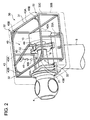
- FIG.2 is an oblique perspective view of an exemplary configuration inside a nacelle of a lifting apparatus in relation to an embodiment.
- a lifting apparatus 40 installed in the nacelle 30 comprises a lifting unit 41, a beam 42 configured to support the lifting unit 41, a rail 43 placed in the nacelle 30, and a support column 44 installed in a standing manner in the nacelle 30.
- the rail 43 is configured to engage with a distal end of the beam 42.
- the shape of the rail 43 is not particularly limited.
- the shape of the rail 43 may be a circular arc having single radius of curvature, a combination of arcs having different radiuses, a combination of a straight line part and a curved part, etc.
- the rail 43 has an approximately rectangular shape formed by a combination of a straight line part (a part of an upper frame 31 except corners, which is described later) and a curved part (a curved frame 43B which is described later).
- the support column 44 is configured to rotatably support the beam 42 so that the distal end of the beam 42 moves along the rail 43.
- the beam 42 is attached to the support column 44 to be slidable relative to the support column 44 in a longitudinal direction of the beam 42.
- the upper frame 31 may have at least one corner 32
- the rail 43 may include a part 43A of the upper frame 31 except the at least one corner 32, and a curved frame 43B which is disposed on each of the at least one corner 32 and connected to the part 43A of the upper frame 31.
- the upper frame 31 of a rectangular shape has four corners 32
- the rail 43 includes four straight line parts 43A of the upper frame 31 except the corners 32
- the curved frames 43B which are respectively disposed on the corners 32 and connected to the four straight line part 43A of the upper frame 31 so that the rail 43 overall has an approximately rectangular shape.
- the beam 42 may be supported by a nacelle frame 30C which constitutes at least a part of the rail 43.
- the nacelle frame 30C is a structure which is arranged to surround objects accommodated in the nacelle 30 and which is configured to bear a structural strength of the nacelle 30.
- the above-mentioned upper frame 31 is a section of the nacelle frame 30C which is disposed along an edge of a ceiling of the nacelle 30.
- the support column 44 of the lifting apparatus 40 may be supported by a bearing housing 22 of a rear bearing 20B of the pair of main bearings 20, which is disposed farther from the hub 4.
- the support column 44 may be supported by the bearing housing 22 via a support column receiving part 45 (see FIG.2 ), instead of being directly connected to the bearing housing 22.
- a support column receiving part 45 see FIG.2
- the position of the support column 44 in the nacelle 30 can be adjusted by adjusting an extension amount of the support column receiving part 45 that extends from the bearing housing 22.
- the movable range of the lifting unit 41 can cover a large area around the center of the nacelle 30.
- FIG. 3 is a perspective view of a configuration of the lifting apparatus in relation to an embodiment.
- FIG. 4 is a plan view of the lifting apparatus in relation to an embodiment, taken in A direction of FIG.3 .
- the lifting unit 41 is not shown.
- FIG. 5 is a side view of an engagement part (a first engagement part) between the beam and the support column, taken in B direction of FIG.4 .
- FIG. 6 is a cross-sectional view of an engagement part (a second engagement part) between the distal end of the beam and the rail, taken along C-C line of FIG.4 .
- the lifting apparatus 40 may further comprise a first member 51 and a first guide part 54 in the engagement part (the first engagement part) 46 between the beam 42 and the support column 44.
- the first guide part 54 is provided for the first member 51 to guide the beam 42 so that the beam 42 is slidable relative to the first member 51 in the longitudinal direction of the beam 42.
- the support column 33 includes a body portion 44A, a distal end portion 44B which is attached to the body portion 44A by flange fastening, and the first member 51 is attached to the distal end portion 44B of the support column 44 via the first bearing 53 which is described later.
- the first member 51 is rotatably supported by the first bearing 53 to be rotatable relative to the support column 44 around a rotation axis P.
- a first roller 52 may be provided for the first member 51 as illustrated in FIG.4 and FIG.5 .
- the first roller 52 is configured to contact the beam 42 while rotating about a rotation axis O extending along the width direction of the beam 42.
- the first roller 52 contacts a bottom surface 42L of the beam 42, and there is a clearance F (see FIG.5 ) between a top surface 51U of the first member 51 and the bottom surface 42L of the beam 42 so that the top surface 51U of the first member 51 does not contact the bottom surface 42L of the beam 42.
- a clearance F see FIG.5
- the beam 42 can slide smoothly relative to the support column 44.
- the beam 43 is formed by H-section steel and is configured such that the first roller 52 contacts the bottom surface 42L of a lower flange of the H-section.
- the first guide part 54 may comprise at least two first side rollers 55 disposed on both sides of the beam 42 in the width direction of the beam 42 to contact side faces of the beam 42.
- the at least two first side rollers 55 are configured to contact the side faces of the lower flange 42F of the beam 42.
- a pair of the first side rollers 55 is disposed to sandwich the lower flange 42F, and such pair of the first side rollers 55 is provided on either side of the rotation axis P in the longitudinal direction of the beam 42.
- the second member 61 is rotatably attached to the distal end 42A of the beam 42 and configured to engage with the rail 43.
- the second guide part 64 is provided for the second member 61 to guide the second member 61 so that the second member 61 is slidable along the rail 43.
- the rail 43 is formed by an H-section steel having a lower flange and an upper flange.
- FIG.6 illustrates the peripheral structure of the upper flange 43F of the rail. The lower flange of the rail 43 is not shown in the drawing.
- a second bearing 63 may be provided between the second member 61 and the distal end of the beam 42 to rotatably support the second member 61 to the beam 42 so that the second member 61 is rotatable around the rotation axis R which is perpendicular to a top surface 43U of the rail 43.
- a second roller 62 may be provided for the second member 61.
- the second roller 62 is configured to contact the rail 43 while rotating about a rotation axis Q extending along the width direction of the rail 43.
- a power source such as a motor 66 may be attached to the second member 61.
- the motor 66 is configured to transmit power to the second roller 62 via a rotation shaft 67.
- the rotation shaft 67 of the second roller 62 may be attached to the second member 61 via a bearing 68.
- the at least two second side rollers 61 are configured to contact the side faces 43S of the upper flange 43A of the rail 43.
- a pair of the second side rollers 62 is disposed to sandwich the upper flange 43A, and such pair of the second side rollers 62 is provided on either side of the rotation axis R in the longitudinal direction of the rail 43.
- the lifting unit 41 may be any equipment capable of lifting a cargo and may include one of a winch, a hoist or a crane.
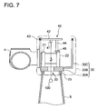
- FIG.7 is an illustration of conveyance of an object according to the maintenance method for the wind turbine generator in relation to an embodiment.
- the maintenance method for the wind turbine generator comprises an object transferring step of transferring an object 100 using the lifting apparatus 40 installed in the nacelle 30, as illustrated in FIG.7 .
- the object 100 is transferred by the above described lifting apparatus 40 installed in the nacelle 30, between the nacelle 30 and the tower 8 through an inside of the yaw bearing 23.
- An opening 33 is provided in the nacelle bedplate 30A so that the object 100 can pass through.
- FIG.8 is an illustration of conveyance of the object according to the maintenance method for the wind turbine generator in relation to another embodiment.
- the object 100 may be transferred by the lifting apparatus 40 installed in the nacelle 30, between an interior space 70 and an exterior space 80 of the nacelle 30 through an opening 34 provided in a floor of the nacelle 30.
- FIG.9A, FIG.9B and FIG.9C illustrate the process of transferring a heavy object by a temporary lifting apparatus according to the maintenance method for the wind turbine in relation to an embodiment.
- the object 100 to be transferred is a component 91 of a temporary lifting apparatus 90 which has a lifting capacity larger than the lifting apparatus 40.
- the component 91 of the temporary lifting apparatus 90 is transferred into the nacelle 30 by the lifting apparatus 40.
- FIG.9A illustrates transferring of the component 91 from the tower 8 into the nacelle 30 through the inside of the yaw bearing 23. This is, however, not restrictive and the component 91 may be transferred from the exterior space 80 into the interior space 70 of the nacelle 30 through the opening 34 provided in the floor of the nacelle 30.
- the components 91 are assembled into the temporary lifting apparatus 90, and the temporary lifting apparatus 90 is installed in the nacelle 30 as illustrated in the drawing.
- a heavy object 101 which is heavier than the object 100 is transferred by the temporary lifting apparatus 90, between the interior space 70 and the exterior space 80 of the nacelle 30 through the opening 34 provided in the floor of the nacelle 30.
Landscapes
- Engineering & Computer Science (AREA)
- Civil Engineering (AREA)
- Structural Engineering (AREA)
- Mechanical Engineering (AREA)
- Wind Motors (AREA)
Applications Claiming Priority (1)
| Application Number | Priority Date | Filing Date | Title |
|---|---|---|---|
| JP2013069201A JP2014190313A (ja) | 2013-03-28 | 2013-03-28 | 吊り上げ装置、風力発電装置および風力発電装置のメンテナンス方法 |
Publications (2)
| Publication Number | Publication Date |
|---|---|
| EP2784018A1 true EP2784018A1 (fr) | 2014-10-01 |
| EP2784018B1 EP2784018B1 (fr) | 2017-06-14 |
Family
ID=50071468
Family Applications (1)
| Application Number | Title | Priority Date | Filing Date |
|---|---|---|---|
| EP14154432.0A Not-in-force EP2784018B1 (fr) | 2013-03-28 | 2014-02-10 | Appareil de levage, générateur de turbine éolienne et procédé de maintenance pour générateur de turbine éolienne |
Country Status (2)
| Country | Link |
|---|---|
| EP (1) | EP2784018B1 (fr) |
| JP (1) | JP2014190313A (fr) |
Cited By (6)
| Publication number | Priority date | Publication date | Assignee | Title |
|---|---|---|---|---|
| EP2865891A1 (fr) * | 2013-10-17 | 2015-04-29 | Mitsubishi Heavy Industries, Ltd. | Dispositif de levage d'équipement pour une éolienne et procédé d'installation du dit dispositif |
| CN107939611A (zh) * | 2017-11-14 | 2018-04-20 | 德阳东汽电站机械制造有限公司 | 一种大型风力发电机后机架及其生产装配方法 |
| US10094357B2 (en) * | 2013-11-27 | 2018-10-09 | Vestas Wind Systems A/S | Nacelle for a wind turbine generator including lifting apparatus |
| CN113294294A (zh) * | 2021-07-08 | 2021-08-24 | 哈电风能有限公司 | 发电机组 |
| CN113315318A (zh) * | 2021-05-11 | 2021-08-27 | 中国长江电力股份有限公司 | 一种适用于大型水轮发电机定转子的检查装置及检查方法 |
| EP4198301B1 (fr) | 2014-10-07 | 2025-01-29 | Liftra IP ApS | Fixation d'arbre principal |
Families Citing this family (3)
| Publication number | Priority date | Publication date | Assignee | Title |
|---|---|---|---|---|
| KR101614497B1 (ko) | 2015-06-11 | 2016-04-25 | 김병연 | 풍력발전기의 로터 조립용 허브 받침대 |
| EP4048887A1 (fr) * | 2019-10-22 | 2022-08-31 | LiftWerx Holdings Inc. | Système de levage pour une pale de rotor d'une éolienne |
| DK181017B1 (en) * | 2021-05-03 | 2022-09-26 | Liftra Ip Aps | Base for supporting a portable crane |
Citations (3)
| Publication number | Priority date | Publication date | Assignee | Title |
|---|---|---|---|---|
| WO2005031159A1 (fr) * | 2003-09-26 | 2005-04-07 | Neg Micon A/S | Procede d'entretien d'eolienne mettant en oeuvre un equipement monte sur le moyeu |
| WO2007107817A1 (fr) * | 2006-03-23 | 2007-09-27 | Clipper Windpower Technology, Inc. | Nacelle d'eolienne avec grue d'entretien incorporee pour l'acces aux composants de l'eolienne |
| WO2009155934A1 (fr) * | 2008-06-27 | 2009-12-30 | Vestas Wind Systems Us | Pont roulant pour nacelle |
-
2013
- 2013-03-28 JP JP2013069201A patent/JP2014190313A/ja active Pending
-
2014
- 2014-02-10 EP EP14154432.0A patent/EP2784018B1/fr not_active Not-in-force
Patent Citations (3)
| Publication number | Priority date | Publication date | Assignee | Title |
|---|---|---|---|---|
| WO2005031159A1 (fr) * | 2003-09-26 | 2005-04-07 | Neg Micon A/S | Procede d'entretien d'eolienne mettant en oeuvre un equipement monte sur le moyeu |
| WO2007107817A1 (fr) * | 2006-03-23 | 2007-09-27 | Clipper Windpower Technology, Inc. | Nacelle d'eolienne avec grue d'entretien incorporee pour l'acces aux composants de l'eolienne |
| WO2009155934A1 (fr) * | 2008-06-27 | 2009-12-30 | Vestas Wind Systems Us | Pont roulant pour nacelle |
Cited By (7)
| Publication number | Priority date | Publication date | Assignee | Title |
|---|---|---|---|---|
| EP2865891A1 (fr) * | 2013-10-17 | 2015-04-29 | Mitsubishi Heavy Industries, Ltd. | Dispositif de levage d'équipement pour une éolienne et procédé d'installation du dit dispositif |
| US10094357B2 (en) * | 2013-11-27 | 2018-10-09 | Vestas Wind Systems A/S | Nacelle for a wind turbine generator including lifting apparatus |
| EP4198301B1 (fr) | 2014-10-07 | 2025-01-29 | Liftra IP ApS | Fixation d'arbre principal |
| CN107939611A (zh) * | 2017-11-14 | 2018-04-20 | 德阳东汽电站机械制造有限公司 | 一种大型风力发电机后机架及其生产装配方法 |
| CN107939611B (zh) * | 2017-11-14 | 2019-06-25 | 德阳东汽电站机械制造有限公司 | 一种大型风力发电机后机架及其生产装配方法 |
| CN113315318A (zh) * | 2021-05-11 | 2021-08-27 | 中国长江电力股份有限公司 | 一种适用于大型水轮发电机定转子的检查装置及检查方法 |
| CN113294294A (zh) * | 2021-07-08 | 2021-08-24 | 哈电风能有限公司 | 发电机组 |
Also Published As
| Publication number | Publication date |
|---|---|
| EP2784018B1 (fr) | 2017-06-14 |
| JP2014190313A (ja) | 2014-10-06 |
Similar Documents
| Publication | Publication Date | Title |
|---|---|---|
| EP2784018B1 (fr) | Appareil de levage, générateur de turbine éolienne et procédé de maintenance pour générateur de turbine éolienne | |
| EP1859165B1 (fr) | Nacelle d'eolienne avec grue d'entretien incorporee pour l'acces aux composants de l'eolienne | |
| EP2672106B1 (fr) | Système et procédé permettant d'assembler et de désassembler des composants d'une turbine éolienne | |
| EP2520533B2 (fr) | Grue de service pour éolienne | |
| EP2868914B1 (fr) | Dispositif et procédé permettant d'attacher et de détacher une pale pour éolienne | |
| EP2585712B1 (fr) | Dispositif de levage et procédé pour le positionnement d'un objet encombrant | |
| EP2484891B1 (fr) | Générateur d'éolienne doté d'un dispositif de levage | |
| EP2505823B1 (fr) | Trame de transport pour unité de moyeu de rotor/nacelle d'une éolienne, procédé de transport et de montage d'une unité de moyeu de rotor/nacelle | |
| EP2652317B1 (fr) | Transport de composants de transmission dans une nacelle de turbine éolienne | |
| EP2924284B1 (fr) | Contrebalancer un moyeu d'éolienne | |
| US20130106109A1 (en) | Wind power installation and method for adjusting the rotor rotation axis | |
| EP2563707B1 (fr) | Grue pour manipuler les composants d'une génératrice éolienne et procédé de levage d'une telle grue | |
| EP3828121A1 (fr) | Grue et procédé de montage d'une tour | |
| US20100143136A1 (en) | Systems and methods for assembling a pitch assembly for use in a wind turbine | |
| EP3676492B1 (fr) | Éolienne dotée d'un contenant mobile logeant un mécanisme de levage | |
| DK2538073T3 (en) | An improvement of a horizontal wing installation of windmills | |
| BE1021795B1 (nl) | Inrichting en werkwijze voor het assembleren van een bouwwerk op zee | |
| EP3642476B1 (fr) | Éolienne à rotors multiples dotée de fils de retenue | |
| EP3844389B1 (fr) | Ensemble contrepoids destiné à être utilisé pendant l'installation d'une pale unique d'éolienne | |
| EP2865891B1 (fr) | Dispositif de levage d'équipement pour une éolienne et un procédé d'installation de l'éolienne | |
| GB2577643A (en) | Method for assembling a wind turbine and a wind turbine system | |
| EP4144986B1 (fr) | Nacelles de turbine éolienne avec au moins un panneau de toit déplaçable | |
| EP3782950A1 (fr) | Nacelle pour éolienne | |
| KR20100090499A (ko) | 터어빈 부품 억세스용 일체형 서비스 크레인을 구비한 풍력터어빈 너셀 |
Legal Events
| Date | Code | Title | Description |
|---|---|---|---|
| 17P | Request for examination filed |
Effective date: 20140210 |
|
| AK | Designated contracting states |
Kind code of ref document: A1 Designated state(s): AL AT BE BG CH CY CZ DE DK EE ES FI FR GB GR HR HU IE IS IT LI LT LU LV MC MK MT NL NO PL PT RO RS SE SI SK SM TR |
|
| AX | Request for extension of the european patent |
Extension state: BA ME |
|
| PUAI | Public reference made under article 153(3) epc to a published international application that has entered the european phase |
Free format text: ORIGINAL CODE: 0009012 |
|
| R17P | Request for examination filed (corrected) |
Effective date: 20150319 |
|
| RBV | Designated contracting states (corrected) |
Designated state(s): AL AT BE BG CH CY CZ DE DK EE ES FI FR GB GR HR HU IE IS IT LI LT LU LV MC MK MT NL NO PL PT RO RS SE SI SK SM TR |
|
| GRAP | Despatch of communication of intention to grant a patent |
Free format text: ORIGINAL CODE: EPIDOSNIGR1 |
|
| RIC1 | Information provided on ipc code assigned before grant |
Ipc: B66C 23/20 20060101AFI20161208BHEP |
|
| INTG | Intention to grant announced |
Effective date: 20170110 |
|
| GRAS | Grant fee paid |
Free format text: ORIGINAL CODE: EPIDOSNIGR3 |
|
| GRAA | (expected) grant |
Free format text: ORIGINAL CODE: 0009210 |
|
| AK | Designated contracting states |
Kind code of ref document: B1 Designated state(s): AL AT BE BG CH CY CZ DE DK EE ES FI FR GB GR HR HU IE IS IT LI LT LU LV MC MK MT NL NO PL PT RO RS SE SI SK SM TR |
|
| REG | Reference to a national code |
Ref country code: GB Ref legal event code: FG4D |
|
| REG | Reference to a national code |
Ref country code: CH Ref legal event code: EP Ref country code: AT Ref legal event code: REF Ref document number: 900767 Country of ref document: AT Kind code of ref document: T Effective date: 20170615 |
|
| REG | Reference to a national code |
Ref country code: IE Ref legal event code: FG4D |
|
| REG | Reference to a national code |
Ref country code: DE Ref legal event code: R096 Ref document number: 602014010643 Country of ref document: DE |
|
| REG | Reference to a national code |
Ref country code: NL Ref legal event code: MP Effective date: 20170614 |
|
| REG | Reference to a national code |
Ref country code: LT Ref legal event code: MG4D |
|
| PG25 | Lapsed in a contracting state [announced via postgrant information from national office to epo] |
Ref country code: FI Free format text: LAPSE BECAUSE OF FAILURE TO SUBMIT A TRANSLATION OF THE DESCRIPTION OR TO PAY THE FEE WITHIN THE PRESCRIBED TIME-LIMIT Effective date: 20170614 Ref country code: NO Free format text: LAPSE BECAUSE OF FAILURE TO SUBMIT A TRANSLATION OF THE DESCRIPTION OR TO PAY THE FEE WITHIN THE PRESCRIBED TIME-LIMIT Effective date: 20170914 Ref country code: LT Free format text: LAPSE BECAUSE OF FAILURE TO SUBMIT A TRANSLATION OF THE DESCRIPTION OR TO PAY THE FEE WITHIN THE PRESCRIBED TIME-LIMIT Effective date: 20170614 Ref country code: HR Free format text: LAPSE BECAUSE OF FAILURE TO SUBMIT A TRANSLATION OF THE DESCRIPTION OR TO PAY THE FEE WITHIN THE PRESCRIBED TIME-LIMIT Effective date: 20170614 Ref country code: GR Free format text: LAPSE BECAUSE OF FAILURE TO SUBMIT A TRANSLATION OF THE DESCRIPTION OR TO PAY THE FEE WITHIN THE PRESCRIBED TIME-LIMIT Effective date: 20170915 |
|
| REG | Reference to a national code |
Ref country code: AT Ref legal event code: MK05 Ref document number: 900767 Country of ref document: AT Kind code of ref document: T Effective date: 20170614 |
|
| PG25 | Lapsed in a contracting state [announced via postgrant information from national office to epo] |
Ref country code: BG Free format text: LAPSE BECAUSE OF FAILURE TO SUBMIT A TRANSLATION OF THE DESCRIPTION OR TO PAY THE FEE WITHIN THE PRESCRIBED TIME-LIMIT Effective date: 20170914 Ref country code: RS Free format text: LAPSE BECAUSE OF FAILURE TO SUBMIT A TRANSLATION OF THE DESCRIPTION OR TO PAY THE FEE WITHIN THE PRESCRIBED TIME-LIMIT Effective date: 20170614 Ref country code: SE Free format text: LAPSE BECAUSE OF FAILURE TO SUBMIT A TRANSLATION OF THE DESCRIPTION OR TO PAY THE FEE WITHIN THE PRESCRIBED TIME-LIMIT Effective date: 20170614 Ref country code: LV Free format text: LAPSE BECAUSE OF FAILURE TO SUBMIT A TRANSLATION OF THE DESCRIPTION OR TO PAY THE FEE WITHIN THE PRESCRIBED TIME-LIMIT Effective date: 20170614 Ref country code: NL Free format text: LAPSE BECAUSE OF FAILURE TO SUBMIT A TRANSLATION OF THE DESCRIPTION OR TO PAY THE FEE WITHIN THE PRESCRIBED TIME-LIMIT Effective date: 20170614 |
|
| PG25 | Lapsed in a contracting state [announced via postgrant information from national office to epo] |
Ref country code: CZ Free format text: LAPSE BECAUSE OF FAILURE TO SUBMIT A TRANSLATION OF THE DESCRIPTION OR TO PAY THE FEE WITHIN THE PRESCRIBED TIME-LIMIT Effective date: 20170614 Ref country code: RO Free format text: LAPSE BECAUSE OF FAILURE TO SUBMIT A TRANSLATION OF THE DESCRIPTION OR TO PAY THE FEE WITHIN THE PRESCRIBED TIME-LIMIT Effective date: 20170614 Ref country code: EE Free format text: LAPSE BECAUSE OF FAILURE TO SUBMIT A TRANSLATION OF THE DESCRIPTION OR TO PAY THE FEE WITHIN THE PRESCRIBED TIME-LIMIT Effective date: 20170614 Ref country code: SK Free format text: LAPSE BECAUSE OF FAILURE TO SUBMIT A TRANSLATION OF THE DESCRIPTION OR TO PAY THE FEE WITHIN THE PRESCRIBED TIME-LIMIT Effective date: 20170614 Ref country code: AT Free format text: LAPSE BECAUSE OF FAILURE TO SUBMIT A TRANSLATION OF THE DESCRIPTION OR TO PAY THE FEE WITHIN THE PRESCRIBED TIME-LIMIT Effective date: 20170614 |
|
| REG | Reference to a national code |
Ref country code: FR Ref legal event code: PLFP Year of fee payment: 5 |
|
| PG25 | Lapsed in a contracting state [announced via postgrant information from national office to epo] |
Ref country code: PL Free format text: LAPSE BECAUSE OF FAILURE TO SUBMIT A TRANSLATION OF THE DESCRIPTION OR TO PAY THE FEE WITHIN THE PRESCRIBED TIME-LIMIT Effective date: 20170614 Ref country code: ES Free format text: LAPSE BECAUSE OF FAILURE TO SUBMIT A TRANSLATION OF THE DESCRIPTION OR TO PAY THE FEE WITHIN THE PRESCRIBED TIME-LIMIT Effective date: 20170614 Ref country code: SM Free format text: LAPSE BECAUSE OF FAILURE TO SUBMIT A TRANSLATION OF THE DESCRIPTION OR TO PAY THE FEE WITHIN THE PRESCRIBED TIME-LIMIT Effective date: 20170614 Ref country code: IS Free format text: LAPSE BECAUSE OF FAILURE TO SUBMIT A TRANSLATION OF THE DESCRIPTION OR TO PAY THE FEE WITHIN THE PRESCRIBED TIME-LIMIT Effective date: 20171014 Ref country code: IT Free format text: LAPSE BECAUSE OF FAILURE TO SUBMIT A TRANSLATION OF THE DESCRIPTION OR TO PAY THE FEE WITHIN THE PRESCRIBED TIME-LIMIT Effective date: 20170614 |
|
| REG | Reference to a national code |
Ref country code: DE Ref legal event code: R097 Ref document number: 602014010643 Country of ref document: DE |
|
| PLBE | No opposition filed within time limit |
Free format text: ORIGINAL CODE: 0009261 |
|
| STAA | Information on the status of an ep patent application or granted ep patent |
Free format text: STATUS: NO OPPOSITION FILED WITHIN TIME LIMIT |
|
| PG25 | Lapsed in a contracting state [announced via postgrant information from national office to epo] |
Ref country code: DK Free format text: LAPSE BECAUSE OF FAILURE TO SUBMIT A TRANSLATION OF THE DESCRIPTION OR TO PAY THE FEE WITHIN THE PRESCRIBED TIME-LIMIT Effective date: 20170614 |
|
| 26N | No opposition filed |
Effective date: 20180315 |
|
| PG25 | Lapsed in a contracting state [announced via postgrant information from national office to epo] |
Ref country code: SI Free format text: LAPSE BECAUSE OF FAILURE TO SUBMIT A TRANSLATION OF THE DESCRIPTION OR TO PAY THE FEE WITHIN THE PRESCRIBED TIME-LIMIT Effective date: 20170614 |
|
| REG | Reference to a national code |
Ref country code: CH Ref legal event code: PL |
|
| PG25 | Lapsed in a contracting state [announced via postgrant information from national office to epo] |
Ref country code: MC Free format text: LAPSE BECAUSE OF FAILURE TO SUBMIT A TRANSLATION OF THE DESCRIPTION OR TO PAY THE FEE WITHIN THE PRESCRIBED TIME-LIMIT Effective date: 20170614 |
|
| REG | Reference to a national code |
Ref country code: IE Ref legal event code: MM4A |
|
| REG | Reference to a national code |
Ref country code: BE Ref legal event code: MM Effective date: 20180228 |
|
| PG25 | Lapsed in a contracting state [announced via postgrant information from national office to epo] |
Ref country code: LI Free format text: LAPSE BECAUSE OF NON-PAYMENT OF DUE FEES Effective date: 20180228 Ref country code: CH Free format text: LAPSE BECAUSE OF NON-PAYMENT OF DUE FEES Effective date: 20180228 Ref country code: LU Free format text: LAPSE BECAUSE OF NON-PAYMENT OF DUE FEES Effective date: 20180210 |
|
| PG25 | Lapsed in a contracting state [announced via postgrant information from national office to epo] |
Ref country code: IE Free format text: LAPSE BECAUSE OF NON-PAYMENT OF DUE FEES Effective date: 20180210 |
|
| PG25 | Lapsed in a contracting state [announced via postgrant information from national office to epo] |
Ref country code: BE Free format text: LAPSE BECAUSE OF NON-PAYMENT OF DUE FEES Effective date: 20180228 |
|
| PG25 | Lapsed in a contracting state [announced via postgrant information from national office to epo] |
Ref country code: MT Free format text: LAPSE BECAUSE OF NON-PAYMENT OF DUE FEES Effective date: 20180210 |
|
| PG25 | Lapsed in a contracting state [announced via postgrant information from national office to epo] |
Ref country code: TR Free format text: LAPSE BECAUSE OF FAILURE TO SUBMIT A TRANSLATION OF THE DESCRIPTION OR TO PAY THE FEE WITHIN THE PRESCRIBED TIME-LIMIT Effective date: 20170614 |
|
| PG25 | Lapsed in a contracting state [announced via postgrant information from national office to epo] |
Ref country code: HU Free format text: LAPSE BECAUSE OF FAILURE TO SUBMIT A TRANSLATION OF THE DESCRIPTION OR TO PAY THE FEE WITHIN THE PRESCRIBED TIME-LIMIT; INVALID AB INITIO Effective date: 20140210 Ref country code: PT Free format text: LAPSE BECAUSE OF FAILURE TO SUBMIT A TRANSLATION OF THE DESCRIPTION OR TO PAY THE FEE WITHIN THE PRESCRIBED TIME-LIMIT Effective date: 20170614 |
|
| PG25 | Lapsed in a contracting state [announced via postgrant information from national office to epo] |
Ref country code: MK Free format text: LAPSE BECAUSE OF NON-PAYMENT OF DUE FEES Effective date: 20170614 Ref country code: CY Free format text: LAPSE BECAUSE OF FAILURE TO SUBMIT A TRANSLATION OF THE DESCRIPTION OR TO PAY THE FEE WITHIN THE PRESCRIBED TIME-LIMIT Effective date: 20170614 |
|
| PG25 | Lapsed in a contracting state [announced via postgrant information from national office to epo] |
Ref country code: AL Free format text: LAPSE BECAUSE OF FAILURE TO SUBMIT A TRANSLATION OF THE DESCRIPTION OR TO PAY THE FEE WITHIN THE PRESCRIBED TIME-LIMIT Effective date: 20170614 |
|
| PGFP | Annual fee paid to national office [announced via postgrant information from national office to epo] |
Ref country code: GB Payment date: 20211230 Year of fee payment: 9 |
|
| PGFP | Annual fee paid to national office [announced via postgrant information from national office to epo] |
Ref country code: DE Payment date: 20211230 Year of fee payment: 9 |
|
| PGFP | Annual fee paid to national office [announced via postgrant information from national office to epo] |
Ref country code: FR Payment date: 20220118 Year of fee payment: 9 |
|
| REG | Reference to a national code |
Ref country code: DE Ref legal event code: R082 Ref document number: 602014010643 Country of ref document: DE Representative=s name: CBDL PATENTANWAELTE GBR, DE |
|
| REG | Reference to a national code |
Ref country code: DE Ref legal event code: R119 Ref document number: 602014010643 Country of ref document: DE |
|
| GBPC | Gb: european patent ceased through non-payment of renewal fee |
Effective date: 20230210 |
|
| PG25 | Lapsed in a contracting state [announced via postgrant information from national office to epo] |
Ref country code: GB Free format text: LAPSE BECAUSE OF NON-PAYMENT OF DUE FEES Effective date: 20230210 |
|
| PG25 | Lapsed in a contracting state [announced via postgrant information from national office to epo] |
Ref country code: GB Free format text: LAPSE BECAUSE OF NON-PAYMENT OF DUE FEES Effective date: 20230210 Ref country code: FR Free format text: LAPSE BECAUSE OF NON-PAYMENT OF DUE FEES Effective date: 20230228 Ref country code: DE Free format text: LAPSE BECAUSE OF NON-PAYMENT OF DUE FEES Effective date: 20230901 |