EP2784047A2 - Structure en nid d'abeille - Google Patents
Structure en nid d'abeille Download PDFInfo
- Publication number
- EP2784047A2 EP2784047A2 EP20140162314 EP14162314A EP2784047A2 EP 2784047 A2 EP2784047 A2 EP 2784047A2 EP 20140162314 EP20140162314 EP 20140162314 EP 14162314 A EP14162314 A EP 14162314A EP 2784047 A2 EP2784047 A2 EP 2784047A2
- Authority
- EP
- European Patent Office
- Prior art keywords
- honeycomb
- bonded
- bonding layer
- honeycomb segment
- honeycomb structure
- Prior art date
- Legal status (The legal status is an assumption and is not a legal conclusion. Google has not performed a legal analysis and makes no representation as to the accuracy of the status listed.)
- Granted
Links
Images


Classifications
-
- F—MECHANICAL ENGINEERING; LIGHTING; HEATING; WEAPONS; BLASTING
- F01—MACHINES OR ENGINES IN GENERAL; ENGINE PLANTS IN GENERAL; STEAM ENGINES
- F01N—GAS-FLOW SILENCERS OR EXHAUST APPARATUS FOR MACHINES OR ENGINES IN GENERAL; GAS-FLOW SILENCERS OR EXHAUST APPARATUS FOR INTERNAL-COMBUSTION ENGINES
- F01N3/00—Exhaust or silencing apparatus having means for purifying, rendering innocuous, or otherwise treating exhaust
- F01N3/08—Exhaust or silencing apparatus having means for purifying, rendering innocuous, or otherwise treating exhaust for rendering innocuous
- F01N3/10—Exhaust or silencing apparatus having means for purifying, rendering innocuous, or otherwise treating exhaust for rendering innocuous by thermal or catalytic conversion of noxious components of exhaust
- F01N3/24—Exhaust or silencing apparatus having means for purifying, rendering innocuous, or otherwise treating exhaust for rendering innocuous by thermal or catalytic conversion of noxious components of exhaust characterised by constructional aspects of converting apparatus
- F01N3/28—Construction of catalytic reactors
- F01N3/2803—Construction of catalytic reactors characterised by structure, by material or by manufacturing of catalyst support
-
- C—CHEMISTRY; METALLURGY
- C04—CEMENTS; CONCRETE; ARTIFICIAL STONE; CERAMICS; REFRACTORIES
- C04B—LIME, MAGNESIA; SLAG; CEMENTS; COMPOSITIONS THEREOF, e.g. MORTARS, CONCRETE OR LIKE BUILDING MATERIALS; ARTIFICIAL STONE; CERAMICS; REFRACTORIES; TREATMENT OF NATURAL STONE
- C04B35/00—Shaped ceramic products characterised by their composition; Ceramics compositions; Processing powders of inorganic compounds preparatory to the manufacturing of ceramic products
- C04B35/515—Shaped ceramic products characterised by their composition; Ceramics compositions; Processing powders of inorganic compounds preparatory to the manufacturing of ceramic products based on non-oxide ceramics
- C04B35/56—Shaped ceramic products characterised by their composition; Ceramics compositions; Processing powders of inorganic compounds preparatory to the manufacturing of ceramic products based on non-oxide ceramics based on carbides or oxycarbides
- C04B35/565—Shaped ceramic products characterised by their composition; Ceramics compositions; Processing powders of inorganic compounds preparatory to the manufacturing of ceramic products based on non-oxide ceramics based on carbides or oxycarbides based on silicon carbide
-
- B—PERFORMING OPERATIONS; TRANSPORTING
- B01—PHYSICAL OR CHEMICAL PROCESSES OR APPARATUS IN GENERAL
- B01D—SEPARATION
- B01D46/00—Filters or filtering processes specially modified for separating dispersed particles from gases or vapours
- B01D46/24—Particle separators, e.g. dust precipitators, using rigid hollow filter bodies
- B01D46/2403—Particle separators, e.g. dust precipitators, using rigid hollow filter bodies characterised by the physical shape or structure of the filtering element
- B01D46/2418—Honeycomb filters
- B01D46/2425—Honeycomb filters characterized by parameters related to the physical properties of the honeycomb structure material
-
- B—PERFORMING OPERATIONS; TRANSPORTING
- B01—PHYSICAL OR CHEMICAL PROCESSES OR APPARATUS IN GENERAL
- B01D—SEPARATION
- B01D46/00—Filters or filtering processes specially modified for separating dispersed particles from gases or vapours
- B01D46/24—Particle separators, e.g. dust precipitators, using rigid hollow filter bodies
- B01D46/2403—Particle separators, e.g. dust precipitators, using rigid hollow filter bodies characterised by the physical shape or structure of the filtering element
- B01D46/2418—Honeycomb filters
- B01D46/2425—Honeycomb filters characterized by parameters related to the physical properties of the honeycomb structure material
- B01D46/2429—Honeycomb filters characterized by parameters related to the physical properties of the honeycomb structure material of the honeycomb walls or cells
-
- B—PERFORMING OPERATIONS; TRANSPORTING
- B01—PHYSICAL OR CHEMICAL PROCESSES OR APPARATUS IN GENERAL
- B01D—SEPARATION
- B01D46/00—Filters or filtering processes specially modified for separating dispersed particles from gases or vapours
- B01D46/24—Particle separators, e.g. dust precipitators, using rigid hollow filter bodies
- B01D46/2403—Particle separators, e.g. dust precipitators, using rigid hollow filter bodies characterised by the physical shape or structure of the filtering element
- B01D46/2418—Honeycomb filters
- B01D46/2425—Honeycomb filters characterized by parameters related to the physical properties of the honeycomb structure material
- B01D46/2448—Honeycomb filters characterized by parameters related to the physical properties of the honeycomb structure material of the adhesive layers, i.e. joints between segments
-
- B—PERFORMING OPERATIONS; TRANSPORTING
- B01—PHYSICAL OR CHEMICAL PROCESSES OR APPARATUS IN GENERAL
- B01D—SEPARATION
- B01D46/00—Filters or filtering processes specially modified for separating dispersed particles from gases or vapours
- B01D46/24—Particle separators, e.g. dust precipitators, using rigid hollow filter bodies
- B01D46/2403—Particle separators, e.g. dust precipitators, using rigid hollow filter bodies characterised by the physical shape or structure of the filtering element
- B01D46/2418—Honeycomb filters
- B01D46/2425—Honeycomb filters characterized by parameters related to the physical properties of the honeycomb structure material
- B01D46/24491—Porosity
-
- B—PERFORMING OPERATIONS; TRANSPORTING
- B01—PHYSICAL OR CHEMICAL PROCESSES OR APPARATUS IN GENERAL
- B01D—SEPARATION
- B01D46/00—Filters or filtering processes specially modified for separating dispersed particles from gases or vapours
- B01D46/24—Particle separators, e.g. dust precipitators, using rigid hollow filter bodies
- B01D46/2403—Particle separators, e.g. dust precipitators, using rigid hollow filter bodies characterised by the physical shape or structure of the filtering element
- B01D46/2418—Honeycomb filters
- B01D46/2451—Honeycomb filters characterized by the geometrical structure, shape, pattern or configuration or parameters related to the geometry of the structure
- B01D46/2478—Structures comprising honeycomb segments
-
- B—PERFORMING OPERATIONS; TRANSPORTING
- B01—PHYSICAL OR CHEMICAL PROCESSES OR APPARATUS IN GENERAL
- B01D—SEPARATION
- B01D46/00—Filters or filtering processes specially modified for separating dispersed particles from gases or vapours
- B01D46/24—Particle separators, e.g. dust precipitators, using rigid hollow filter bodies
- B01D46/2403—Particle separators, e.g. dust precipitators, using rigid hollow filter bodies characterised by the physical shape or structure of the filtering element
- B01D46/2418—Honeycomb filters
- B01D46/2451—Honeycomb filters characterized by the geometrical structure, shape, pattern or configuration or parameters related to the geometry of the structure
- B01D46/2484—Cell density, area or aspect ratio
-
- B—PERFORMING OPERATIONS; TRANSPORTING
- B01—PHYSICAL OR CHEMICAL PROCESSES OR APPARATUS IN GENERAL
- B01D—SEPARATION
- B01D46/00—Filters or filtering processes specially modified for separating dispersed particles from gases or vapours
- B01D46/24—Particle separators, e.g. dust precipitators, using rigid hollow filter bodies
- B01D46/2403—Particle separators, e.g. dust precipitators, using rigid hollow filter bodies characterised by the physical shape or structure of the filtering element
- B01D46/2418—Honeycomb filters
- B01D46/2498—The honeycomb filter being defined by mathematical relationships
-
- C—CHEMISTRY; METALLURGY
- C04—CEMENTS; CONCRETE; ARTIFICIAL STONE; CERAMICS; REFRACTORIES
- C04B—LIME, MAGNESIA; SLAG; CEMENTS; COMPOSITIONS THEREOF, e.g. MORTARS, CONCRETE OR LIKE BUILDING MATERIALS; ARTIFICIAL STONE; CERAMICS; REFRACTORIES; TREATMENT OF NATURAL STONE
- C04B37/00—Joining burned ceramic articles with other burned ceramic articles or other articles by heating
- C04B37/003—Joining burned ceramic articles with other burned ceramic articles or other articles by heating by means of an interlayer consisting of a combination of materials selected from glass, or ceramic material with metals, metal oxides or metal salts
- C04B37/005—Joining burned ceramic articles with other burned ceramic articles or other articles by heating by means of an interlayer consisting of a combination of materials selected from glass, or ceramic material with metals, metal oxides or metal salts consisting of glass or ceramic material
-
- C—CHEMISTRY; METALLURGY
- C04—CEMENTS; CONCRETE; ARTIFICIAL STONE; CERAMICS; REFRACTORIES
- C04B—LIME, MAGNESIA; SLAG; CEMENTS; COMPOSITIONS THEREOF, e.g. MORTARS, CONCRETE OR LIKE BUILDING MATERIALS; ARTIFICIAL STONE; CERAMICS; REFRACTORIES; TREATMENT OF NATURAL STONE
- C04B38/00—Porous mortars, concrete, artificial stone or ceramic ware; Preparation thereof
- C04B38/0006—Honeycomb structures
- C04B38/0016—Honeycomb structures assembled from subunits
- C04B38/0019—Honeycomb structures assembled from subunits characterised by the material used for joining separate subunits
-
- F—MECHANICAL ENGINEERING; LIGHTING; HEATING; WEAPONS; BLASTING
- F01—MACHINES OR ENGINES IN GENERAL; ENGINE PLANTS IN GENERAL; STEAM ENGINES
- F01N—GAS-FLOW SILENCERS OR EXHAUST APPARATUS FOR MACHINES OR ENGINES IN GENERAL; GAS-FLOW SILENCERS OR EXHAUST APPARATUS FOR INTERNAL-COMBUSTION ENGINES
- F01N3/00—Exhaust or silencing apparatus having means for purifying, rendering innocuous, or otherwise treating exhaust
- F01N3/08—Exhaust or silencing apparatus having means for purifying, rendering innocuous, or otherwise treating exhaust for rendering innocuous
- F01N3/10—Exhaust or silencing apparatus having means for purifying, rendering innocuous, or otherwise treating exhaust for rendering innocuous by thermal or catalytic conversion of noxious components of exhaust
- F01N3/18—Exhaust or silencing apparatus having means for purifying, rendering innocuous, or otherwise treating exhaust for rendering innocuous by thermal or catalytic conversion of noxious components of exhaust characterised by methods of operation; Control
- F01N3/20—Exhaust or silencing apparatus having means for purifying, rendering innocuous, or otherwise treating exhaust for rendering innocuous by thermal or catalytic conversion of noxious components of exhaust characterised by methods of operation; Control specially adapted for catalytic conversion
- F01N3/2006—Periodically heating or cooling catalytic reactors, e.g. at cold starting or overheating
- F01N3/2013—Periodically heating or cooling catalytic reactors, e.g. at cold starting or overheating using electric or magnetic heating means
- F01N3/2026—Periodically heating or cooling catalytic reactors, e.g. at cold starting or overheating using electric or magnetic heating means directly electrifying the catalyst substrate, i.e. heating the electrically conductive catalyst substrate by joule effect
-
- F—MECHANICAL ENGINEERING; LIGHTING; HEATING; WEAPONS; BLASTING
- F01—MACHINES OR ENGINES IN GENERAL; ENGINE PLANTS IN GENERAL; STEAM ENGINES
- F01N—GAS-FLOW SILENCERS OR EXHAUST APPARATUS FOR MACHINES OR ENGINES IN GENERAL; GAS-FLOW SILENCERS OR EXHAUST APPARATUS FOR INTERNAL-COMBUSTION ENGINES
- F01N3/00—Exhaust or silencing apparatus having means for purifying, rendering innocuous, or otherwise treating exhaust
- F01N3/08—Exhaust or silencing apparatus having means for purifying, rendering innocuous, or otherwise treating exhaust for rendering innocuous
- F01N3/10—Exhaust or silencing apparatus having means for purifying, rendering innocuous, or otherwise treating exhaust for rendering innocuous by thermal or catalytic conversion of noxious components of exhaust
- F01N3/24—Exhaust or silencing apparatus having means for purifying, rendering innocuous, or otherwise treating exhaust for rendering innocuous by thermal or catalytic conversion of noxious components of exhaust characterised by constructional aspects of converting apparatus
- F01N3/28—Construction of catalytic reactors
- F01N3/2803—Construction of catalytic reactors characterised by structure, by material or by manufacturing of catalyst support
- F01N3/2825—Ceramics
- F01N3/2828—Ceramic multi-channel monoliths, e.g. honeycombs
-
- F—MECHANICAL ENGINEERING; LIGHTING; HEATING; WEAPONS; BLASTING
- F01—MACHINES OR ENGINES IN GENERAL; ENGINE PLANTS IN GENERAL; STEAM ENGINES
- F01N—GAS-FLOW SILENCERS OR EXHAUST APPARATUS FOR MACHINES OR ENGINES IN GENERAL; GAS-FLOW SILENCERS OR EXHAUST APPARATUS FOR INTERNAL-COMBUSTION ENGINES
- F01N2330/00—Structure of catalyst support or particle filter
- F01N2330/06—Ceramic, e.g. monoliths
-
- Y—GENERAL TAGGING OF NEW TECHNOLOGICAL DEVELOPMENTS; GENERAL TAGGING OF CROSS-SECTIONAL TECHNOLOGIES SPANNING OVER SEVERAL SECTIONS OF THE IPC; TECHNICAL SUBJECTS COVERED BY FORMER USPC CROSS-REFERENCE ART COLLECTIONS [XRACs] AND DIGESTS
- Y02—TECHNOLOGIES OR APPLICATIONS FOR MITIGATION OR ADAPTATION AGAINST CLIMATE CHANGE
- Y02T—CLIMATE CHANGE MITIGATION TECHNOLOGIES RELATED TO TRANSPORTATION
- Y02T10/00—Road transport of goods or passengers
- Y02T10/10—Internal combustion engine [ICE] based vehicles
- Y02T10/12—Improving ICE efficiencies
Definitions
- the present invention relates to a honeycomb structure. More particularly, it relates to a honeycomb structure which can be used as a catalyst carrier and also functions as a heater when a voltage is applied thereto and further, which has excellent heat shock resisting properties.
- a volume resistivity of each of the honeycomb segments 6 of the bonded honeycomb segment assembly 4 is from 1 to 200 ⁇ cm. Furthermore, "at least a part of the bonding layer 7" is made of a bonding material having a conductivity. Furthermore, a volume resistivity of the bonding layer 7 having the conductivity is from 2 to 2000 ⁇ cm. Furthermore, each of the pair of electrode members 21, 21 is formed into a band-like shape extending in an extending direction of the cells 2 of the bonded honeycomb segment assembly 4.
- one electrode member 21 in the pair of electrode members 21, 21 is disposed on a side opposite to the other electrode member 21 in the pair of electrode members 21, 21 via a center O of the bonded honeycomb segment assembly 4.
- the whole bonding layer 7 may be made of the bonding material having the conductivity, or a part of the bonding layer may be made of the bonding material having the conductivity and the remaining part thereof may be made of a bonding material having a non-conductivity.
- the current when the voltage is applied between the pair of electrode members 21, 21, the current preferably flows from the one electrode member 21 to the other electrode member 21 via the honeycomb segments 6 and the bonding layer 7. Furthermore, the current preferably flows through all the plurality of honeycomb segments 6. That is, when the bonding layer 7 is partially made of the bonding material having the non-conductivity, it is preferable to prevent a situation where "one honeycomb segment 6 is electrically insulated and separated by the non-conductive bonding layer".
- the whole bonding layer 7 is made of the bonding material having the conductivity
- a part of the material of the bonding layer 7 may be different, or the whole material of the bonding layer 7 may be the same.
- the volume resistivity of the bonding layer 7 can partially be changed.
- the honeycomb structure 100 which is a catalyst carrier and also suitably functions as the heater when the voltage is applied thereto and further, which has excellent heat shock resisting properties. It is to be noted that as described later, the volume resistivity of the bonding layer 7 can be controlled by regulating a porosity and the like of the bonding layer 7.
- the bonding layer 7 is partially made of the bonding material having the non-conductivity, there is not any special restriction on the material of the bonding material having the non-conductivity, as long as the honeycomb segments 6 can be bonded to one another.
- An example of the material is a mixture of a ceramic material, a fiber material, a cement and the like.
- the volume resistivity of the bonding layer 7 is larger than 2000 ⁇ cm, the flow of the current becomes non-uniform, and the honeycomb structure unfavorably partially has the high temperature and partially has the low temperature during the application of the voltage to the honeycomb structure 100.
- the volume resistivity of the bonding layer 7 is a value measured by the four-terminal method.
- the volume resistivity of the bonding layer 7 is a value at 400°C.
- the bonding layer 7 has such a structure, and hence it is possible to avoid a state where "when the current flows between the honeycomb segments 6, 6, the flow of the current is disturbed by the bonding layer 7" during the application of the voltage between the pair of electrode members 21, 21. That is, when the voltage is applied between the pair of electrode members 21, 21, the current sufficiently flows between the honeycomb segments 6, 6 and the current can evenly flow through the whole honeycomb structure 100. Furthermore, the heat can evenly be generated in the whole honeycomb structure.
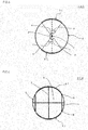
- a bonding layer 7 has a non-contact vertical linear portion 7C, and a resistance value between both end portions A and B in the non-contact vertical linear portion 7C is larger than a resistance value of a honeycomb segment 6.
- the non-contact vertical linear portion 7C is a linear portion "in which both the end portions A and B are positioned in an outer periphery of a bonded honeycomb segment assembly 4 and do not come in contact with electrode members 21 and which does not intersect with a line segment connecting centers of a pair of electrode members 21, 21 to each other".
- each of the pair of electrode members 21, 21 is formed into the band-like shape extending in the extending direction of the cells 2 of the bonded honeycomb segment assembly 4. Furthermore, in the cross section perpendicular to the extending direction of the cells 2, the one electrode member 21 in the pair of electrode members 21, 21 is disposed on the side opposite to the other electrode member 21 in the pair of electrode members 21, 21 via the center O of the bonded honeycomb segment assembly 4.
- the angle ⁇ of 0.5 times the central angle ⁇ " of the one electrode member 21 preferably has a size of 0.8 to 1.2 times and further preferably a size of 1.0 times (the same size) to "the angle ⁇ of 0.5 times the central angle ⁇ " of the other electrode member 21.
- the electrode member 21 has such a shape as obtained by curving a planar rectangular member along an outer periphery of a cylindrical shape.
- a shape obtained when the curved electrode member 21 is deformed into a planar member which is not curved will be referred to as "the planar shape" of the electrode member 21.
- the above-mentioned "planar shape" of the electrode member 21 shown in Fig. 1 to Fig. 5 is a rectangular shape.
- an outer peripheral shape of the electrode member means “the outer peripheral shape in the planar shape of the electrode member”.
- the outer peripheral shape of the electrode member 21 is "the shape in which the corner portions of the rectangular shape are formed into the curved shape" or “the shape in which the corner portions of the rectangular shape are linearly chamfered", so that the heat shock resisting properties of the honeycomb structure can further be enhanced.
- the corner portions of the electrode member have right angles, there is a tendency that stress in the vicinity of "each corner portion of the electrode member” in the bonded honeycomb segment assembly is relatively high as compared with the other portions.
- the corner portions of the electrode member are curved or linearly chamfered, it is possible to lower the stress in the vicinity of "each corner portion of the electrode member" in the bonded honeycomb segment assembly.
- the thickness of the outer peripheral wall of the bonded honeycomb segment assembly is larger than 1.0 mm, the heat shock resisting properties of the honeycomb structure deteriorate sometimes. Furthermore, when the thickness of the outer peripheral wall of the bonded honeycomb segment assembly is larger than 1.0 mm, an area of each partition wall onto which the catalyst is to be loaded is small sometimes in the case where the honeycomb structure is used as the catalyst carrier and the catalyst is loaded thereonto.
- the thickness of the outer peripheral wall is a value measured by the optical microscope.
- An average pore diameter of the electrode member 21 is preferably from 5 to 45 ⁇ m and further preferably from 7 to 40 ⁇ m.
- a suitable volume resistivity can be obtained.
- the average pore diameter of the electrode member 21 is smaller than 5 ⁇ m, the volume resistivity is excessively high sometimes.
- the average pore diameter of the electrode member 21 is larger than 40 ⁇ m, the strength of the electrode member 21 weakens and the electrode member is easily damaged.
- the average pore diameter is a value measured by the mercury porosimeter.
- binder examples include methylcellulose, hydroxypropyl methylcellulose, hydroxypropoxyl cellulose, hydroxyethylcellulose, carboxymethylcellulose, and polyvinyl alcohol. Among these examples, methylcellulose and hydroxypropoxyl cellulose are preferably used together.
- a content of the binder is preferably from 2.0 to 10.0 parts by mass, when a total mass of the silicon carbide powder and the metal silicon powder is 100 parts by mass.
- the honeycomb formed segment body is preferably dried.
- a drying condition at this time is preferably from 50 to 200°C.
- the binder similar to the binder of the forming raw material of the honeycomb segments can be used.
- a content of the binder is preferably from 0.1 to 15 parts by mass, when a total mass of the silicon carbide powder and the metal silicon powder is 100 parts by mass.
- a content of the water is preferably from 25 to 55 parts by mass, when the total mass of the silicon carbide powder and the metal silicon powder is 100 parts by mass.
- a content of the water is preferably from 15 to 60 parts by mass, when the total mass of the silicon carbide powder and the metal silicon powder is 100 parts by mass.
- the average particle diameters of the silicon carbide particles and metal silicon (metal silicon particles) are values measured by the laser diffraction method.
- the silicon carbide particles are fine particles of silicon carbide constituting the silicon carbide powder, and the metal silicon particles are fine particles of metal silicon constituting the metal silicon powder.
- a mixture obtained by mixing the silicon carbide powder (silicon carbide), metal silicon (the metal silicon powder), the binder, the surfactant, the pore former, the water and the like is preferably kneaded, to obtain the paste-like electrode member forming raw material.
- a kneading method for example, a vertical stirrer can be used.
- the bonded honeycomb segment assembly to which the electrode member forming raw material is applied is preferably dried and fired to prepare the honeycomb structure of the present invention.
- the calcinating is preferably performed to remove the binder and the like.
- the calcinating is preferably performed at 400 to 500°C in the air atmosphere for 0.5 to 20 hours.
- the firing can be performed by using an electric furnace, a gas furnace or the like.
- heating is preferably performed at 1400 to 1500°C in an inert atmosphere of nitrogen, argon or the like for one to 20 hours.
- the oxygenation treatment is preferably performed at 1200 to 1350°C for one to ten hours.
- Silicon carbide (SiC) powder and metal silicon (Si) powder were mixed at a mass ratio of 80:20. Then, to this mixture, hydroxypropyl methylcellulose as a binder and a water-absorbing resin as a pore former were added, and water was also added to prepare a forming raw material. Then, the forming raw material was kneaded by a vacuum clay kneader to prepare a columnar kneaded material. A content of the binder was 7 parts by mass when a total of the silicon carbide (SiC) powder and the metal silicon (Si) powder was 100 parts by mass.
- a content of the surfactant was 0.3 part by mass when the total of the silicon carbide (SiC) powder and the metal silicon (Si) powder was 100 parts by mass.
- a content of the water was 42 parts by mass when the total of the silicon carbide (SiC) powder and the metal silicon (Si) powder was 100 parts by mass.
- An average particle diameter of the silicon carbide powder was 52 ⁇ m, and an average particle diameter of the metal silicon powder was 6 ⁇ m.
- the average particle diameters of silicon carbide and metal silicon are values measured by the laser diffraction method. The kneading was performed by using a vertical stirrer.
- the bonded honeycomb segment precursor to which the electrode member forming raw material was applied was degreased, fired and further subjected to an oxidation treatment to obtain a honeycomb structure.
- Degreasing conditions were 550°C and three hours.
- Firing conditions were an argon atmosphere, 1450°C and two hours.
- Conditions of the oxidation treatment were 1300°C and one hour.
- the firing was only performed on "the bonded honeycomb segment precursor to which the electrode member forming raw material was applied" (after the degreasing) (as described above, during the preparation of the honeycomb segments, the honeycomb segments were not fired).
- a porosity of the bonding layer was 60%, and a porosity of the outer peripheral wall was 82%.
- an average particle diameter of silicon carbide included in the honeycomb structure was 20 ⁇ m.
- the average particle diameter of silicon carbide included in the honeycomb structure was obtained by the following method. That is, the average particle diameter was obtained from an image obtained by observing cross sections and surfaces of the honeycomb segments by a scanning electron microscope (SEM). Specifically, a sample for observing "the cross section" and "the surface” was first cut out from the honeycomb segment. As to the cross section of the honeycomb segment, concaves and convexes of the cross section were filled with a resin, the cross section was further polished, and a polished surface was observed.
- the lowest temperature of the honeycomb structure body was measured, when the voltage of 200 V was applied to the obtained honeycomb structure.
- the lowest temperature of the honeycomb structure is high, it is indicated that the unevenness of the temperature distribution in the honeycomb structure is inhibited.
- the lowest temperature of the above honeycomb structure is 100°C or more, it can be considered that the unevenness of the temperature distribution in the honeycomb structure is inhibited, and further, when the lowest temperature is 150°C or more, it can be considered that the unevenness of the temperature distribution in the honeycomb structure is more suitably inhibited.
- the measurement of the lowest temperature is performed as follows. The temperatures of the following portions of the bonded honeycomb segment assembly are measured. Each of the portions is a position in the cross section perpendicular to the cell extending direction.
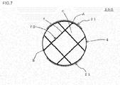
- a cell shape in Tables 1 and 2 is a shape of cells in a cross section perpendicular to an extending direction of the cells. It is to be noted that "a pattern A" of a column of a segment pattern indicates that the honeycomb structure has such a segment structure and electrode arrangement as shown in Fig. 1 to Fig. 5 . Furthermore, “a pattern B” of the column of the segment pattern indicates that the honeycomb structure has such a segment structure and electrode arrangement as shown in Fig. 7 . Furthermore, “a pattern C” of the column of the segment pattern indicates that the honeycomb structure has such a segment structure and electrode arrangement as shown in Fig. 6 .
Landscapes
- Chemical & Material Sciences (AREA)
- Engineering & Computer Science (AREA)
- Chemical Kinetics & Catalysis (AREA)
- Ceramic Engineering (AREA)
- Geometry (AREA)
- Physics & Mathematics (AREA)
- Structural Engineering (AREA)
- Materials Engineering (AREA)
- Organic Chemistry (AREA)
- Health & Medical Sciences (AREA)
- Toxicology (AREA)
- Combustion & Propulsion (AREA)
- Mechanical Engineering (AREA)
- General Engineering & Computer Science (AREA)
- Manufacturing & Machinery (AREA)
- Catalysts (AREA)
- Exhaust Gas Treatment By Means Of Catalyst (AREA)
- Exhaust Gas After Treatment (AREA)
- Ceramic Products (AREA)
Applications Claiming Priority (1)
| Application Number | Priority Date | Filing Date | Title |
|---|---|---|---|
| JP2013074936A JP5992857B2 (ja) | 2013-03-29 | 2013-03-29 | ハニカム構造体 |
Publications (3)
| Publication Number | Publication Date |
|---|---|
| EP2784047A2 true EP2784047A2 (fr) | 2014-10-01 |
| EP2784047A3 EP2784047A3 (fr) | 2015-04-08 |
| EP2784047B1 EP2784047B1 (fr) | 2018-10-10 |
Family
ID=50382365
Family Applications (1)
| Application Number | Title | Priority Date | Filing Date |
|---|---|---|---|
| EP14162314.0A Not-in-force EP2784047B1 (fr) | 2013-03-29 | 2014-03-28 | Structure en nid d'abeille |
Country Status (3)
| Country | Link |
|---|---|
| US (1) | US9255514B2 (fr) |
| EP (1) | EP2784047B1 (fr) |
| JP (1) | JP5992857B2 (fr) |
Cited By (1)
| Publication number | Priority date | Publication date | Assignee | Title |
|---|---|---|---|---|
| EP3708242A1 (fr) * | 2019-03-15 | 2020-09-16 | NGK Insulators, Ltd. | Support de type chauffage électrique, dispositif de purification de gaz d'échappement et procédé de production d'un support de type chauffage électrique |
Families Citing this family (5)
| Publication number | Priority date | Publication date | Assignee | Title |
|---|---|---|---|---|
| JP2020143597A (ja) * | 2019-03-05 | 2020-09-10 | 株式会社デンソー | 電極付きハニカム基材 |
| JP7186643B2 (ja) * | 2019-03-15 | 2022-12-09 | 日本碍子株式会社 | 電気加熱型担体、排気ガス浄化装置、電気加熱型担体の製造方法、接合体及び接合体の製造方法 |
| CN117561372A (zh) * | 2021-05-03 | 2024-02-13 | 康宁股份有限公司 | 用于排气后处理系统和组件的具有蛇形设计和选定死区的电加热器 |
| EP4559576A1 (fr) * | 2022-11-21 | 2025-05-28 | NGK Insulators, Ltd. | Élément chauffant |
| KR102910582B1 (ko) * | 2023-11-10 | 2026-01-12 | 한국기계연구원 | 배출가스 저감용 세라믹 구조체를 포함하는 배출가스 저감 장치 및 이를 사용한 배출가스 저감 방법 |
Citations (2)
| Publication number | Priority date | Publication date | Assignee | Title |
|---|---|---|---|---|
| JP2011098866A (ja) | 2009-11-06 | 2011-05-19 | Tokyo Yogyo Co Ltd | ハニカム構造体の製造方法及びハニカム構造体 |
| JP2012188958A (ja) | 2011-03-09 | 2012-10-04 | Toyota Motor Corp | 触媒コンバータ装置 |
Family Cites Families (21)
| Publication number | Priority date | Publication date | Assignee | Title |
|---|---|---|---|---|
| EP0761279B1 (fr) * | 1995-08-22 | 2002-11-20 | Denki Kagaku Kogyo Kabushiki Kaisha | Structure à nid d'abeilles |
| JP3927038B2 (ja) * | 2001-12-21 | 2007-06-06 | 日本碍子株式会社 | Si含有ハニカム構造体及びその製造方法 |
| WO2005105705A1 (fr) * | 2004-04-30 | 2005-11-10 | Ngk Insulators, Ltd. | Structure en nid d'abeille et procédé de fabrication de celle-ci |
| CN101001698B (zh) * | 2005-06-24 | 2011-02-09 | 揖斐电株式会社 | 蜂窝结构体 |
| CN100434137C (zh) * | 2005-06-24 | 2008-11-19 | 揖斐电株式会社 | 蜂窝结构体 |
| JP5037809B2 (ja) * | 2005-10-25 | 2012-10-03 | 日本碍子株式会社 | ハニカム構造体 |
| EP2006265B1 (fr) * | 2006-03-24 | 2018-01-03 | NGK Insulators, Ltd. | Corps colle |
| WO2009107230A1 (fr) * | 2008-02-29 | 2009-09-03 | イビデン株式会社 | Matière d'étanchéité pour structure en nid d'abeilles, structure en nid d'abeilles et procédé pour produire une structure en nid d'abeilles |
| WO2010092668A1 (fr) * | 2009-02-10 | 2010-08-19 | イビデン株式会社 | Matière d'étanchéité pour structure en nid-d'abeilles, structure en nid-d'abeilles et procédé de production d'une structure en nid-d'abeilles |
| JP5261256B2 (ja) * | 2009-03-30 | 2013-08-14 | 日本碍子株式会社 | 通電発熱用ハニカム体及びその製造方法 |
| EP2554265B1 (fr) | 2010-03-31 | 2017-07-26 | NGK Insulators, Ltd. | Structure de nid d'abeilles |
| WO2011125226A1 (fr) * | 2010-04-09 | 2011-10-13 | イビデン株式会社 | Structure en nid d'abeille |
| WO2011125225A1 (fr) * | 2010-04-09 | 2011-10-13 | イビデン株式会社 | Structure en nid d'abeille et dispositif de purification de gaz d'échappement |
| WO2011125228A1 (fr) * | 2010-04-09 | 2011-10-13 | イビデン株式会社 | Structure en nid d'abeille |
| WO2011125227A1 (fr) * | 2010-04-09 | 2011-10-13 | イビデン株式会社 | Structure en nid d'abeille et dispositif de purification des gaz d'échappement |
| WO2011132298A1 (fr) * | 2010-04-22 | 2011-10-27 | イビデン株式会社 | Structure alvéolaire |
| JP5612949B2 (ja) | 2010-07-28 | 2014-10-22 | 東京窯業株式会社 | ハニカム構造体及びフィルタ装置 |
| JP5691848B2 (ja) * | 2010-09-27 | 2015-04-01 | 株式会社デンソー | ハニカム構造体及び電気加熱式触媒装置 |
| JP5883299B2 (ja) * | 2011-03-24 | 2016-03-09 | 日本碍子株式会社 | 潤滑系流体の加熱用ヒーター |
| JP2012214364A (ja) * | 2011-03-28 | 2012-11-08 | Ngk Insulators Ltd | ハニカム構造体、Si−SiC系複合材料、ハニカム構造体の製造方法及びSi−SiC系複合材料の製造方法 |
| JP6022985B2 (ja) | 2013-03-29 | 2016-11-09 | 日本碍子株式会社 | ハニカム構造体 |
-
2013
- 2013-03-29 JP JP2013074936A patent/JP5992857B2/ja active Active
-
2014
- 2014-03-25 US US14/224,670 patent/US9255514B2/en active Active
- 2014-03-28 EP EP14162314.0A patent/EP2784047B1/fr not_active Not-in-force
Patent Citations (2)
| Publication number | Priority date | Publication date | Assignee | Title |
|---|---|---|---|---|
| JP2011098866A (ja) | 2009-11-06 | 2011-05-19 | Tokyo Yogyo Co Ltd | ハニカム構造体の製造方法及びハニカム構造体 |
| JP2012188958A (ja) | 2011-03-09 | 2012-10-04 | Toyota Motor Corp | 触媒コンバータ装置 |
Cited By (2)
| Publication number | Priority date | Publication date | Assignee | Title |
|---|---|---|---|---|
| EP3708242A1 (fr) * | 2019-03-15 | 2020-09-16 | NGK Insulators, Ltd. | Support de type chauffage électrique, dispositif de purification de gaz d'échappement et procédé de production d'un support de type chauffage électrique |
| US11092052B2 (en) | 2019-03-15 | 2021-08-17 | Ngk Insulators, Ltd. | Electric heating type support, exhaust gas purifying device, and method for producing electric heating type support |
Also Published As
| Publication number | Publication date |
|---|---|
| JP5992857B2 (ja) | 2016-09-14 |
| US20140294690A1 (en) | 2014-10-02 |
| EP2784047B1 (fr) | 2018-10-10 |
| US9255514B2 (en) | 2016-02-09 |
| EP2784047A3 (fr) | 2015-04-08 |
| JP2014198307A (ja) | 2014-10-23 |
Similar Documents
| Publication | Publication Date | Title |
|---|---|---|
| EP2832446B1 (fr) | Structure en nid d'abeilles | |
| EP2784051B1 (fr) | Structure en nid d'abeille | |
| EP2554265B1 (fr) | Structure de nid d'abeilles | |
| EP2554263B1 (fr) | Structure de nid d'abeilles | |
| EP2656902B1 (fr) | Structure en nid d'abeilles | |
| US8597585B2 (en) | Honeycomb structure | |
| EP2656900B1 (fr) | Structure en nid d'abeilles | |
| EP2540382A1 (fr) | Structure en nids d'abeilles | |
| EP2918341B1 (fr) | Structure en nid d'abeille | |
| EP2792396B1 (fr) | Structure en nid d'abeille | |
| EP2656903B1 (fr) | Structure en nid d'abeilles | |
| JP6364374B2 (ja) | ハニカム構造体、及びその製造方法 | |
| EP2784048B1 (fr) | Structure en nid d'abeille et son procédé de fabrication | |
| EP2784047B1 (fr) | Structure en nid d'abeille | |
| US9339799B2 (en) | Honeycomb structure and manufacturing method thereof | |
| EP2656901A1 (fr) | Structure en nid d'abeilles | |
| EP2784046B1 (fr) | Structure en nid d'abeille et son procédé de fabrication | |
| EP2689848A1 (fr) | Structure en nid d'abeilles |
Legal Events
| Date | Code | Title | Description |
|---|---|---|---|
| 17P | Request for examination filed |
Effective date: 20140328 |
|
| AK | Designated contracting states |
Kind code of ref document: A2 Designated state(s): AL AT BE BG CH CY CZ DE DK EE ES FI FR GB GR HR HU IE IS IT LI LT LU LV MC MK MT NL NO PL PT RO RS SE SI SK SM TR |
|
| AX | Request for extension of the european patent |
Extension state: BA ME |
|
| PUAI | Public reference made under article 153(3) epc to a published international application that has entered the european phase |
Free format text: ORIGINAL CODE: 0009012 |
|
| PUAL | Search report despatched |
Free format text: ORIGINAL CODE: 0009013 |
|
| AK | Designated contracting states |
Kind code of ref document: A3 Designated state(s): AL AT BE BG CH CY CZ DE DK EE ES FI FR GB GR HR HU IE IS IT LI LT LU LV MC MK MT NL NO PL PT RO RS SE SI SK SM TR |
|
| AX | Request for extension of the european patent |
Extension state: BA ME |
|
| RIC1 | Information provided on ipc code assigned before grant |
Ipc: C04B 37/00 20060101ALI20150227BHEP Ipc: C04B 35/565 20060101AFI20150227BHEP Ipc: C04B 38/00 20060101ALI20150227BHEP Ipc: F01N 3/28 20060101ALI20150227BHEP Ipc: F01N 3/20 20060101ALN20150227BHEP Ipc: B01D 46/24 20060101ALN20150227BHEP |
|
| R17P | Request for examination filed (corrected) |
Effective date: 20151008 |
|
| RBV | Designated contracting states (corrected) |
Designated state(s): AL AT BE BG CH CY CZ DE DK EE ES FI FR GB GR HR HU IE IS IT LI LT LU LV MC MK MT NL NO PL PT RO RS SE SI SK SM TR |
|
| STAA | Information on the status of an ep patent application or granted ep patent |
Free format text: STATUS: EXAMINATION IS IN PROGRESS |
|
| 17Q | First examination report despatched |
Effective date: 20170929 |
|
| GRAP | Despatch of communication of intention to grant a patent |
Free format text: ORIGINAL CODE: EPIDOSNIGR1 |
|
| STAA | Information on the status of an ep patent application or granted ep patent |
Free format text: STATUS: GRANT OF PATENT IS INTENDED |
|
| RIC1 | Information provided on ipc code assigned before grant |
Ipc: C04B 38/00 20060101ALI20180220BHEP Ipc: F01N 3/20 20060101ALN20180220BHEP Ipc: C04B 35/565 20060101AFI20180220BHEP Ipc: C04B 37/00 20060101ALI20180220BHEP Ipc: F01N 3/28 20060101ALI20180220BHEP Ipc: B01D 46/24 20060101ALI20180220BHEP |
|
| INTG | Intention to grant announced |
Effective date: 20180312 |
|
| GRAJ | Information related to disapproval of communication of intention to grant by the applicant or resumption of examination proceedings by the epo deleted |
Free format text: ORIGINAL CODE: EPIDOSDIGR1 |
|
| STAA | Information on the status of an ep patent application or granted ep patent |
Free format text: STATUS: EXAMINATION IS IN PROGRESS |
|
| INTC | Intention to grant announced (deleted) | ||
| GRAR | Information related to intention to grant a patent recorded |
Free format text: ORIGINAL CODE: EPIDOSNIGR71 |
|
| GRAS | Grant fee paid |
Free format text: ORIGINAL CODE: EPIDOSNIGR3 |
|
| STAA | Information on the status of an ep patent application or granted ep patent |
Free format text: STATUS: GRANT OF PATENT IS INTENDED |
|
| GRAA | (expected) grant |
Free format text: ORIGINAL CODE: 0009210 |
|
| STAA | Information on the status of an ep patent application or granted ep patent |
Free format text: STATUS: THE PATENT HAS BEEN GRANTED |
|
| RIC1 | Information provided on ipc code assigned before grant |
Ipc: C04B 38/00 20060101ALI20180815BHEP Ipc: C04B 35/565 20060101AFI20180815BHEP Ipc: F01N 3/28 20060101ALI20180815BHEP Ipc: C04B 37/00 20060101ALI20180815BHEP Ipc: B01D 46/24 20060101ALI20180815BHEP Ipc: F01N 3/20 20060101ALN20180815BHEP |
|
| INTG | Intention to grant announced |
Effective date: 20180830 |
|
| RIN1 | Information on inventor provided before grant (corrected) |
Inventor name: OMIYA, YOSHIMASA Inventor name: MASE, KAZUMI Inventor name: KANEDA, ATSUSHI |
|
| AK | Designated contracting states |
Kind code of ref document: B1 Designated state(s): AL AT BE BG CH CY CZ DE DK EE ES FI FR GB GR HR HU IE IS IT LI LT LU LV MC MK MT NL NO PL PT RO RS SE SI SK SM TR |
|
| REG | Reference to a national code |
Ref country code: GB Ref legal event code: FG4D |
|
| REG | Reference to a national code |
Ref country code: CH Ref legal event code: EP Ref country code: AT Ref legal event code: REF Ref document number: 1051031 Country of ref document: AT Kind code of ref document: T Effective date: 20181015 |
|
| REG | Reference to a national code |
Ref country code: IE Ref legal event code: FG4D |
|
| REG | Reference to a national code |
Ref country code: DE Ref legal event code: R096 Ref document number: 602014033649 Country of ref document: DE |
|
| REG | Reference to a national code |
Ref country code: NL Ref legal event code: MP Effective date: 20181010 |
|
| REG | Reference to a national code |
Ref country code: LT Ref legal event code: MG4D |
|
| REG | Reference to a national code |
Ref country code: AT Ref legal event code: MK05 Ref document number: 1051031 Country of ref document: AT Kind code of ref document: T Effective date: 20181010 |
|
| PG25 | Lapsed in a contracting state [announced via postgrant information from national office to epo] |
Ref country code: NL Free format text: LAPSE BECAUSE OF FAILURE TO SUBMIT A TRANSLATION OF THE DESCRIPTION OR TO PAY THE FEE WITHIN THE PRESCRIBED TIME-LIMIT Effective date: 20181010 |
|
| PG25 | Lapsed in a contracting state [announced via postgrant information from national office to epo] |
Ref country code: FI Free format text: LAPSE BECAUSE OF FAILURE TO SUBMIT A TRANSLATION OF THE DESCRIPTION OR TO PAY THE FEE WITHIN THE PRESCRIBED TIME-LIMIT Effective date: 20181010 Ref country code: NO Free format text: LAPSE BECAUSE OF FAILURE TO SUBMIT A TRANSLATION OF THE DESCRIPTION OR TO PAY THE FEE WITHIN THE PRESCRIBED TIME-LIMIT Effective date: 20190110 Ref country code: IS Free format text: LAPSE BECAUSE OF FAILURE TO SUBMIT A TRANSLATION OF THE DESCRIPTION OR TO PAY THE FEE WITHIN THE PRESCRIBED TIME-LIMIT Effective date: 20190210 Ref country code: AT Free format text: LAPSE BECAUSE OF FAILURE TO SUBMIT A TRANSLATION OF THE DESCRIPTION OR TO PAY THE FEE WITHIN THE PRESCRIBED TIME-LIMIT Effective date: 20181010 Ref country code: LV Free format text: LAPSE BECAUSE OF FAILURE TO SUBMIT A TRANSLATION OF THE DESCRIPTION OR TO PAY THE FEE WITHIN THE PRESCRIBED TIME-LIMIT Effective date: 20181010 Ref country code: ES Free format text: LAPSE BECAUSE OF FAILURE TO SUBMIT A TRANSLATION OF THE DESCRIPTION OR TO PAY THE FEE WITHIN THE PRESCRIBED TIME-LIMIT Effective date: 20181010 Ref country code: LT Free format text: LAPSE BECAUSE OF FAILURE TO SUBMIT A TRANSLATION OF THE DESCRIPTION OR TO PAY THE FEE WITHIN THE PRESCRIBED TIME-LIMIT Effective date: 20181010 Ref country code: BG Free format text: LAPSE BECAUSE OF FAILURE TO SUBMIT A TRANSLATION OF THE DESCRIPTION OR TO PAY THE FEE WITHIN THE PRESCRIBED TIME-LIMIT Effective date: 20190110 Ref country code: PL Free format text: LAPSE BECAUSE OF FAILURE TO SUBMIT A TRANSLATION OF THE DESCRIPTION OR TO PAY THE FEE WITHIN THE PRESCRIBED TIME-LIMIT Effective date: 20181010 Ref country code: HR Free format text: LAPSE BECAUSE OF FAILURE TO SUBMIT A TRANSLATION OF THE DESCRIPTION OR TO PAY THE FEE WITHIN THE PRESCRIBED TIME-LIMIT Effective date: 20181010 |
|
| PG25 | Lapsed in a contracting state [announced via postgrant information from national office to epo] |
Ref country code: AL Free format text: LAPSE BECAUSE OF FAILURE TO SUBMIT A TRANSLATION OF THE DESCRIPTION OR TO PAY THE FEE WITHIN THE PRESCRIBED TIME-LIMIT Effective date: 20181010 Ref country code: PT Free format text: LAPSE BECAUSE OF FAILURE TO SUBMIT A TRANSLATION OF THE DESCRIPTION OR TO PAY THE FEE WITHIN THE PRESCRIBED TIME-LIMIT Effective date: 20190210 Ref country code: SE Free format text: LAPSE BECAUSE OF FAILURE TO SUBMIT A TRANSLATION OF THE DESCRIPTION OR TO PAY THE FEE WITHIN THE PRESCRIBED TIME-LIMIT Effective date: 20181010 Ref country code: RS Free format text: LAPSE BECAUSE OF FAILURE TO SUBMIT A TRANSLATION OF THE DESCRIPTION OR TO PAY THE FEE WITHIN THE PRESCRIBED TIME-LIMIT Effective date: 20181010 Ref country code: GR Free format text: LAPSE BECAUSE OF FAILURE TO SUBMIT A TRANSLATION OF THE DESCRIPTION OR TO PAY THE FEE WITHIN THE PRESCRIBED TIME-LIMIT Effective date: 20190111 |
|
| REG | Reference to a national code |
Ref country code: DE Ref legal event code: R097 Ref document number: 602014033649 Country of ref document: DE |
|
| PG25 | Lapsed in a contracting state [announced via postgrant information from national office to epo] |
Ref country code: CZ Free format text: LAPSE BECAUSE OF FAILURE TO SUBMIT A TRANSLATION OF THE DESCRIPTION OR TO PAY THE FEE WITHIN THE PRESCRIBED TIME-LIMIT Effective date: 20181010 Ref country code: IT Free format text: LAPSE BECAUSE OF FAILURE TO SUBMIT A TRANSLATION OF THE DESCRIPTION OR TO PAY THE FEE WITHIN THE PRESCRIBED TIME-LIMIT Effective date: 20181010 Ref country code: DK Free format text: LAPSE BECAUSE OF FAILURE TO SUBMIT A TRANSLATION OF THE DESCRIPTION OR TO PAY THE FEE WITHIN THE PRESCRIBED TIME-LIMIT Effective date: 20181010 |
|
| PLBE | No opposition filed within time limit |
Free format text: ORIGINAL CODE: 0009261 |
|
| STAA | Information on the status of an ep patent application or granted ep patent |
Free format text: STATUS: NO OPPOSITION FILED WITHIN TIME LIMIT |
|
| PG25 | Lapsed in a contracting state [announced via postgrant information from national office to epo] |
Ref country code: EE Free format text: LAPSE BECAUSE OF FAILURE TO SUBMIT A TRANSLATION OF THE DESCRIPTION OR TO PAY THE FEE WITHIN THE PRESCRIBED TIME-LIMIT Effective date: 20181010 Ref country code: SM Free format text: LAPSE BECAUSE OF FAILURE TO SUBMIT A TRANSLATION OF THE DESCRIPTION OR TO PAY THE FEE WITHIN THE PRESCRIBED TIME-LIMIT Effective date: 20181010 Ref country code: RO Free format text: LAPSE BECAUSE OF FAILURE TO SUBMIT A TRANSLATION OF THE DESCRIPTION OR TO PAY THE FEE WITHIN THE PRESCRIBED TIME-LIMIT Effective date: 20181010 Ref country code: SK Free format text: LAPSE BECAUSE OF FAILURE TO SUBMIT A TRANSLATION OF THE DESCRIPTION OR TO PAY THE FEE WITHIN THE PRESCRIBED TIME-LIMIT Effective date: 20181010 |
|
| 26N | No opposition filed |
Effective date: 20190711 |
|
| PG25 | Lapsed in a contracting state [announced via postgrant information from national office to epo] |
Ref country code: MC Free format text: LAPSE BECAUSE OF FAILURE TO SUBMIT A TRANSLATION OF THE DESCRIPTION OR TO PAY THE FEE WITHIN THE PRESCRIBED TIME-LIMIT Effective date: 20181010 Ref country code: SI Free format text: LAPSE BECAUSE OF FAILURE TO SUBMIT A TRANSLATION OF THE DESCRIPTION OR TO PAY THE FEE WITHIN THE PRESCRIBED TIME-LIMIT Effective date: 20181010 |
|
| REG | Reference to a national code |
Ref country code: CH Ref legal event code: PL |
|
| GBPC | Gb: european patent ceased through non-payment of renewal fee |
Effective date: 20190328 |
|
| PG25 | Lapsed in a contracting state [announced via postgrant information from national office to epo] |
Ref country code: LU Free format text: LAPSE BECAUSE OF NON-PAYMENT OF DUE FEES Effective date: 20190328 |
|
| REG | Reference to a national code |
Ref country code: BE Ref legal event code: MM Effective date: 20190331 |
|
| PG25 | Lapsed in a contracting state [announced via postgrant information from national office to epo] |
Ref country code: CH Free format text: LAPSE BECAUSE OF NON-PAYMENT OF DUE FEES Effective date: 20190331 Ref country code: GB Free format text: LAPSE BECAUSE OF NON-PAYMENT OF DUE FEES Effective date: 20190328 Ref country code: LI Free format text: LAPSE BECAUSE OF NON-PAYMENT OF DUE FEES Effective date: 20190331 Ref country code: IE Free format text: LAPSE BECAUSE OF NON-PAYMENT OF DUE FEES Effective date: 20190328 |
|
| PG25 | Lapsed in a contracting state [announced via postgrant information from national office to epo] |
Ref country code: BE Free format text: LAPSE BECAUSE OF NON-PAYMENT OF DUE FEES Effective date: 20190331 Ref country code: FR Free format text: LAPSE BECAUSE OF NON-PAYMENT OF DUE FEES Effective date: 20190331 |
|
| PG25 | Lapsed in a contracting state [announced via postgrant information from national office to epo] |
Ref country code: TR Free format text: LAPSE BECAUSE OF FAILURE TO SUBMIT A TRANSLATION OF THE DESCRIPTION OR TO PAY THE FEE WITHIN THE PRESCRIBED TIME-LIMIT Effective date: 20181010 |
|
| PG25 | Lapsed in a contracting state [announced via postgrant information from national office to epo] |
Ref country code: MT Free format text: LAPSE BECAUSE OF NON-PAYMENT OF DUE FEES Effective date: 20190328 |
|
| PG25 | Lapsed in a contracting state [announced via postgrant information from national office to epo] |
Ref country code: CY Free format text: LAPSE BECAUSE OF FAILURE TO SUBMIT A TRANSLATION OF THE DESCRIPTION OR TO PAY THE FEE WITHIN THE PRESCRIBED TIME-LIMIT Effective date: 20181010 |
|
| PG25 | Lapsed in a contracting state [announced via postgrant information from national office to epo] |
Ref country code: HU Free format text: LAPSE BECAUSE OF FAILURE TO SUBMIT A TRANSLATION OF THE DESCRIPTION OR TO PAY THE FEE WITHIN THE PRESCRIBED TIME-LIMIT; INVALID AB INITIO Effective date: 20140328 |
|
| PG25 | Lapsed in a contracting state [announced via postgrant information from national office to epo] |
Ref country code: MK Free format text: LAPSE BECAUSE OF FAILURE TO SUBMIT A TRANSLATION OF THE DESCRIPTION OR TO PAY THE FEE WITHIN THE PRESCRIBED TIME-LIMIT Effective date: 20181010 |
|
| PGFP | Annual fee paid to national office [announced via postgrant information from national office to epo] |
Ref country code: DE Payment date: 20240130 Year of fee payment: 11 |
|
| REG | Reference to a national code |
Ref country code: DE Ref legal event code: R119 Ref document number: 602014033649 Country of ref document: DE |
|
| PG25 | Lapsed in a contracting state [announced via postgrant information from national office to epo] |
Ref country code: DE Free format text: LAPSE BECAUSE OF NON-PAYMENT OF DUE FEES Effective date: 20251001 |