EP2784235A1 - Système de plafond suspendu, plafond suspendu et utilisation du système de plafond suspendu pour fabriquer un plafond suspendu - Google Patents
Système de plafond suspendu, plafond suspendu et utilisation du système de plafond suspendu pour fabriquer un plafond suspendu Download PDFInfo
- Publication number
- EP2784235A1 EP2784235A1 EP20140161677 EP14161677A EP2784235A1 EP 2784235 A1 EP2784235 A1 EP 2784235A1 EP 20140161677 EP20140161677 EP 20140161677 EP 14161677 A EP14161677 A EP 14161677A EP 2784235 A1 EP2784235 A1 EP 2784235A1
- Authority
- EP
- European Patent Office
- Prior art keywords
- end part
- suspended ceiling
- suspension
- suspension opening
- butted end
- Prior art date
- Legal status (The legal status is an assumption and is not a legal conclusion. Google has not performed a legal analysis and makes no representation as to the accuracy of the status listed.)
- Granted
Links
Images




Classifications
-
- E—FIXED CONSTRUCTIONS
- E04—BUILDING
- E04B—GENERAL BUILDING CONSTRUCTIONS; WALLS, e.g. PARTITIONS; ROOFS; FLOORS; CEILINGS; INSULATION OR OTHER PROTECTION OF BUILDINGS
- E04B9/00—Ceilings; Construction of ceilings, e.g. false ceilings; Ceiling construction with regard to insulation
- E04B9/06—Ceilings; Construction of ceilings, e.g. false ceilings; Ceiling construction with regard to insulation characterised by constructional features of the supporting construction, e.g. cross section or material of framework members
- E04B9/065—Ceilings; Construction of ceilings, e.g. false ceilings; Ceiling construction with regard to insulation characterised by constructional features of the supporting construction, e.g. cross section or material of framework members comprising supporting beams having a folded cross-section
- E04B9/067—Ceilings; Construction of ceilings, e.g. false ceilings; Ceiling construction with regard to insulation characterised by constructional features of the supporting construction, e.g. cross section or material of framework members comprising supporting beams having a folded cross-section with inverted T-shaped cross-section
- E04B9/068—Ceilings; Construction of ceilings, e.g. false ceilings; Ceiling construction with regard to insulation characterised by constructional features of the supporting construction, e.g. cross section or material of framework members comprising supporting beams having a folded cross-section with inverted T-shaped cross-section with double web
-
- E—FIXED CONSTRUCTIONS
- E04—BUILDING
- E04B—GENERAL BUILDING CONSTRUCTIONS; WALLS, e.g. PARTITIONS; ROOFS; FLOORS; CEILINGS; INSULATION OR OTHER PROTECTION OF BUILDINGS
- E04B9/00—Ceilings; Construction of ceilings, e.g. false ceilings; Ceiling construction with regard to insulation
- E04B9/18—Means for suspending the supporting construction
- E04B9/20—Means for suspending the supporting construction adjustable
- E04B9/205—Means for suspending the supporting construction adjustable by means of a resilient clip
Definitions
- the current invention relates to a suspended ceiling system according to the preamble of the first claim.
- the present invention also relates to a suspended ceiling comprising the suspended ceiling system according to the invention and use of the suspended ceiling system for making the suspended ceiling.
- US2004/0111995 A1 and EP512614A1 for example describe a suspended ceiling system for making a suspended ceiling.
- the suspended ceiling system comprises a wire hanger for suspending the suspended ceiling and a runner with a suspension opening.
- the wire hanger comprises suspension hooks at its end parts for hooking into the suspension opening of the runner of the suspended ceiling at one side and for further attachment to the construction at the other side.
- a rotating movement having its axis of rotation along length direction of the runner is required.
- one of the suspension hooks comprises a butted end part for attaching the suspension hook to the construction supporting the suspended ceiling.
- US5845454A describes a suspended ceiling system in which a butted end part is received by the suspension opening by for example pushing the butted end part through the suspension opening along a pushing direction which is perpendicular to the suspension opening.
- the hook can unwantedly leave the suspension opening in a relative easy way, for example by pulling the hook out of the suspension opening along the pushing direction, for example during mounting of other runners to the suspended ceiling, while working on the suspended ceiling, during an earthquake, etc.
- the runner comprises a suspension opening provided to receive the butted end part of the suspension hook.
- the wire hanger comprises a standing part adjacent to the end part of the wire hanger.
- the standing part is provided such that when the runner is hooked to the wire hanger at the suspension opening, the runner is located in between the butted end part and the standing part.
- An extending part of the suspension hook in between the butted end part and the standing part in such configuration protrudes through the suspension opening.
- the butted end part and the suspension opening are provided such that the suspension opening is provided to receive the butted end part of the suspension hook in a rotational movement with an axis of rotation along the standing part.
- a rotational movement of the suspension hook has been found to be easy to perform and requires less complicated movements for the installer installing the suspended ceiling when compared to a rotational movement with an axis of rotation which is, for example, perpendicular to the standing part and for example is positioned along the runner.
- it is avoided by the shape of the butted end part more in particular by the overlapping part of the butted end part overlapping with the at least part of the runner surrounding the suspension opening, and the suspension opening that the butted end part leaves the suspension opening unwantedly in a movement along a direction substantially perpendicular to the suspension opening.
- the butted end part of the suspension hook of the wire hanger has a diameter which is larger than the diameter of the remainder of the wire hanger. More preferably, the butted end part of the wire hanger outwardly extends from the remainder of the wire hanger, preferably towards a direction opposing the gravitational direction. In this way, after moving the butted end part through the suspension opening, gravitation pulls down on the runner such that the suspension opening moves with respect to the butted end part such that part of the butted end part now faces the part of the runner surrounding the suspension opening preventing wire hanger from leaving the suspension opening.
- the increase in diameter with respect to the remainder of the wire hanger is substantially abrupt such as to further prevent the butted end part from unwontedly moving back through the suspension opening.
- the rotational movement can be facilitated when the cross section of the butted end part along a plane comprising the standing and the extending part, which preferably is the largest cross section, fits in the suspension opening.
- the cross section of the butted end part along the plane comprising the standing and the extending part fits in the suspension opening when the standing part is positioned substantially along the gravitational direction and the runner is substantially horizontal.
- the movements required by the installer installing the suspended ceiling can be further facilitated as even less movements are required.
- the wire hangers can be suspended to the structure in which the suspended ceiling is desired to be hung after which the runners are mounted to the wire hangers without having to perform elaborate movements with the wire hangers, limiting the time needed to mount the runners and thus the suspended ceiling and further for example limiting the risk that the wire hangers leave their suspended configuration due to the further manipulations of the installer.
- the butted end part comprises part of the outer surface of a sphere, preferably a spherical cap, the centre of the sphere being positioned substantially at the intersection of the standing part and the extending part.
- a configuration of the butted end part for example allows that by rotation of the butted end part with an axis of rotation along the standing part, the butted end part will be able to rotate through the suspension opening.
- alternative shapes for the butted end part are possible, the shape has been found relatively easy to make.
- the butted end part is in the form of a truncated cone. It has been found that with such a truncated cone a good interconnection between the suspension opening and the wire hanger can be achieved. Such truncated cone has for example been found to be easily pushable into the suspension opening whereas sufficiently preventing the butted end part from unwantedly leaving the opening especially when using a snap-fit connection. Moreover, the truncated shape allows that the protrusion of the wire hanger through the suspension opening is reduced, further decreasing the risk that ceiling tiles supported by the runner are hindered.
- the suspension opening comprises a first suspension opening part with first dimensions allowing transfer of the butted end part through the suspension opening and a second suspension opening part with second more limited dimensions for preventing removal of the butted end part from the suspension opening.
- transfer of the butted end part through the suspension opening more in particular the first suspension opening part, is done along a first direction, for example by pushing the butted end part through the first suspension opening part, by tilting the butted end part through the first suspension opening part, etc.
- Moving the butted end part of the suspension hook through the first suspension opening part can be done, although not crucial for the invention, in a snap-fit way such as to further reduce the risk that the butted end part of the suspension hook unwantedly leaves the suspension opening.
- the butted end part is subsequently moved towards the second suspension opening part along a second direction such that the suspension hook protrudes through the second suspension opening part, the limited dimensions of the second suspension opening part preventing the unwanted removal of the butted end part from the suspension opening.
- the first direction and the second direction are different from each other such as to further reduce the risk that the butted end part unwontedly leaves the suspension opening of the runner.
- the dimensions of the opening between the first and the second suspension opening part is provided to allow at least part of the wire hanger to pass, although not critical for the invention the passing of the part of the wire hanger through the opening between the first and the second suspension opening part can be in a snap-fit connection.
- the first suspension opening part is positioned below the second suspension opening part along gravitation direction.
- the butted end part after having pushed the butted end part through the first suspension opening part, the butted end part is forced to the second suspension opening part by means of gravity, further reducing the risk that the butted end part unwantedly moves back to the first suspension opening part and there unwantedly leaves the first suspension opening part.
- the first suspension opening part may be provided to receive the butted end part in a snap-fit connection such as to further reduce the risk that the butted end part of the suspension hook unwantedly leaves the suspension opening.
- the first suspension opening part comprises at least one slit outwardly radiating from the edge of the first suspension opening part, the slit providing resilient properties to the edge of the first opening for providing the snap-fit connection.
- the slits can be provided in any way deemed appropriate by the person skilled in the art.
- the first and/or the second suspension opening part are substantially circular and adjacent to each other.
- such configuration is preferred and allows an easy creation, for example, by punching through part of the runner at the desired location of the suspension opening, such configuration is not critical for the invention and can be determined by the person skilled in the art.
- the first and the second suspension opening are substantially circular and the diameter of the second opening is smaller than the diameter of the first opening and more preferably substantially equals, or equals, the diameter of the wire hanger.
- the suspension opening is a triangle, especially when the butted end part and the suspension opening are provided such that the suspension opening is provided to receive the butted end part of the suspension hook in a rotational movement with an axis of rotation extending along the standing part.
- such suspension opening allows a relative easy throughput of the butted end part through the suspension opening while at the same time decreasing the risk that the butted end part unwantedly leaves the suspension opening as the part of the butted end part facing the part of the runner surrounding the suspension opening and preventing wire hanger from leaving the suspension opening is enlarged, especially if the upper angle of the triangle is acute, for example when the triangle itself is an acute triangle.
- An example of an acute triangle for example is an equilateral, or a substantially equilateral, triangle.
- one of the heights of the acute triangle is positioned substantially along gravitational direction such that one of the angles of the triangle is positioned in an upper position improving guidance of the extending part of the wire hanger towards that angle.
- the invention also relates to a suspended ceiling comprising the suspended ceiling system according to the invention.
- the suspension opening of the runner receives the butted end part of the hook with the suspension hook partly protruding through the suspension opening with the butted end part and the opposing end part of the suspension hook located at opposing sides of the suspension opening.
- the butted part hooks behind an edge of the suspension opening such as to prevent the butted end part of the hook from leaving the opening.
- the runner is a T-runner comprising a bead along the upper edge of its upright web.
- T-runner comprising a bead along the upper edge of its upright web.
- bandraster systems are also possible.
- the extending part of the suspension hook in between the butted end part and the standing part protruding through the suspension opening has a length which is at least half of the width of the bead of the runner. More preferably, the length of the standing part protruding through the suspension opening and the dimensions of the butted end part are adapted such that the butted end part does not substantially extend beyond the bead when mounted to the runner such that the risk that the wire hanger interferes with ceiling tiles positioned on the runner is reduced.
- the invention also relates to the use of a suspended ceiling system according to the current invention for making a suspended ceiling according to the current invention.
- the suspension hook is hooked into the suspension opening of the runner of the suspended ceiling system according to the invention by transferring a butted end part of the suspension hook through the suspension opening in a rotational movement with an axis of rotation extending along the standing part.
- Figure 1 shows a suspended ceiling according to the present invention.
- the suspended ceiling 2 shown in figure 1 is made from a suspended ceiling system 1 according to the invention.
- the suspended ceiling system 1 for making the suspended ceiling 2 comprises a wire hanger 3 for suspending the suspended ceiling 2, more in particular a runner 6 of the suspended ceiling 2.
- the wire hanger 3 comprises a suspension hook 4 at an end part 8 of the wire hanger 3 for hooking into a suspension opening 5 of the runner 6 of the suspended ceiling 2.
- the suspension hook 4 comprises a butted end part 7.
- the wire hanger 3 preferably further comprises a standing part 9 adjacent to the end part 8 of the wire hanger 3.
- the standing part 9 is such that the runner 6, when hooked to the wire hanger 3, at the suspension opening 5 is located in between the butted end part 7 and the standing part 9.
- the standing part 9 often is a vertical part of the wire hanger 3.
- the wire hanger 3 further preferably comprises an extending part 10 of the suspension hook 4 in between the butted end part 7 and the standing part 9 protruding through the suspension opening 5, as also shown in figure 1 .
- the wire hanger 3, and more precisely the standing part 9, the suspension hook 4 with the butted end part 7 and the extending part 10 at the end part 8, is made from a wire, preferably a bent wire.
- the wire preferably is a metal wire, for example a steel wire or even a stainless steel wire or a galvanized steel, for example having a thickness of about 4 mm depending on the desired use of the wire.
- the butted end part 7 preferably is made by butting, a process which is known for making, for example, metal bucket carrying handles often called bails often for plastic buckets.
- the wire hanger 3 shown in figure 1 further is attached to a further wire hanger 18 having a further suspension hook 19 using a wire hanger clamp 17.
- a wire hanger clamp 17 and further wire hanger 18 allow the adjustment of the height from which the suspended ceiling suspends from the ceiling of the structure to which it is suspended.
- Such configuration is however not critical to the current invention, as the wire hanger 3 can be provided with a further suspension hook 19 at a further end part 20 opposing the end part 8.
- the clamp 17 for example is made from steel, for example galvanized steel, spring steel, preferably galvanized spring steel.
- the butted end part 7 and the suspension opening 5 are adapted to each other such that the suspension opening 5 is provided to receive the butted end part 7 of the suspension hook 4.
- This is for example shown in figure 4 in which the cross-section of the butted end part 7 and the suspension opening 5 are compared such that it can be observed that the butted end part 7 fits inside the suspension opening 5.
- the cross section of the butted end part 7 extending along a plane comprising the standing 9 and the extending part 10 fits in the suspension opening 5.
- figure 4 shows that the cross section of the butted end part 7 extending along a plane comprising the standing and the extending part 10 fits in the suspension opening 5 when the standing part 9 is positioned substantially along the gravitational direction and the runner 6 is substantially horizontal.
- Figure 4 further shows that the butted end part 7 comprises part of the outer surface of a sphere, in particular as shown in figure 4 a spherical cap.
- the centre of the sphere preferably is positioned substantially, or positioned, at the intersection 13 of the standing part 9 and the extending part 10.
- butted end part 7 has benefits with respect to providing the butted end part 7 through the suspension opening 5, as will be explained further down, and the way of manufacturing the butted end part 7 having such a shape can be performed relatively easy, such shape is not critical for the invention and can be further adapted depending on the desired application by the person skilled in the art.
- the butted end part 7 can for example have the shape of an ellipse, a cone, a truncated cone, a pyramid, etc.
- the runner 6 of the suspended ceiling system 1 and eventually of the suspended ceiling 2, for example is a known T-shaped, for example metal, runner, as for example shown in the figures.
- a runner 6 has an upright web 15 with a bead 14 along its upper edge and a supporting web 16, provided to support ceiling tiles, not shown for clarity sake.
- the suspension opening 15 is provided in the upright web 15, as shown in the figures.
- the ceiling tiles supported by the runner 6 can be any type of ceiling tile deemed appropriate by the person skilled in the art such as for example a mineral wool ceiling tile.
- other types of ceiling tile are possible such as for example metal ceiling tiles, wood ceiling tiles, etc.
- the suspension opening 5 is a triangle, more specifically an acute triangle. More specifically, one of the heights of the acute triangle is positioned substantially along gravitational direction. This is however not critical for the invention and other shapes can be devised by the person skilled in the art keeping in mind that the butted end part 7 is to be received in the suspension opening 5.
- the suspension opening 5 of the runner 6 receives the butted end part 7 of the suspension hook 4 with the suspension hook 4 partly protruding through the suspension opening 5 with the butted end part 7 and the opposing end part 8 of the suspension hook 4 located at opposing sides of the suspension opening 5.
- This is for example shown in more detail in figure 7 .
- the butted part preferably hooks behind an edge of the suspension opening 5 such as to prevent the butted end part 7 of the hook from leaving the opening.
- the runner 6 at the suspension opening 5 is located in between the butted end part 7 and the standing part 9, the extending part 10 of the suspension hook 4 in between the butted end part 7 and the standing part 9 protruding through the suspension opening 5.
- the extending part 10 has a length of at least half of the width of the bead 14 of the runner 6.
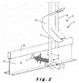
- Figure 2 shows a first step of mounting the wire hanger 3 to the runner 6 in which step the wire hanger 3 is brought closer to the runner 6 with the butted end part 7 oriented such that plane comprising the standing part 9 and the extending part 10 is substantially parallel to the upright web 15 of the runner 6.
- Figure 3 shows a result of such positioning along a direction along the upright web 15 of the runner 6.
- Figure 4 shows an overview of the configuration of figure 3 along a direction perpendicular to the direction of the upright web 15 of the runner 6.
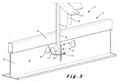
- Figure 5 shows the rotational movement 11 of the butted end part 7 with an axis of rotation 12 extending along the standing part 9. As indicated in figure 4 when comparing the cross section of the butted end part 7 and the dimensions of the suspension opening 5, such rotational movement 11 is allowed and will move the butted end part 7 through the suspension opening 5.
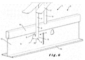
- Figure 6 shows the result of the rotational movement 11 in which the butted end part 7 has fully rotated through the suspension opening 5. It can be seen that although the butted end part 7 was allowed through the suspension opening 5 by the rotating movement 11, it is prevented from leaving the suspension opening along a linear movement, for example a retracting movement back through the suspension opening 5 due to the dimensions of the suspension opening 5. Indeed, it can be seen that the largest cross section of the butted end part 7 extending along a plane substantially parallel to the suspension opening 5 overlaps with at least part of the runner 6 surrounding the suspension opening 5 when the standing part 9 is positioned substantially along the gravitational direction and the runner 6 is substantially horizontal, for every position of the extending part 10 protruding substantially perpendicularly through the suspension opening 5.
- Figure 7 shows that due to the shape of the suspension opening, which tapers along a direction opposing gravitational direction, the risk that the butted end part 7 unwantedly leaves the suspension opening 5 is further reduced.
Landscapes
- Engineering & Computer Science (AREA)
- Architecture (AREA)
- Physics & Mathematics (AREA)
- Electromagnetism (AREA)
- Civil Engineering (AREA)
- Structural Engineering (AREA)
- Curtains And Furnishings For Windows Or Doors (AREA)
- Mirrors, Picture Frames, Photograph Stands, And Related Fastening Devices (AREA)
Priority Applications (1)
| Application Number | Priority Date | Filing Date | Title |
|---|---|---|---|
| EP14161677.1A EP2784235B8 (fr) | 2013-03-26 | 2014-03-26 | Système de plafond suspendu, plafond suspendu et utilisation du système de plafond suspendu pour fabriquer un plafond suspendu |
Applications Claiming Priority (2)
| Application Number | Priority Date | Filing Date | Title |
|---|---|---|---|
| EP13161068 | 2013-03-26 | ||
| EP14161677.1A EP2784235B8 (fr) | 2013-03-26 | 2014-03-26 | Système de plafond suspendu, plafond suspendu et utilisation du système de plafond suspendu pour fabriquer un plafond suspendu |
Publications (3)
| Publication Number | Publication Date |
|---|---|
| EP2784235A1 true EP2784235A1 (fr) | 2014-10-01 |
| EP2784235B1 EP2784235B1 (fr) | 2016-06-29 |
| EP2784235B8 EP2784235B8 (fr) | 2024-05-01 |
Family
ID=47915596
Family Applications (1)
| Application Number | Title | Priority Date | Filing Date |
|---|---|---|---|
| EP14161677.1A Active EP2784235B8 (fr) | 2013-03-26 | 2014-03-26 | Système de plafond suspendu, plafond suspendu et utilisation du système de plafond suspendu pour fabriquer un plafond suspendu |
Country Status (4)
| Country | Link |
|---|---|
| EP (1) | EP2784235B8 (fr) |
| DK (1) | DK2784235T3 (fr) |
| ES (1) | ES2589116T3 (fr) |
| PL (1) | PL2784235T3 (fr) |
Cited By (11)
| Publication number | Priority date | Publication date | Assignee | Title |
|---|---|---|---|---|
| CN104847048A (zh) * | 2015-05-28 | 2015-08-19 | 广州市广京装饰材料有限公司 | 天花龙骨结构及安装方法 |
| JP2017197932A (ja) * | 2016-04-26 | 2017-11-02 | 株式会社ケーワン | 天井下地構造及び吊り部材 |
| CN109138256A (zh) * | 2018-09-27 | 2019-01-04 | 广州康普顿至高建材有限公司 | 一种活动式片状垂吊天花 |
| US20190085559A1 (en) * | 2017-09-21 | 2019-03-21 | Armstrong World Industries, Inc. | Ceiling system |
| CN109537793A (zh) * | 2018-12-06 | 2019-03-29 | 河南三阳建材科技有限公司 | 便于安装调平的吊顶结构及其安装方法 |
| CN109680860A (zh) * | 2019-01-22 | 2019-04-26 | 杭州柏晗装饰设计工程有限公司 | 一种硅钙板吊顶 |
| CN109680859A (zh) * | 2019-01-22 | 2019-04-26 | 杭州柏晗装饰设计工程有限公司 | 一种铝扣板吊顶 |
| CN110700475A (zh) * | 2019-09-18 | 2020-01-17 | 上海金茂建筑装饰有限公司 | 装配式天花板吊顶梁结构及其装配方法 |
| CN111042427A (zh) * | 2019-12-30 | 2020-04-21 | 成都劲启材料科技有限公司 | 吊顶扣件及其吊顶机构 |
| CN114277999A (zh) * | 2022-01-12 | 2022-04-05 | 浙江亚厦装饰股份有限公司 | 一种装配式几字形龙骨吊顶结构及其安装方法 |
| CN115162605A (zh) * | 2022-07-14 | 2022-10-11 | 正兴建设集团股份有限公司 | 一种吊顶的纵向调节机构及施工方法 |
Citations (3)
| Publication number | Priority date | Publication date | Assignee | Title |
|---|---|---|---|---|
| EP0512614A1 (fr) | 1991-05-03 | 1992-11-11 | BLIEKENDAAL, Jacobus Albertus Paulus | Organe de suspension et crochet pour ledit organe |
| US5845454A (en) | 1996-04-23 | 1998-12-08 | Malizia; John T. | Drop ceiling hanging system |
| US20040111995A1 (en) | 2002-12-09 | 2004-06-17 | Forrest Dockery | Hanger system |
-
2014
- 2014-03-26 EP EP14161677.1A patent/EP2784235B8/fr active Active
- 2014-03-26 PL PL14161677.1T patent/PL2784235T3/pl unknown
- 2014-03-26 DK DK14161677.1T patent/DK2784235T3/en active
- 2014-03-26 ES ES14161677.1T patent/ES2589116T3/es active Active
Patent Citations (3)
| Publication number | Priority date | Publication date | Assignee | Title |
|---|---|---|---|---|
| EP0512614A1 (fr) | 1991-05-03 | 1992-11-11 | BLIEKENDAAL, Jacobus Albertus Paulus | Organe de suspension et crochet pour ledit organe |
| US5845454A (en) | 1996-04-23 | 1998-12-08 | Malizia; John T. | Drop ceiling hanging system |
| US20040111995A1 (en) | 2002-12-09 | 2004-06-17 | Forrest Dockery | Hanger system |
Cited By (18)
| Publication number | Priority date | Publication date | Assignee | Title |
|---|---|---|---|---|
| CN104847048A (zh) * | 2015-05-28 | 2015-08-19 | 广州市广京装饰材料有限公司 | 天花龙骨结构及安装方法 |
| CN104847048B (zh) * | 2015-05-28 | 2017-10-13 | 广州市广京装饰材料有限公司 | 天花龙骨结构及安装方法 |
| JP2017197932A (ja) * | 2016-04-26 | 2017-11-02 | 株式会社ケーワン | 天井下地構造及び吊り部材 |
| US11274441B2 (en) | 2017-09-21 | 2022-03-15 | Awi Licensing Llc | Ceiling system |
| US20190085559A1 (en) * | 2017-09-21 | 2019-03-21 | Armstrong World Industries, Inc. | Ceiling system |
| US10640975B2 (en) * | 2017-09-21 | 2020-05-05 | Awi Licensing Llc | Ceiling system |
| US12006684B2 (en) | 2017-09-21 | 2024-06-11 | Awi Licensing Llc | Ceiling grid hanger assembly with indexing tabs |
| CN109138256A (zh) * | 2018-09-27 | 2019-01-04 | 广州康普顿至高建材有限公司 | 一种活动式片状垂吊天花 |
| CN109537793A (zh) * | 2018-12-06 | 2019-03-29 | 河南三阳建材科技有限公司 | 便于安装调平的吊顶结构及其安装方法 |
| CN109537793B (zh) * | 2018-12-06 | 2024-02-23 | 河南三阳建材科技有限公司 | 便于安装调平的吊顶结构及其安装方法 |
| CN109680859A (zh) * | 2019-01-22 | 2019-04-26 | 杭州柏晗装饰设计工程有限公司 | 一种铝扣板吊顶 |
| CN109680860A (zh) * | 2019-01-22 | 2019-04-26 | 杭州柏晗装饰设计工程有限公司 | 一种硅钙板吊顶 |
| CN109680859B (zh) * | 2019-01-22 | 2023-09-05 | 佛山市镁鑫金属制品科技有限公司 | 一种铝扣板吊顶 |
| CN109680860B (zh) * | 2019-01-22 | 2024-04-05 | 杭州柏晗装饰设计工程有限公司 | 一种硅钙板吊顶 |
| CN110700475A (zh) * | 2019-09-18 | 2020-01-17 | 上海金茂建筑装饰有限公司 | 装配式天花板吊顶梁结构及其装配方法 |
| CN111042427A (zh) * | 2019-12-30 | 2020-04-21 | 成都劲启材料科技有限公司 | 吊顶扣件及其吊顶机构 |
| CN114277999A (zh) * | 2022-01-12 | 2022-04-05 | 浙江亚厦装饰股份有限公司 | 一种装配式几字形龙骨吊顶结构及其安装方法 |
| CN115162605A (zh) * | 2022-07-14 | 2022-10-11 | 正兴建设集团股份有限公司 | 一种吊顶的纵向调节机构及施工方法 |
Also Published As
| Publication number | Publication date |
|---|---|
| DK2784235T3 (en) | 2016-09-05 |
| ES2589116T3 (es) | 2016-11-10 |
| EP2784235B8 (fr) | 2024-05-01 |
| PL2784235T3 (pl) | 2016-12-30 |
| EP2784235B1 (fr) | 2016-06-29 |
Similar Documents
| Publication | Publication Date | Title |
|---|---|---|
| EP2784235B1 (fr) | Système de plafond suspendu, plafond suspendu et utilisation du système de plafond suspendu pour fabriquer un plafond suspendu | |
| CA2836279C (fr) | Materiel de montage et systeme de montage pour des panneaux verticaux | |
| JP6170721B2 (ja) | 吊り下げ支持装置 | |
| CN105492705B (zh) | 吊顶安装式挡板系统 | |
| JP7005586B2 (ja) | 接続装置における又は接続装置に関する改良 | |
| EP1052753A2 (fr) | Barre de suspension et agencement d'attache de fixation | |
| AU2012255734A1 (en) | Mounting hardware and mounting system for vertical panels | |
| CN106460389A (zh) | 吊顶系统 | |
| US9140277B2 (en) | Quick-attaching ceiling leak diverter devices | |
| US8220757B2 (en) | Conduit hanger | |
| CA2936648A1 (fr) | Guide cable destine a un plateau de cable de panier en fil | |
| EP3156552B1 (fr) | Plafond suspendu | |
| US5397090A (en) | Adjustable suspended ceiling hangers | |
| US20180051827A1 (en) | Magnetic loop hanger | |
| EP4469642B1 (fr) | Système de suspension pour une plate-forme d'îlot de plafond acoustique et plate-forme d'îlot de plafond acoustique | |
| US9879425B2 (en) | Device for supporting acoustical ceilings | |
| KR20130136951A (ko) | 개방형 케이블행거용 취부장치 | |
| KR20180061707A (ko) | 레이스 웨이 지지장치 | |
| CN202094564U (zh) | 母线安装支架 | |
| JP2015097445A (ja) | 鳥害防止具 | |
| EP3088627B1 (fr) | Système pour plafond suspendu, plafond suspendu et procédé de fabrication d'un plafond suspendu | |
| JP6362848B2 (ja) | 落下防止装置 | |
| US20080098570A1 (en) | Drapery carrier | |
| CN217545474U (zh) | 一种易拆装电缆桥架 | |
| CN216981479U (zh) | 一种可扩展式线缆挂件设备 |
Legal Events
| Date | Code | Title | Description |
|---|---|---|---|
| 17P | Request for examination filed |
Effective date: 20140326 |
|
| AK | Designated contracting states |
Kind code of ref document: A1 Designated state(s): AL AT BE BG CH CY CZ DE DK EE ES FI FR GB GR HR HU IE IS IT LI LT LU LV MC MK MT NL NO PL PT RO RS SE SI SK SM TR |
|
| AX | Request for extension of the european patent |
Extension state: BA ME |
|
| PUAI | Public reference made under article 153(3) epc to a published international application that has entered the european phase |
Free format text: ORIGINAL CODE: 0009012 |
|
| RIN1 | Information on inventor provided before grant (corrected) |
Inventor name: RAES, TOM Inventor name: BORGERS, STEPHANE |
|
| R17P | Request for examination filed (corrected) |
Effective date: 20150401 |
|
| RBV | Designated contracting states (corrected) |
Designated state(s): AL AT BE BG CH CY CZ DE DK EE ES FI FR GB GR HR HU IE IS IT LI LT LU LV MC MK MT NL NO PL PT RO RS SE SI SK SM TR |
|
| RAP1 | Party data changed (applicant data changed or rights of an application transferred) |
Owner name: ROCKWOOL INTERNATIONAL |
|
| GRAP | Despatch of communication of intention to grant a patent |
Free format text: ORIGINAL CODE: EPIDOSNIGR1 |
|
| INTG | Intention to grant announced |
Effective date: 20160120 |
|
| GRAS | Grant fee paid |
Free format text: ORIGINAL CODE: EPIDOSNIGR3 |
|
| GRAA | (expected) grant |
Free format text: ORIGINAL CODE: 0009210 |
|
| AK | Designated contracting states |
Kind code of ref document: B1 Designated state(s): AL AT BE BG CH CY CZ DE DK EE ES FI FR GB GR HR HU IE IS IT LI LT LU LV MC MK MT NL NO PL PT RO RS SE SI SK SM TR |
|
| REG | Reference to a national code |
Ref country code: GB Ref legal event code: FG4D |
|
| REG | Reference to a national code |
Ref country code: CH Ref legal event code: EP |
|
| REG | Reference to a national code |
Ref country code: AT Ref legal event code: REF Ref document number: 809237 Country of ref document: AT Kind code of ref document: T Effective date: 20160715 |
|
| REG | Reference to a national code |
Ref country code: IE Ref legal event code: FG4D |
|
| REG | Reference to a national code |
Ref country code: DE Ref legal event code: R096 Ref document number: 602014002438 Country of ref document: DE |
|
| REG | Reference to a national code |
Ref country code: DK Ref legal event code: T3 Effective date: 20160830 |
|
| REG | Reference to a national code |
Ref country code: NL Ref legal event code: FP |
|
| REG | Reference to a national code |
Ref country code: SE Ref legal event code: TRGR |
|
| REG | Reference to a national code |
Ref country code: LT Ref legal event code: MG4D |
|
| PG25 | Lapsed in a contracting state [announced via postgrant information from national office to epo] |
Ref country code: LT Free format text: LAPSE BECAUSE OF FAILURE TO SUBMIT A TRANSLATION OF THE DESCRIPTION OR TO PAY THE FEE WITHIN THE PRESCRIBED TIME-LIMIT Effective date: 20160629 |
|
| REG | Reference to a national code |
Ref country code: NO Ref legal event code: T2 Effective date: 20160629 |
|
| REG | Reference to a national code |
Ref country code: ES Ref legal event code: FG2A Ref document number: 2589116 Country of ref document: ES Kind code of ref document: T3 Effective date: 20161110 |
|
| PG25 | Lapsed in a contracting state [announced via postgrant information from national office to epo] |
Ref country code: HR Free format text: LAPSE BECAUSE OF FAILURE TO SUBMIT A TRANSLATION OF THE DESCRIPTION OR TO PAY THE FEE WITHIN THE PRESCRIBED TIME-LIMIT Effective date: 20160629 Ref country code: LV Free format text: LAPSE BECAUSE OF FAILURE TO SUBMIT A TRANSLATION OF THE DESCRIPTION OR TO PAY THE FEE WITHIN THE PRESCRIBED TIME-LIMIT Effective date: 20160629 Ref country code: GR Free format text: LAPSE BECAUSE OF FAILURE TO SUBMIT A TRANSLATION OF THE DESCRIPTION OR TO PAY THE FEE WITHIN THE PRESCRIBED TIME-LIMIT Effective date: 20160930 Ref country code: RS Free format text: LAPSE BECAUSE OF FAILURE TO SUBMIT A TRANSLATION OF THE DESCRIPTION OR TO PAY THE FEE WITHIN THE PRESCRIBED TIME-LIMIT Effective date: 20160629 |
|
| REG | Reference to a national code |
Ref country code: AT Ref legal event code: MK05 Ref document number: 809237 Country of ref document: AT Kind code of ref document: T Effective date: 20160629 |
|
| PG25 | Lapsed in a contracting state [announced via postgrant information from national office to epo] |
Ref country code: CZ Free format text: LAPSE BECAUSE OF FAILURE TO SUBMIT A TRANSLATION OF THE DESCRIPTION OR TO PAY THE FEE WITHIN THE PRESCRIBED TIME-LIMIT Effective date: 20160629 Ref country code: IS Free format text: LAPSE BECAUSE OF FAILURE TO SUBMIT A TRANSLATION OF THE DESCRIPTION OR TO PAY THE FEE WITHIN THE PRESCRIBED TIME-LIMIT Effective date: 20161029 Ref country code: RO Free format text: LAPSE BECAUSE OF FAILURE TO SUBMIT A TRANSLATION OF THE DESCRIPTION OR TO PAY THE FEE WITHIN THE PRESCRIBED TIME-LIMIT Effective date: 20160629 Ref country code: EE Free format text: LAPSE BECAUSE OF FAILURE TO SUBMIT A TRANSLATION OF THE DESCRIPTION OR TO PAY THE FEE WITHIN THE PRESCRIBED TIME-LIMIT Effective date: 20160629 Ref country code: SK Free format text: LAPSE BECAUSE OF FAILURE TO SUBMIT A TRANSLATION OF THE DESCRIPTION OR TO PAY THE FEE WITHIN THE PRESCRIBED TIME-LIMIT Effective date: 20160629 |
|
| REG | Reference to a national code |
Ref country code: FR Ref legal event code: PLFP Year of fee payment: 4 |
|
| PG25 | Lapsed in a contracting state [announced via postgrant information from national office to epo] |
Ref country code: AT Free format text: LAPSE BECAUSE OF FAILURE TO SUBMIT A TRANSLATION OF THE DESCRIPTION OR TO PAY THE FEE WITHIN THE PRESCRIBED TIME-LIMIT Effective date: 20160629 Ref country code: PT Free format text: LAPSE BECAUSE OF FAILURE TO SUBMIT A TRANSLATION OF THE DESCRIPTION OR TO PAY THE FEE WITHIN THE PRESCRIBED TIME-LIMIT Effective date: 20161031 Ref country code: SM Free format text: LAPSE BECAUSE OF FAILURE TO SUBMIT A TRANSLATION OF THE DESCRIPTION OR TO PAY THE FEE WITHIN THE PRESCRIBED TIME-LIMIT Effective date: 20160629 |
|
| REG | Reference to a national code |
Ref country code: DE Ref legal event code: R097 Ref document number: 602014002438 Country of ref document: DE |
|
| PGFP | Annual fee paid to national office [announced via postgrant information from national office to epo] |
Ref country code: FI Payment date: 20170309 Year of fee payment: 4 |
|
| 26N | No opposition filed |
Effective date: 20170330 |
|
| PLBE | No opposition filed within time limit |
Free format text: ORIGINAL CODE: 0009261 |
|
| STAA | Information on the status of an ep patent application or granted ep patent |
Free format text: STATUS: NO OPPOSITION FILED WITHIN TIME LIMIT |
|
| PG25 | Lapsed in a contracting state [announced via postgrant information from national office to epo] |
Ref country code: BG Free format text: LAPSE BECAUSE OF FAILURE TO SUBMIT A TRANSLATION OF THE DESCRIPTION OR TO PAY THE FEE WITHIN THE PRESCRIBED TIME-LIMIT Effective date: 20160929 Ref country code: SI Free format text: LAPSE BECAUSE OF FAILURE TO SUBMIT A TRANSLATION OF THE DESCRIPTION OR TO PAY THE FEE WITHIN THE PRESCRIBED TIME-LIMIT Effective date: 20160629 |
|
| REG | Reference to a national code |
Ref country code: CH Ref legal event code: PL |
|
| PG25 | Lapsed in a contracting state [announced via postgrant information from national office to epo] |
Ref country code: MC Free format text: LAPSE BECAUSE OF FAILURE TO SUBMIT A TRANSLATION OF THE DESCRIPTION OR TO PAY THE FEE WITHIN THE PRESCRIBED TIME-LIMIT Effective date: 20160629 |
|
| REG | Reference to a national code |
Ref country code: IE Ref legal event code: MM4A |
|
| PG25 | Lapsed in a contracting state [announced via postgrant information from national office to epo] |
Ref country code: LU Free format text: LAPSE BECAUSE OF NON-PAYMENT OF DUE FEES Effective date: 20170326 |
|
| PG25 | Lapsed in a contracting state [announced via postgrant information from national office to epo] |
Ref country code: IE Free format text: LAPSE BECAUSE OF NON-PAYMENT OF DUE FEES Effective date: 20170326 Ref country code: LI Free format text: LAPSE BECAUSE OF NON-PAYMENT OF DUE FEES Effective date: 20170331 Ref country code: CH Free format text: LAPSE BECAUSE OF NON-PAYMENT OF DUE FEES Effective date: 20170331 |
|
| REG | Reference to a national code |
Ref country code: FR Ref legal event code: PLFP Year of fee payment: 5 |
|
| PG25 | Lapsed in a contracting state [announced via postgrant information from national office to epo] |
Ref country code: MT Free format text: LAPSE BECAUSE OF NON-PAYMENT OF DUE FEES Effective date: 20170326 |
|
| PG25 | Lapsed in a contracting state [announced via postgrant information from national office to epo] |
Ref country code: AL Free format text: LAPSE BECAUSE OF FAILURE TO SUBMIT A TRANSLATION OF THE DESCRIPTION OR TO PAY THE FEE WITHIN THE PRESCRIBED TIME-LIMIT Effective date: 20160629 Ref country code: FI Free format text: LAPSE BECAUSE OF NON-PAYMENT OF DUE FEES Effective date: 20180326 |
|
| PG25 | Lapsed in a contracting state [announced via postgrant information from national office to epo] |
Ref country code: HU Free format text: LAPSE BECAUSE OF FAILURE TO SUBMIT A TRANSLATION OF THE DESCRIPTION OR TO PAY THE FEE WITHIN THE PRESCRIBED TIME-LIMIT; INVALID AB INITIO Effective date: 20140326 |
|
| PG25 | Lapsed in a contracting state [announced via postgrant information from national office to epo] |
Ref country code: CY Free format text: LAPSE BECAUSE OF FAILURE TO SUBMIT A TRANSLATION OF THE DESCRIPTION OR TO PAY THE FEE WITHIN THE PRESCRIBED TIME-LIMIT Effective date: 20160629 |
|
| PG25 | Lapsed in a contracting state [announced via postgrant information from national office to epo] |
Ref country code: MK Free format text: LAPSE BECAUSE OF FAILURE TO SUBMIT A TRANSLATION OF THE DESCRIPTION OR TO PAY THE FEE WITHIN THE PRESCRIBED TIME-LIMIT Effective date: 20160629 |
|
| PG25 | Lapsed in a contracting state [announced via postgrant information from national office to epo] |
Ref country code: TR Free format text: LAPSE BECAUSE OF FAILURE TO SUBMIT A TRANSLATION OF THE DESCRIPTION OR TO PAY THE FEE WITHIN THE PRESCRIBED TIME-LIMIT Effective date: 20160629 |
|
| REG | Reference to a national code |
Ref country code: NO Ref legal event code: CHAD Owner name: ROCKWOOL A/S, DK |
|
| REG | Reference to a national code |
Ref country code: DE Ref legal event code: R081 Ref document number: 602014002438 Country of ref document: DE Owner name: ROCKWOOL A/S, DK Free format text: FORMER OWNER: ROCKWOOL INTERNATIONAL, HEDEHUSENE, DK |
|
| REG | Reference to a national code |
Ref country code: NL Ref legal event code: HC Owner name: ROCKWOOL A/S; DK Free format text: DETAILS ASSIGNMENT: CHANGE OF OWNER(S), CHANGE OF OWNER(S) NAME; FORMER OWNER NAME: ROCKWOOL INTERNATIONAL Effective date: 20230901 |
|
| PLAA | Information modified related to event that no opposition was filed |
Free format text: ORIGINAL CODE: 0009299DELT |
|
| GRAT | Correction requested after decision to grant or after decision to maintain patent in amended form |
Free format text: ORIGINAL CODE: EPIDOSNCDEC |
|
| PLBE | No opposition filed within time limit |
Free format text: ORIGINAL CODE: 0009261 |
|
| D26N | No opposition filed (deleted) | ||
| RAP4 | Party data changed (patent owner data changed or rights of a patent transferred) |
Owner name: ROCKWOLL INTERNATIONAL A/S |
|
| 26N | No opposition filed |
Effective date: 20170330 |
|
| REG | Reference to a national code |
Ref country code: ES Ref legal event code: PC2A Owner name: ROCKWOOL A/S Effective date: 20241022 |
|
| REG | Reference to a national code |
Ref country code: BE Ref legal event code: PD Owner name: ROCKWOOL INTERNATIONAL A/S; DK Free format text: DETAILS ASSIGNMENT: CHANGE OF OWNER(S), OTHER; FORMER OWNER NAME: ROCKWOOL INTERNATIONAL A/S Effective date: 20241212 Ref country code: BE Ref legal event code: HC Owner name: ROCKWOOL A/S; DK Free format text: DETAILS ASSIGNMENT: CHANGE OF OWNER(S), CHANGE OF OWNER(S) NAME; FORMER OWNER NAME: ROCKWOOL INTERNATIONAL A/S Effective date: 20241212 |
|
| PG25 | Lapsed in a contracting state [announced via postgrant information from national office to epo] |
Ref country code: SK Free format text: LAPSE BECAUSE OF FAILURE TO SUBMIT A TRANSLATION OF THE DESCRIPTION OR TO PAY THE FEE WITHIN THE PRESCRIBED TIME-LIMIT Effective date: 20160629 |
|
| PGFP | Annual fee paid to national office [announced via postgrant information from national office to epo] |
Ref country code: ES Payment date: 20250401 Year of fee payment: 12 |
|
| PG25 | Lapsed in a contracting state [announced via postgrant information from national office to epo] |
Ref country code: MC Free format text: LAPSE BECAUSE OF FAILURE TO SUBMIT A TRANSLATION OF THE DESCRIPTION OR TO PAY THE FEE WITHIN THE PRESCRIBED TIME-LIMIT Effective date: 20160629 |
|
| PG25 | Lapsed in a contracting state [announced via postgrant information from national office to epo] |
Ref country code: PT Free format text: LAPSE BECAUSE OF FAILURE TO SUBMIT A TRANSLATION OF THE DESCRIPTION OR TO PAY THE FEE WITHIN THE PRESCRIBED TIME-LIMIT Effective date: 20160629 |
|
| PG25 | Lapsed in a contracting state [announced via postgrant information from national office to epo] |
Ref country code: LU Free format text: LAPSE BECAUSE OF NON-PAYMENT OF DUE FEES Effective date: 20170326 |
|
| PG25 | Lapsed in a contracting state [announced via postgrant information from national office to epo] |
Ref country code: GR Free format text: LAPSE BECAUSE OF FAILURE TO SUBMIT A TRANSLATION OF THE DESCRIPTION OR TO PAY THE FEE WITHIN THE PRESCRIBED TIME-LIMIT; INVALID AB INITIO Effective date: 20140326 Ref country code: AT Free format text: LAPSE BECAUSE OF FAILURE TO SUBMIT A TRANSLATION OF THE DESCRIPTION OR TO PAY THE FEE WITHIN THE PRESCRIBED TIME-LIMIT Effective date: 20160629 |
|
| PG25 | Lapsed in a contracting state [announced via postgrant information from national office to epo] |
Ref country code: CH Free format text: LAPSE BECAUSE OF NON-PAYMENT OF DUE FEES Effective date: 20170331 |
|
| PGFP | Annual fee paid to national office [announced via postgrant information from national office to epo] |
Ref country code: SE Payment date: 20260327 Year of fee payment: 13 |
|
| PGFP | Annual fee paid to national office [announced via postgrant information from national office to epo] |
Ref country code: GB Payment date: 20260327 Year of fee payment: 13 |
|
| PGFP | Annual fee paid to national office [announced via postgrant information from national office to epo] |
Ref country code: NO Payment date: 20260327 Year of fee payment: 13 Ref country code: DE Payment date: 20260327 Year of fee payment: 13 Ref country code: DK Payment date: 20260325 Year of fee payment: 13 |
|
| PGFP | Annual fee paid to national office [announced via postgrant information from national office to epo] |
Ref country code: BE Payment date: 20260327 Year of fee payment: 13 Ref country code: IT Payment date: 20260319 Year of fee payment: 13 |
|
| PGFP | Annual fee paid to national office [announced via postgrant information from national office to epo] |
Ref country code: NL Payment date: 20260326 Year of fee payment: 13 |
|
| PGFP | Annual fee paid to national office [announced via postgrant information from national office to epo] |
Ref country code: FR Payment date: 20260325 Year of fee payment: 13 |
|
| PGFP | Annual fee paid to national office [announced via postgrant information from national office to epo] |
Ref country code: PL Payment date: 20260304 Year of fee payment: 13 |