EP2784238A2 - Traverse et procédé de montage - Google Patents
Traverse et procédé de montage Download PDFInfo
- Publication number
- EP2784238A2 EP2784238A2 EP20140001028 EP14001028A EP2784238A2 EP 2784238 A2 EP2784238 A2 EP 2784238A2 EP 20140001028 EP20140001028 EP 20140001028 EP 14001028 A EP14001028 A EP 14001028A EP 2784238 A2 EP2784238 A2 EP 2784238A2
- Authority
- EP
- European Patent Office
- Prior art keywords
- flange
- traverse
- webs
- belt
- suspension
- Prior art date
- Legal status (The legal status is an assumption and is not a legal conclusion. Google has not performed a legal analysis and makes no representation as to the accuracy of the status listed.)
- Granted
Links
Images


Classifications
-
- E—FIXED CONSTRUCTIONS
- E04—BUILDING
- E04C—STRUCTURAL ELEMENTS; BUILDING MATERIALS
- E04C3/00—Structural elongated elements designed for load-supporting
- E04C3/02—Joists; Girders, trusses, or trusslike structures, e.g. prefabricated; Lintels; Transoms; Braces
- E04C3/04—Joists; Girders, trusses, or trusslike structures, e.g. prefabricated; Lintels; Transoms; Braces of metal
- E04C3/08—Joists; Girders, trusses, or trusslike structures, e.g. prefabricated; Lintels; Transoms; Braces of metal with apertured web, e.g. with a web consisting of bar-like components; Honeycomb girders
-
- A—HUMAN NECESSITIES
- A63—SPORTS; GAMES; AMUSEMENTS
- A63J—DEVICES FOR THEATRES, CIRCUSES, OR THE LIKE; CONJURING APPLIANCES OR THE LIKE
- A63J1/00—Stage arrangements
- A63J1/02—Scenery; Curtains; Other decorations; Means for moving same
-
- E—FIXED CONSTRUCTIONS
- E04—BUILDING
- E04C—STRUCTURAL ELEMENTS; BUILDING MATERIALS
- E04C3/00—Structural elongated elements designed for load-supporting
- E04C3/02—Joists; Girders, trusses, or trusslike structures, e.g. prefabricated; Lintels; Transoms; Braces
- E04C3/04—Joists; Girders, trusses, or trusslike structures, e.g. prefabricated; Lintels; Transoms; Braces of metal
- E04C2003/0404—Joists; Girders, trusses, or trusslike structures, e.g. prefabricated; Lintels; Transoms; Braces of metal beams, girders, or joists characterised by cross-sectional aspects
- E04C2003/0408—Joists; Girders, trusses, or trusslike structures, e.g. prefabricated; Lintels; Transoms; Braces of metal beams, girders, or joists characterised by cross-sectional aspects characterised by assembly or the cross-section
- E04C2003/0413—Joists; Girders, trusses, or trusslike structures, e.g. prefabricated; Lintels; Transoms; Braces of metal beams, girders, or joists characterised by cross-sectional aspects characterised by assembly or the cross-section being built up from several parts
-
- E—FIXED CONSTRUCTIONS
- E04—BUILDING
- E04C—STRUCTURAL ELEMENTS; BUILDING MATERIALS
- E04C3/00—Structural elongated elements designed for load-supporting
- E04C3/02—Joists; Girders, trusses, or trusslike structures, e.g. prefabricated; Lintels; Transoms; Braces
- E04C3/04—Joists; Girders, trusses, or trusslike structures, e.g. prefabricated; Lintels; Transoms; Braces of metal
- E04C2003/0404—Joists; Girders, trusses, or trusslike structures, e.g. prefabricated; Lintels; Transoms; Braces of metal beams, girders, or joists characterised by cross-sectional aspects
- E04C2003/0443—Joists; Girders, trusses, or trusslike structures, e.g. prefabricated; Lintels; Transoms; Braces of metal beams, girders, or joists characterised by cross-sectional aspects characterised by substantial shape of the cross-section
- E04C2003/0452—H- or I-shaped
- E04C2003/0456—H- or I-shaped hollow flanged, i.e. "dogbone" metal beams
Definitions
- the invention relates to a traverse according to the preambles of the independent claims 1, 10 and a method for mounting the traverse according to the preamble of claim 13.
- This traverse is universally applicable in event technology.
- An essential field of application here is the stage technology, which is used at celebrations, concerts, including OpenAir concerts, fairs and theater etc.
- a traverse in event technology represents a supporting and superstructure construction preferably made of a metallic material and is often referred to as truss.
- DE 103 41 931 A1 is a Traverse known, which is designed as a lifting traverse.
- a cross member comprises a top flange and a bottom flange, wherein the top flange and bottom flange are connected by means of a web.
- the bridge can have web cutouts for weight savings.
- Upper and lower chords are made of rolled profile material.
- the connections of the upper belt, lower belt and web are made by means of welded joints (welded construction), the traverse preferably being made of a steel or an aluminum alloy.
- the mounting system comprises at least one coupling, at least one cable-shaped connecting element, connected to a carrier rail, and a suspension point.
- the coupling may be attached to a mounting rail, preferably a Halfen rail.
- the support rail has in the upper region end side arranged sliding blocks, which are connected by means of shackles and securing bolts with the rope-shaped connecting element.
- a suspension point for receiving the traffic load is provided in the lower part of the support rail .
- DE 292751A discloses an anchor rail, here referred to as a slotted hollow reinforcing bar, which consists of a section steel with rear anchoring. Such an anchor rail is also known by the term Halfen rail and is preferably installed in concrete.
- US Pat. No. 6,571,527 B1 discloses a traverse in the form of an elongated structure with an upper flange formed from two angle sections and a, disposed at a distance adjacent, formed from two angle sections lower flange. Between the two angle profiles of the upper flange and the two angle profiles of the lower flange webs connected by angle profiles are arranged.
- the invention is based on the object to provide a traverse and a method for mounting the aforementioned type which allows a more uniform load distribution over the system length at their suspension points.
- a first advantage of the Traverse developed is that it has several suspension points, which allows a more uniform load distribution over the system length.
- the suspension points over the system length of the traverse are arranged at intervals on a top flange of the traverse and by means of one connecting element, which is assigned to the corresponding suspension point, the upper flange with a stationary anchor rail, such as a Halfen rail be releasably connected.
- a stationary anchor rail such as a Halfen rail be releasably connected.
- Such an anchor rail is preferably formed in cross-section as a C-profile, wherein the anchor rail is connected at the back with a supporting structure and the C-profile, the connecting elements, for example Hammer head bolts, picks up.
- the traverse is intended for hanging mounting on an anchor rail or a supporting structure.
- the suspension points are provided with connecting elements at equal intervals over the system length of the traverse or the upper belt. At each suspension point, a connecting element is thus provided in each case.
- the number of suspension points with associated fasteners may vary depending on the requirement, for example, extreme loads or maximum security. In a first example, with a system length of the crossmember or upper chord of 1000 mm and a max. Traffic load of 500 kg, for example, be provided four suspension points, each with a suspension point associated with the connecting element. In a second example, with a system length of the crossmember or upper chord of 1000 mm and a max. Traffic load of a few tons, for example, be provided twenty or thirty suspension points, each with a suspension point associated with the connecting element.
- the upper flange is linear and is connected by means of webs with a lower flange.
- the axes of the upper and lower chords are aligned and the axes of the bars intersect the axes of the upper and lower chords.
- the lower flange without acting traffic load in a training parallel ie linear
- the lower belt can have a convex curvature pointing to the upper belt without acting traffic load.
- the lower flange thus has a bias in the second embodiment.
- the originally convex curvature of the lower belt changes with an effective traffic load and turns into a linear training form of the lower belt. If the traffic load no longer acts on the lower belt, the lower belt returns to the originally convex curvature shape as a result of the initial tension.
- the upper belt remains linear, ie undeformed, however, the lower flange is elastically deformed with the webs (with acting traffic load). Is the traverse additionally connected with a material fit Bulkhead formed, so the bulkheads are also deformed elastically (at acting traffic load).
- a third advantage of the Traverse developed is that in a training between top chord, bottom chord and the adjacent webs depending on a partition plate is provided, which is connected to the webs and the upper flange and the lower flange by means of welded constructions.
- an improved stiffening can be created, which - at an effective traffic load - the compressive / tensile forces (elastic deformation), especially in the area of the webs, noticeably reduced.
- a fourth advantage is that the traverse - with the same traffic loads in relation to conventional trusses or mounting systems with ropes - allows a lighter, shortened design and thus a simple, compact traverse is created. This results, for example, in shorter assembly times and improved handling for fitters.
- the traverse can be modular and thus with other, identical trusses lined up by means of coupling elements, can be releasably connected.
- coupling elements can be provided for the end-side connection of the modular trusses be.
- these trusses can be arranged linearly aligned and / or likewise at a right angle to one another or intersecting, so that spatial structures can be formed by means of these truss arrangements.
- corresponding anchor rails can be provided on the supporting structure and the trusses are in turn connectable by means of the connecting elements at the intended suspension points with the associated anchor channels.
- a sixth advantage results from the fact that the traverse can be connected at the free end faces of the upper belt, each with a gear mechanism.
- Cardan gears or cardan joints or coupling gears are particularly suitable as a gear mechanism.
- Each gear mechanism is connected to a respective plate, which can be by means of fasteners, such as hammer head screws, on an anchor rail or a supporting structure, for example, on a hall or stage ceiling, can be mounted or is.
- Each plate may preferably be connected by means of connecting elements with an anchor rail or Halfenschiene.
- such a traverse - as already mentioned - have over the system length of the traverse arranged at intervals on the upper flange suspension points.
- suspension points are not used in this case, because the two frontally arranged on the upper belt gear mechanisms realize the connection to the respective plate or the anchor rail or Halfenschiene.
- corresponding suspension points can already be dispensed with during production. The basic structure of the traverse described above remains unchanged.
- a seventh advantage consists in that a weighing cell, also referred to as a weighing cell, may preferably be arranged in the area of each one acting traffic load, in order to ensure that the permissible traffic load_′′. Shear and / or tensile / compressive forces are not exceeded.
- This load cell may include an optical display or may be signal and / or circuitry to be coupled with a display and / or evaluation device. Depending on the requirements, such load cells may be in operative connection with the coupling elements or transmission mechanisms.
- An eighth advantage is that in the formation of a traverse with a plurality of spaced at intervals over the system length of the traverse on the upper belt suspension points and each associated connecting element can be arranged on each connecting element depending on a damping element.
- each connecting element for example depending on a hammer head screw, with a stationary anchor rail, such as a Halfen rail, be releasably connected.
- the use of damping elements allows the suspension points or connecting elements a more uniform load distribution over the system length of the traverse or on the upper flange. Due to the damping elements, the bearing forces on the connecting elements (viewed over the system length) of the traverse can be distributed more evenly.
- the damping elements on a sandwich structure and are on the inside of the upper flange of the crossbar with the respective connecting element in operative connection.
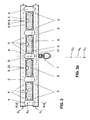
- a cross member 1 comprises a linear, ie a straight, upper flange 2 and a lower flange 3 arranged at a distance therefrom, wherein upper flange 2 and lower flange 3 are connected to a plurality of webs 4.
- the upper flange 2 has a plurality of connecting elements 6 arranged at intervals in the axial direction, for example, in each case designed as a screw connection or carrying bolt.
- Hammerhead bolts are preferably suitable as connecting elements 6 or screw connections.
- the cross member 1 is preferably releasably fixable to a supporting structure 15.
- the upper flange 2 is formed linearly and comprises a plurality of spaced suspension points A, wherein at each suspension points A of the upper belt 2 each have a connecting element 6 is arranged.
- the lower flange 3 in the state without a traffic load F a parallel to the upper flange 2, ie, linear arrangement.
- the lower flange 3 in the state without traffic load F has a convex curvature facing the upper flange 2 and thus has a bias.
- anchor rail 14 Hyfen rail
- the upper flange 2 corresponding openings, such as holes 20 have.
- the individual connecting elements 6 can be arranged at equal distances from one another according to the respectively provided suspension points A over a system length L on the upper belt 2.
- the traverse 1 is made of a steel or an aluminum alloy, is integrally formed and the webs 4 may be arranged at right angles or diagonally between the upper flange 2 and lower flange 3.
- a Traverse 1 can be made of a hollow material (hollow profile) or a solid material.
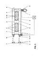
- the axis of upper flange A O and the axis of lower flange A U are arranged in parallel and the axes of the webs A S intersect the axes of upper and lower belt (A O , A U ), as this Fig. 2a shows.
- corresponding free spaces 5 may be provided between upper flange 2 and lower flange 3 and the webs 4.
- a partition plate 9 may be provided between upper flange 2, lower flange 3 and the adjacent webs 4, which is connected to the webs 4 and at least parts of the inner sides 12, 13 of upper flange 2 and lower flange 3 by means of welded constructions.
- the individual suspension points A are preferably provided with the respectively individually assigned connecting elements 6.
- they preferably also have free spaces 5 in the corner regions of web 4 and the inner sides 12, 13 and the region of the connecting elements 6. Fig. 2 ) on. These free spaces 5 ( Fig. 2 ) are necessarily smaller than the free spaces 5 without bulkhead plates 9 (FIG. Fig.1 ).
- each partition plate 9 may have free spaces 5 arranged parallel to the inner sides 12, 13 of upper flange or lower flange 2, 3 ( Fig. 4 ). In the training gem. Fig. 2 For reasons of clarity, only the elastic deformation on the lower flange 3 is shown; the elastic deformation of the webs 4 and the partition plates 9 (when the traffic load is applied) are not shown.
- the initially mentioned convex curvature of the lower belt 3 is preferably a circular arc 8 and this circular arc 8 includes a vertex S, which is arranged centrally with respect to the system length L of the traverse 1.
- the circular arc 8 is preferably delimited by a first end point E 1 and a second end point E 2 , the maximum distance of which corresponds to the system length L of the crossbeam 1.
- a cross member 1 which for an approved traffic load F of max. 500 kg and made of pipe material based on an aluminum alloy, with a system length L of 1000 mm, with a system height H of 250 mm, with a top flange 2, a bottom flange 3 and webs 4 each having an outer diameter of 50 mm and a wall thickness of 5 mm each vertex S of the circular arc 8 of the lower belt 3 a deflection x of max. 5 mm, i. x ⁇ 5 mm, to the horizontal of the lower leg 3 have.
- the cross member 1 has a system height H, bounded by the outer side 10 of the upper belt 2 and the outer side 11 of the lower belt 3, on. Furthermore, the traverse 1 has a certain system length L.
- the system height H and the system length L of trusses 1 can have standardized sizes.
- the Traverse 1 may consist of steel or preferably an aluminum alloy.
- Upper flange 2 and lower flange 3 are connected via the webs 4 by means of a material connection, in particular a welded construction.
- the webs 4 are integrally connected to an inner side 12 of the upper belt 2 and to an inner side 13 of the lower belt 3.
- Upper flange 2 and lower flange 3 and the webs 4 may be formed from a hollow profile with circular or elliptical or polygonal cross-section.
- a breakpoint is provided, which receives a stop means 7.
- the stop means 7 can, as in the Fig. 1 and 2 shown, in the lower flange 3 releasably arranged eyebolt with an O-ring. At this stop means 7 attacks the load F in the load case.
- the traverse 1 is not on a central arrangement of the stop means. 7 limited. Rather, taking into account the permissible traffic load F or traffic loads F, a plurality of stop means 7, preferably symmetrically arranged at intervals, may be provided on the lower belt 3.
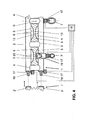
- Fig. 4 shows an example of an off-center arrangement of a stop means 7 '.
- the stop means 7 ' may preferably be a detachable on the lower flange 3 can be arranged clamping device.
- the clamping device may be formed by half clamps 19.
- Such half clamps 19 are formed in two or more parts connected in half-shell shape, the cross-section (round or rectangular / square tube) of lower flange 3 adapted and surround the lower flange 3 and may include an O-ring for striking a traffic load F.
- a load cell 17 may be arranged as a measuring device in the area of each one acting traffic load F. Furthermore, such load cells 17 can be arranged on the clamping devices (half clamps 19). Such a load cell 17 may comprise an optical display or may be signal and / or circuitry coupled to a display and / or evaluation device 18.
- the Traverse 1 can be modular and can with other, identical truss 1 '( Fig. 3 ) strung together by means of coupling elements 16, are releasably connected.
- the coupling elements 16 are preferably arranged at one end on the upper flange 2 and at the associated end of the lower belt 3 of the first cross member 1 and can according to Fig. 3 (Double arrow) end with Obergurt 2 'and lower flange 3' another Traverse 1 'releasably, preferably positively connected.
- the coupling elements 16 by means of connecting means, in particular bolts, detachably connected to the trusses 1,1 '.
- the coupling elements 16 for connecting the end of the modular constructed trusses 1, 1 '- n are not limited to a linear (aligned) connection of two trusses 1,1'.
- further coupling elements 16 may be formed as T-pieces for connecting three trusses 1, 1 ', 1 "or crosspieces for connecting four trusses 1, 1', 1", 1 '", so that the trusses 1 -1" At a right angle to one another or intersecting (traverses 1-1 "') can be arranged
- coupling elements 16 in conjunction with several trusses 1 - n spatial structures, for example, when used in the stage technology, are formed.
- At least one load cell 17 may be provided, which may comprise a visual display or signaling and / or circuitry with the display and / or evaluation device 18th can be coupled.
- a load cell 17 may - as in Fig. 4 shown - outside of the upper flange 2 and be arranged on the lower flange 3.
- a load cell 17, including power supply and transmitter may be disposed within the upper belt 2 and lower belt 3 and / or the coupling elements 16, respectively.
- the Traverse 1 is not limited to the described training with upper flange 2 and lower flange 3. Rather, at least one center belt (not shown) may be provided, which is arranged in a parallel arrangement between the upper belt 2 and lower belt 3. The at least one center belt is in turn by means of Webs 4 connected to the upper flange 2 and the lower flange 3. If necessary, 5 bulkheads 9 can be provided in the open spaces.
- Upper belt 2 and lower belt 3 and the at least one center belt and the webs 4 may be formed from a hollow profile with circular or elliptical or polygonal cross-section.
- the lower belt 3 in the state without traffic load F may also have a parallel arrangement or a convex curvature facing the upper belt 2.
- the axis of upper flange A O and the axis of lower flange A U are in turn aligned, in the case of the parallel arrangement of the lower flange 3 to the upper flange 2, the axes A O , A U are arranged in parallel, and the axes of the webs A S intersect the axes of Upper and lower girth (A O , A U ).
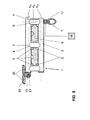
- a traverse 1 has in each case at the free end faces of the upper flange 2 each one, with the upper flange 2 fixedly connected gear mechanism (21, 23, 24, or 21 to 24).
- gear mechanism 21, 23, 24, or 21 to 24
- Such a gear mechanism (21, 23, 24, or 21 to 24) is identical on each end face of the upper flange 2, but executed in mirror image.
- the crossbeam 1 comprises a first, fixedly arranged on the top flange 2 joint 21.
- the first stationary joint 21 is in operative connection with a second, fixedly arranged on a plate 24 at right angles joint 23.
- the two joints 21, 23 are connected by means of a support pin (without reference numerals).
- the crossbeam 1 comprises a first, fixedly arranged on the top flange 2 joint 21.
- the first stationary joint 21 is in operative connection with a coupling rod 22.
- the first stationary joint 21 and the coupling rod 22 by means of a support pin (without reference numerals) are connected.
- the coupling rod 22 is further connected to a second, fixed to the plate 24 at right angles arranged joint 23 in operative connection.
- the coupling rod 22 and the second fixed joints 23 by means of a support pin (without reference numerals) are connected.
- the plate 24 gem. Fig. 5 and 6 is parallel to a structural structure 15, such as a hall or stage ceiling, mountable.
- each plate has 24 holes 20 for receiving connecting elements 6.
- a connecting element 6 is thus provided, which is connected to an anchor rail 14 and Halfenschiene of the supporting structure 15.
- suspension points A are not used, however, because in this case the two frontally arranged on the upper flange 2 gear mechanisms as suspension points A connect to the respective plate 24 or by means of the respective connecting element 6 to the Anker rail 14 or Halfenschiene realize.
- corresponding suspension points A or bores 20 on the top flange 2 can already be omitted during production.
- a respective coupling element 16 can be used as part of a gear mechanism, which is detachably arranged connected to the associated plate 24 on the supporting structure 15 and the anchor rail 14.
- FIG. 6 shows, the transmission mechanism (21, 23, 24, or 21 to 24) on each end face of the upper flange 2 with a load cell 17 already described circuit and signaling technology to be coupled.
- Each load cell 17 is coupled to an already described display / evaluation 18 circuit and signaling technology.
- the upper flange 2 is formed linearly and in each case at the free end faces of the upper flange 2 is one, with the upper flange 2 firmly connected gear mechanism 21, 23, 24; or 21 to 24 is arranged.
- Each gear mechanism 21, 23, 24; or 21 to 24 comprises a plate (24) which is releasably connected by means of connecting elements (6) to a supporting structure (15) or anchor rail 14 (to the supporting structure 15).
- the lower belt 3 has a parallel arrangement or a convex curvature facing the upper belt 2.
- the axis of Obergurt A O and the axis of lower flange A U are arranged in alignment and the axes of the webs A S intersect the axes of upper and lower chord A O , A U.
- this arrangement is also parallel.
- the mode of action acc. Fig. 1 to 4 is as follows.
- the traverse 1 with a linear upper flange 2 and a, adjacent at a distance arranged lower flange 3 and more, the upper flange 2 and the lower flange 3 materially connecting webs 4 comprises the lower flange 3 in the state without traffic load F with a top flange 2 facing parallel arrangement to the top flange 2 or with a convex curvature to the top flange 2.
- the top flange 2 is detachably connected to the suspension points A provided by means of the connecting elements 6 with the structural structure 15, alternatively the arranged on the structural structure 15 anchor rail 14 (Halfen rail).
- a traffic load F can be attached to at least one stopping point (lower chord 3) with stop means 7.
- the lower chord 3 remains substantially parallel, ie linear to the upper chord 2.
- the originally convex, biased curve shape of the lower chord 3 changes as a result of the acting traffic load F and changes into a linear embodiment of the lower chord 3 ,
- the maximum traffic load F for each traverse 1 is set.
- the breakpoint of the stop means 7 is arranged on a straight line, in the present example of the vertical, to the vertex S of the convex curvature.
- the representation of the convex curvature of the lower chord 3 in the Fig. 1 and 2 is merely shown for convenience in this form and thus is not to scale.
- the connecting elements 6 can preferably connect the respective traverse 1 with defined torque with the structural construction 15 or the anchor rail 14. In terms of safety, the respective defined torques can be recorded and documented in terms of data technology.
- Fig. 7 shows such a connecting element 6, which shows by way of example a per se known hammer head screw 30 with threaded bolt 28.
- the associated anchor rail 14 is not shown for reasons of clarity and the hammer head screw 30 is not (yet) shown rotated in the installed position.
- the hammer head screw 30 (with threaded bolt 28) is arranged in the corresponding suspension point A associated bore 20 on the top flange 2 (outer side 10) of the cross member 1 and thus penetrates the upper flange 2.
- the threaded bolt 28 protrudes with its free end on the inner side 12 of the upper flange 2 in the free space 5.
- a first disc 25, a disc-shaped damping material 26 and a second disc 27 are arranged in the axial direction thereof.
- the discs 25, 27 are made of a metallic material, such as steel, and have a bore which is in operative connection with the threaded bolt 28.
- the damping material 26 is preferably made of an elastomer or contains at least one elastomer and also has a bore which is in operative connection with the threaded bolt 28.
- a rubber material or other elastically deformable plastic or mixtures thereof may be used.
- the connecting elements 6 may each be formed with a damping element 25 to 27.
- the damping material 26 in particular may have different moduli of elasticity (modulus of elasticity) for each individual damping element 25 to 27 or the connecting element 6.
- moduli of elasticity modulus of elasticity
- the mode of action acc. Fig. 5 and 6 is as follows.
- the traverse 1 with a linear upper flange 2 and a, adjacent at a distance arranged lower flange 3 and more, the upper flange 2 and the lower flange 3 materially connecting webs 4 comprises the lower flange 3 in the state without traffic load F with a top flange 2 facing parallel arrangement to the top flange 2 or with a convex curvature to the top flange 2.
- the top flange 2 is at each end face with a transmission mechanism 21, 23, 24 or 21 to 24 on the respective associated plate 24 with connecting elements 6 with the supporting structure 15, alternatively at the Structural structure 15 arranged anchor rail 14 (Halfen rail) releasably connected.
- a traffic load F can be attached to at least one stopping point (lower chord 3) with stop means 7.
- the lower chord 3 remains substantially parallel, ie linear to the upper chord 2.
- the originally convex, biased curve shape of the lower chord 3 changes as a result of the acting traffic load F and changes into a linear embodiment of the lower chord 3 ,
- the maximum traffic load F for each traverse 1 is set.
- the breakpoint of the stop means 7 is arranged on a straight line, in the present example of the vertical, to the vertex S of the convex curvature.
- the linear embodiment of the lower belt 3 returns to the convex curve shape (second embodiment).
- the representation of the convex curvature of the lower chord 3 in the Fig. 1 and 2 is merely shown for convenience in this form and thus is not to scale.
- the connecting elements 6 can preferably connect the respective traverse 1 with defined torque with the structural construction 15 or the anchor rail 14. In terms of safety, the respective defined torques can be recorded and documented in terms of data technology.
- the method of operation comprises a method for mounting a crossbeam 1 on a supporting structure 15, alternatively on an anchor rail 14 arranged thereon, the crossbeam 1 being formed by means of a top flange 2 and a bottom flange 3 as well as a plurality of webs 4 connecting the top flange 2 and the bottom flange 3 , in that a plurality of suspension points A are provided at intervals on the top flange 2, that a connecting element 6 is then arranged on the top flange 2 at each suspension point A and that subsequently each connecting element 6 is releasably connected to the structural structure 15 or the anchor rail 14.
- the suspension points A and thus the connecting elements 6 can be provided on the upper flange 2 at equal distances from each other.
- a cross member 1 with another, identical cross member 1 'by means of coupling elements 16 lined up, are releasably connected.
- the cross member 1 ' is analogously connected to the traverse 1 at the suspension points A by means of the connecting elements 6 with the supporting structure 15 or the or an arranged on the supporting structure 15 anchor rail 14.
- At least one anchor rail 14 is fixedly arranged on the supporting structure 15 and the connecting elements 6 of the crossbar 1, 1 'are detachably connected to the anchor rail 14.
- the upper flange 2 at each end, each with a gear mechanism 21, 23, 24 or 21 to 24 on the respective associated plate 24 with connecting elements 6 with the supporting structure 15, alternatively the arranged on the supporting structure 15 anchor rail 14 (Halfen rail) are releasably connected ,
- the end faces on the top flange form the suspension points of the traverse 1 in this embodiment.
- a traffic load F can be attached to at least one stopping point (lower chord 3) with stop means 7.
- the lower chord 3 remains substantially parallel, ie linear to the upper chord 2.
- each suspension point A by means of one, a plate 24 comprehensive gear mechanism 21, 23, 24; or 21 to 24 with connecting elements 6 to the supporting structure 15 or anchor rail 14 releasably connected.
Landscapes
- Engineering & Computer Science (AREA)
- Architecture (AREA)
- Civil Engineering (AREA)
- Structural Engineering (AREA)
- Bridges Or Land Bridges (AREA)
- Flanged Joints, Insulating Joints, And Other Joints (AREA)
- Lining Or Joining Of Plastics Or The Like (AREA)
- Body Structure For Vehicles (AREA)
- Road Signs Or Road Markings (AREA)
- Refuge Islands, Traffic Blockers, Or Guard Fence (AREA)
Applications Claiming Priority (2)
| Application Number | Priority Date | Filing Date | Title |
|---|---|---|---|
| DE102013005275 | 2013-03-26 | ||
| DE201410002666 DE102014002666A1 (de) | 2013-03-26 | 2014-02-28 | Traverse und Verfahren zum Montieren |
Publications (3)
| Publication Number | Publication Date |
|---|---|
| EP2784238A2 true EP2784238A2 (fr) | 2014-10-01 |
| EP2784238A3 EP2784238A3 (fr) | 2015-04-29 |
| EP2784238B1 EP2784238B1 (fr) | 2018-11-21 |
Family
ID=50345848
Family Applications (1)
| Application Number | Title | Priority Date | Filing Date |
|---|---|---|---|
| EP14001028.1A Active EP2784238B1 (fr) | 2013-03-26 | 2014-03-20 | Traverse et procédé de montage |
Country Status (3)
| Country | Link |
|---|---|
| US (1) | US20140290177A1 (fr) |
| EP (1) | EP2784238B1 (fr) |
| DE (1) | DE102014002666A1 (fr) |
Cited By (1)
| Publication number | Priority date | Publication date | Assignee | Title |
|---|---|---|---|---|
| CN110217684A (zh) * | 2019-05-16 | 2019-09-10 | 中交一公局厦门工程有限公司 | 一种箱梁底腹板钢筋吊装工具 |
Families Citing this family (2)
| Publication number | Priority date | Publication date | Assignee | Title |
|---|---|---|---|---|
| DE102017102372B3 (de) * | 2017-02-07 | 2018-05-30 | Stahl Cranesystems Gmbh | Vorrichtung mit einem Träger in Segmentbauweise und Verfahren |
| DE102018008181A1 (de) * | 2018-10-16 | 2020-04-16 | Rainhard Nordbrock | Verfahren und Vorrichtung zur Überwachung einer Lastaufnahmeeinrichtung an einer Tragwerkskonstruktion |
Citations (4)
| Publication number | Priority date | Publication date | Assignee | Title |
|---|---|---|---|---|
| DE292751C (fr) | ||||
| US6571527B1 (en) | 2000-09-20 | 2003-06-03 | Cooper Technologies Company | Elongate structural member comprising a zigzag web and two chords wherein one chord comprises a channel with inwardly directed lips on the channel ends |
| DE10341931A1 (de) | 2003-09-11 | 2005-04-21 | Remmer Briese | Hebetraverse |
| DE102009004073A1 (de) | 2009-01-02 | 2010-07-15 | N&M Gmbh | Montagesystem für Hängepunkte |
Family Cites Families (19)
| Publication number | Priority date | Publication date | Assignee | Title |
|---|---|---|---|---|
| US4120065A (en) * | 1977-12-15 | 1978-10-17 | Eugene W. Sivachenko | Lightweight modular, truss-deck bridge system |
| DE3824938A1 (de) * | 1988-07-22 | 1990-02-01 | Langer Ruth Geb Layher | Podium |
| US4957186A (en) * | 1989-12-11 | 1990-09-18 | T J International, Inc. | Span-adjustable open-web support bracket |
| US5361495A (en) * | 1992-11-05 | 1994-11-08 | Pyle S H | Roof truss fabrication method |
| SE9701931L (sv) * | 1997-05-23 | 1998-11-24 | Gustav Naeslund | Lättbalk i form av en I-balk av tunnplåt |
| NZ516047A (en) * | 1999-06-09 | 2003-08-29 | John Clement Preston | Multi-purpose structural component |
| KR100423757B1 (ko) * | 2001-05-04 | 2004-03-22 | 원대연 | 프리스트레스트 합성 트러스 보 및 그의 제조 방법 |
| HRP20020044B1 (en) * | 2002-01-16 | 2008-11-30 | Mara-Institut D.O.O. | Indirectly prestressed, concrete, roof-ceiling construction with flat soffit |
| GB0304248D0 (en) * | 2003-02-25 | 2003-03-26 | James Lupton Consultants Ltd | Deck structure |
| US7513085B2 (en) * | 2003-10-24 | 2009-04-07 | Nucon Steel Corporation | Metal truss |
| US7448103B2 (en) * | 2004-05-19 | 2008-11-11 | Reynolds Zachary M | Enhanced girder system |
| US20080092481A1 (en) * | 2004-07-21 | 2008-04-24 | Murray Ellen | Building Methods |
| CA2497711A1 (fr) * | 2005-02-18 | 2006-08-18 | Scene Ethique Inc. | Systeme de support structural porteur montable et demontable |
| US20060236644A1 (en) * | 2005-03-31 | 2006-10-26 | Bush Thomas A | Adjustable truss construction |
| US7516585B2 (en) * | 2005-11-21 | 2009-04-14 | Usg Interiors, Inc. | Grid tee for suspension ceiling |
| DE102005000201A1 (de) * | 2005-12-22 | 2007-07-26 | Hilti Ag | Träger für Installationen im Bereich der Haustechnik und der Industrie |
| CN101254846A (zh) * | 2007-03-02 | 2008-09-03 | 中国国际海运集装箱(集团)股份有限公司 | 台架箱底架的制作方法 |
| US8434232B2 (en) * | 2009-06-26 | 2013-05-07 | Weyerhaeuser Nr Company | Method for constructing a truss from selected components |
| US20110239551A1 (en) * | 2010-03-31 | 2011-10-06 | National University Corporation Nagoya Institute Of Technology | Self-centering compact damper unit applicable to structures for seismic energy dissipation |
-
2014
- 2014-02-28 DE DE201410002666 patent/DE102014002666A1/de not_active Withdrawn
- 2014-03-20 EP EP14001028.1A patent/EP2784238B1/fr active Active
- 2014-03-26 US US14/225,635 patent/US20140290177A1/en not_active Abandoned
Patent Citations (4)
| Publication number | Priority date | Publication date | Assignee | Title |
|---|---|---|---|---|
| DE292751C (fr) | ||||
| US6571527B1 (en) | 2000-09-20 | 2003-06-03 | Cooper Technologies Company | Elongate structural member comprising a zigzag web and two chords wherein one chord comprises a channel with inwardly directed lips on the channel ends |
| DE10341931A1 (de) | 2003-09-11 | 2005-04-21 | Remmer Briese | Hebetraverse |
| DE102009004073A1 (de) | 2009-01-02 | 2010-07-15 | N&M Gmbh | Montagesystem für Hängepunkte |
Cited By (1)
| Publication number | Priority date | Publication date | Assignee | Title |
|---|---|---|---|---|
| CN110217684A (zh) * | 2019-05-16 | 2019-09-10 | 中交一公局厦门工程有限公司 | 一种箱梁底腹板钢筋吊装工具 |
Also Published As
| Publication number | Publication date |
|---|---|
| US20140290177A1 (en) | 2014-10-02 |
| EP2784238A3 (fr) | 2015-04-29 |
| DE102014002666A1 (de) | 2014-10-02 |
| EP2784238B1 (fr) | 2018-11-21 |
Similar Documents
| Publication | Publication Date | Title |
|---|---|---|
| DE3224986C2 (de) | Vorrichtung zur Befestigung von Montageteilen an einer Betonwand | |
| EP3931142A2 (fr) | Zone de liaison de section de charpente | |
| DE102013108299B4 (de) | Pressengestell und Verfahren zum Montieren eines Pressengestells sowie Presse mit einem solchen Pressengestell | |
| EP2784238B1 (fr) | Traverse et procédé de montage | |
| EP1034344B1 (fr) | Piece d'accouplement | |
| DE102006011336A1 (de) | Bauelement zur Wärmedämmung | |
| EP2130984B1 (fr) | Corps de répartition de charge doté d'un système de support de profil | |
| DE202007018210U1 (de) | Stahlbetonbauelement mit Queranker | |
| DE202006016481U1 (de) | Trägerverbundsystem | |
| DE102012216957A1 (de) | Ankerschienenanordnung | |
| EP2253779A2 (fr) | Système de coffrage | |
| DE202014001757U1 (de) | Traverse | |
| DE102019133999A1 (de) | Anordnung zum Verbinden eines Bauwerkteils mit einem dem Bauwerkteil vorgelagerten Außenteil | |
| DE3406550A1 (de) | Knotenanschluss eines fachwerkstabes aus rechteckrohr | |
| DE102013208018A1 (de) | Gerüst für die Erstellung baulicher Anlagen | |
| DE102014018781B3 (de) | Kraftmesseinrichtung | |
| DE3786293T2 (de) | Stahl- und bewehrte Betonkonstruktionen, insbesondere zur Trägerherstellung, insbesondere als Dachbalken benutzbarer Träger oder Träger mit grosser Spannweite. | |
| DE4217783A1 (de) | Laststuetzstruktur | |
| EP1697601B1 (fr) | Etrier support destine a la fixation d'elements de fa ade ou equivalent sur les murs exterieurs de batiments | |
| DE202014009970U1 (de) | Kraftmesseinrichtung | |
| CH700568B1 (de) | Zugglied für Bauwerke. | |
| DE19611200A1 (de) | Bewehrungsanordnung für Porenbeton-Bauteile | |
| DE29909395U1 (de) | Vorrichtung zur Eckbefestigung einer Leibungsplatte | |
| EP1288392B1 (fr) | Structure de support pour un système porteur d'une structure d'estrade, de podium, d'échafaudage ou similaire | |
| DE19530572A1 (de) | Gebäude-Tragkonstruktion |
Legal Events
| Date | Code | Title | Description |
|---|---|---|---|
| 17P | Request for examination filed |
Effective date: 20140320 |
|
| AK | Designated contracting states |
Kind code of ref document: A2 Designated state(s): AL AT BE BG CH CY CZ DE DK EE ES FI FR GB GR HR HU IE IS IT LI LT LU LV MC MK MT NL NO PL PT RO RS SE SI SK SM TR |
|
| AX | Request for extension of the european patent |
Extension state: BA ME |
|
| PUAI | Public reference made under article 153(3) epc to a published international application that has entered the european phase |
Free format text: ORIGINAL CODE: 0009012 |
|
| PUAL | Search report despatched |
Free format text: ORIGINAL CODE: 0009013 |
|
| AK | Designated contracting states |
Kind code of ref document: A3 Designated state(s): AL AT BE BG CH CY CZ DE DK EE ES FI FR GB GR HR HU IE IS IT LI LT LU LV MC MK MT NL NO PL PT RO RS SE SI SK SM TR |
|
| AX | Request for extension of the european patent |
Extension state: BA ME |
|
| RIC1 | Information provided on ipc code assigned before grant |
Ipc: E04C 3/08 20060101AFI20150324BHEP |
|
| R17P | Request for examination filed (corrected) |
Effective date: 20150518 |
|
| RBV | Designated contracting states (corrected) |
Designated state(s): AL AT BE BG CH CY CZ DE DK EE ES FI FR GB GR HR HU IE IS IT LI LT LU LV MC MK MT NL NO PL PT RO RS SE SI SK SM TR |
|
| STAA | Information on the status of an ep patent application or granted ep patent |
Free format text: STATUS: EXAMINATION IS IN PROGRESS |
|
| 17Q | First examination report despatched |
Effective date: 20161214 |
|
| GRAP | Despatch of communication of intention to grant a patent |
Free format text: ORIGINAL CODE: EPIDOSNIGR1 |
|
| STAA | Information on the status of an ep patent application or granted ep patent |
Free format text: STATUS: GRANT OF PATENT IS INTENDED |
|
| INTG | Intention to grant announced |
Effective date: 20180912 |
|
| GRAS | Grant fee paid |
Free format text: ORIGINAL CODE: EPIDOSNIGR3 |
|
| GRAA | (expected) grant |
Free format text: ORIGINAL CODE: 0009210 |
|
| STAA | Information on the status of an ep patent application or granted ep patent |
Free format text: STATUS: THE PATENT HAS BEEN GRANTED |
|
| AK | Designated contracting states |
Kind code of ref document: B1 Designated state(s): AL AT BE BG CH CY CZ DE DK EE ES FI FR GB GR HR HU IE IS IT LI LT LU LV MC MK MT NL NO PL PT RO RS SE SI SK SM TR |
|
| REG | Reference to a national code |
Ref country code: CH Ref legal event code: EP |
|
| REG | Reference to a national code |
Ref country code: IE Ref legal event code: FG4D Free format text: LANGUAGE OF EP DOCUMENT: GERMAN |
|
| REG | Reference to a national code |
Ref country code: DE Ref legal event code: R096 Ref document number: 502014010102 Country of ref document: DE |
|
| REG | Reference to a national code |
Ref country code: AT Ref legal event code: REF Ref document number: 1067701 Country of ref document: AT Kind code of ref document: T Effective date: 20181215 |
|
| REG | Reference to a national code |
Ref country code: NL Ref legal event code: MP Effective date: 20181121 |
|
| PG25 | Lapsed in a contracting state [announced via postgrant information from national office to epo] |
Ref country code: LV Free format text: LAPSE BECAUSE OF FAILURE TO SUBMIT A TRANSLATION OF THE DESCRIPTION OR TO PAY THE FEE WITHIN THE PRESCRIBED TIME-LIMIT Effective date: 20181121 Ref country code: HR Free format text: LAPSE BECAUSE OF FAILURE TO SUBMIT A TRANSLATION OF THE DESCRIPTION OR TO PAY THE FEE WITHIN THE PRESCRIBED TIME-LIMIT Effective date: 20181121 Ref country code: NO Free format text: LAPSE BECAUSE OF FAILURE TO SUBMIT A TRANSLATION OF THE DESCRIPTION OR TO PAY THE FEE WITHIN THE PRESCRIBED TIME-LIMIT Effective date: 20190221 Ref country code: BG Free format text: LAPSE BECAUSE OF FAILURE TO SUBMIT A TRANSLATION OF THE DESCRIPTION OR TO PAY THE FEE WITHIN THE PRESCRIBED TIME-LIMIT Effective date: 20190221 Ref country code: LT Free format text: LAPSE BECAUSE OF FAILURE TO SUBMIT A TRANSLATION OF THE DESCRIPTION OR TO PAY THE FEE WITHIN THE PRESCRIBED TIME-LIMIT Effective date: 20181121 Ref country code: ES Free format text: LAPSE BECAUSE OF FAILURE TO SUBMIT A TRANSLATION OF THE DESCRIPTION OR TO PAY THE FEE WITHIN THE PRESCRIBED TIME-LIMIT Effective date: 20181121 Ref country code: IS Free format text: LAPSE BECAUSE OF FAILURE TO SUBMIT A TRANSLATION OF THE DESCRIPTION OR TO PAY THE FEE WITHIN THE PRESCRIBED TIME-LIMIT Effective date: 20190321 Ref country code: FI Free format text: LAPSE BECAUSE OF FAILURE TO SUBMIT A TRANSLATION OF THE DESCRIPTION OR TO PAY THE FEE WITHIN THE PRESCRIBED TIME-LIMIT Effective date: 20181121 |
|
| PG25 | Lapsed in a contracting state [announced via postgrant information from national office to epo] |
Ref country code: GR Free format text: LAPSE BECAUSE OF FAILURE TO SUBMIT A TRANSLATION OF THE DESCRIPTION OR TO PAY THE FEE WITHIN THE PRESCRIBED TIME-LIMIT Effective date: 20190222 Ref country code: SE Free format text: LAPSE BECAUSE OF FAILURE TO SUBMIT A TRANSLATION OF THE DESCRIPTION OR TO PAY THE FEE WITHIN THE PRESCRIBED TIME-LIMIT Effective date: 20181121 Ref country code: RS Free format text: LAPSE BECAUSE OF FAILURE TO SUBMIT A TRANSLATION OF THE DESCRIPTION OR TO PAY THE FEE WITHIN THE PRESCRIBED TIME-LIMIT Effective date: 20181121 Ref country code: PT Free format text: LAPSE BECAUSE OF FAILURE TO SUBMIT A TRANSLATION OF THE DESCRIPTION OR TO PAY THE FEE WITHIN THE PRESCRIBED TIME-LIMIT Effective date: 20190321 Ref country code: AL Free format text: LAPSE BECAUSE OF FAILURE TO SUBMIT A TRANSLATION OF THE DESCRIPTION OR TO PAY THE FEE WITHIN THE PRESCRIBED TIME-LIMIT Effective date: 20181121 Ref country code: NL Free format text: LAPSE BECAUSE OF FAILURE TO SUBMIT A TRANSLATION OF THE DESCRIPTION OR TO PAY THE FEE WITHIN THE PRESCRIBED TIME-LIMIT Effective date: 20181121 |
|
| PG25 | Lapsed in a contracting state [announced via postgrant information from national office to epo] |
Ref country code: DK Free format text: LAPSE BECAUSE OF FAILURE TO SUBMIT A TRANSLATION OF THE DESCRIPTION OR TO PAY THE FEE WITHIN THE PRESCRIBED TIME-LIMIT Effective date: 20181121 Ref country code: PL Free format text: LAPSE BECAUSE OF FAILURE TO SUBMIT A TRANSLATION OF THE DESCRIPTION OR TO PAY THE FEE WITHIN THE PRESCRIBED TIME-LIMIT Effective date: 20181121 Ref country code: CZ Free format text: LAPSE BECAUSE OF FAILURE TO SUBMIT A TRANSLATION OF THE DESCRIPTION OR TO PAY THE FEE WITHIN THE PRESCRIBED TIME-LIMIT Effective date: 20181121 Ref country code: IT Free format text: LAPSE BECAUSE OF FAILURE TO SUBMIT A TRANSLATION OF THE DESCRIPTION OR TO PAY THE FEE WITHIN THE PRESCRIBED TIME-LIMIT Effective date: 20181121 |
|
| REG | Reference to a national code |
Ref country code: DE Ref legal event code: R097 Ref document number: 502014010102 Country of ref document: DE |
|
| PG25 | Lapsed in a contracting state [announced via postgrant information from national office to epo] |
Ref country code: RO Free format text: LAPSE BECAUSE OF FAILURE TO SUBMIT A TRANSLATION OF THE DESCRIPTION OR TO PAY THE FEE WITHIN THE PRESCRIBED TIME-LIMIT Effective date: 20181121 Ref country code: SK Free format text: LAPSE BECAUSE OF FAILURE TO SUBMIT A TRANSLATION OF THE DESCRIPTION OR TO PAY THE FEE WITHIN THE PRESCRIBED TIME-LIMIT Effective date: 20181121 Ref country code: EE Free format text: LAPSE BECAUSE OF FAILURE TO SUBMIT A TRANSLATION OF THE DESCRIPTION OR TO PAY THE FEE WITHIN THE PRESCRIBED TIME-LIMIT Effective date: 20181121 Ref country code: SM Free format text: LAPSE BECAUSE OF FAILURE TO SUBMIT A TRANSLATION OF THE DESCRIPTION OR TO PAY THE FEE WITHIN THE PRESCRIBED TIME-LIMIT Effective date: 20181121 |
|
| PLBE | No opposition filed within time limit |
Free format text: ORIGINAL CODE: 0009261 |
|
| STAA | Information on the status of an ep patent application or granted ep patent |
Free format text: STATUS: NO OPPOSITION FILED WITHIN TIME LIMIT |
|
| 26N | No opposition filed |
Effective date: 20190822 |
|
| PG25 | Lapsed in a contracting state [announced via postgrant information from national office to epo] |
Ref country code: SI Free format text: LAPSE BECAUSE OF FAILURE TO SUBMIT A TRANSLATION OF THE DESCRIPTION OR TO PAY THE FEE WITHIN THE PRESCRIBED TIME-LIMIT Effective date: 20181121 Ref country code: MC Free format text: LAPSE BECAUSE OF FAILURE TO SUBMIT A TRANSLATION OF THE DESCRIPTION OR TO PAY THE FEE WITHIN THE PRESCRIBED TIME-LIMIT Effective date: 20181121 |
|
| PG25 | Lapsed in a contracting state [announced via postgrant information from national office to epo] |
Ref country code: LU Free format text: LAPSE BECAUSE OF NON-PAYMENT OF DUE FEES Effective date: 20190320 |
|
| REG | Reference to a national code |
Ref country code: BE Ref legal event code: MM Effective date: 20190331 |
|
| PG25 | Lapsed in a contracting state [announced via postgrant information from national office to epo] |
Ref country code: IE Free format text: LAPSE BECAUSE OF NON-PAYMENT OF DUE FEES Effective date: 20190320 |
|
| PG25 | Lapsed in a contracting state [announced via postgrant information from national office to epo] |
Ref country code: BE Free format text: LAPSE BECAUSE OF NON-PAYMENT OF DUE FEES Effective date: 20190331 |
|
| PG25 | Lapsed in a contracting state [announced via postgrant information from national office to epo] |
Ref country code: TR Free format text: LAPSE BECAUSE OF FAILURE TO SUBMIT A TRANSLATION OF THE DESCRIPTION OR TO PAY THE FEE WITHIN THE PRESCRIBED TIME-LIMIT Effective date: 20181121 |
|
| PG25 | Lapsed in a contracting state [announced via postgrant information from national office to epo] |
Ref country code: MT Free format text: LAPSE BECAUSE OF FAILURE TO SUBMIT A TRANSLATION OF THE DESCRIPTION OR TO PAY THE FEE WITHIN THE PRESCRIBED TIME-LIMIT Effective date: 20181121 |
|
| PG25 | Lapsed in a contracting state [announced via postgrant information from national office to epo] |
Ref country code: CY Free format text: LAPSE BECAUSE OF FAILURE TO SUBMIT A TRANSLATION OF THE DESCRIPTION OR TO PAY THE FEE WITHIN THE PRESCRIBED TIME-LIMIT Effective date: 20181121 |
|
| PG25 | Lapsed in a contracting state [announced via postgrant information from national office to epo] |
Ref country code: HU Free format text: LAPSE BECAUSE OF FAILURE TO SUBMIT A TRANSLATION OF THE DESCRIPTION OR TO PAY THE FEE WITHIN THE PRESCRIBED TIME-LIMIT; INVALID AB INITIO Effective date: 20140320 |
|
| PG25 | Lapsed in a contracting state [announced via postgrant information from national office to epo] |
Ref country code: MK Free format text: LAPSE BECAUSE OF FAILURE TO SUBMIT A TRANSLATION OF THE DESCRIPTION OR TO PAY THE FEE WITHIN THE PRESCRIBED TIME-LIMIT Effective date: 20181121 |
|
| P01 | Opt-out of the competence of the unified patent court (upc) registered |
Effective date: 20230913 |
|
| PGFP | Annual fee paid to national office [announced via postgrant information from national office to epo] |
Ref country code: FR Payment date: 20250325 Year of fee payment: 12 |
|
| PGFP | Annual fee paid to national office [announced via postgrant information from national office to epo] |
Ref country code: GB Payment date: 20250321 Year of fee payment: 12 |
|
| PGFP | Annual fee paid to national office [announced via postgrant information from national office to epo] |
Ref country code: CH Payment date: 20250401 Year of fee payment: 12 |
|
| REG | Reference to a national code |
Ref country code: CH Ref legal event code: U11 Free format text: ST27 STATUS EVENT CODE: U-0-0-U10-U11 (AS PROVIDED BY THE NATIONAL OFFICE) Effective date: 20260401 |
|
| PGFP | Annual fee paid to national office [announced via postgrant information from national office to epo] |
Ref country code: DE Payment date: 20260326 Year of fee payment: 13 |
|
| PGFP | Annual fee paid to national office [announced via postgrant information from national office to epo] |
Ref country code: AT Payment date: 20260320 Year of fee payment: 13 |