EP2784240A2 - Système de fenêtre de toit comprenant une fenêtre de toit et un ensemble de ventilation et procédé de fonctionnement de l'ensemble de ventilation dans la fenêtre de toit - Google Patents
Système de fenêtre de toit comprenant une fenêtre de toit et un ensemble de ventilation et procédé de fonctionnement de l'ensemble de ventilation dans la fenêtre de toit Download PDFInfo
- Publication number
- EP2784240A2 EP2784240A2 EP14159238.6A EP14159238A EP2784240A2 EP 2784240 A2 EP2784240 A2 EP 2784240A2 EP 14159238 A EP14159238 A EP 14159238A EP 2784240 A2 EP2784240 A2 EP 2784240A2
- Authority
- EP
- European Patent Office
- Prior art keywords
- ventilation
- roof window
- predefined
- housing
- assembly
- Prior art date
- Legal status (The legal status is an assumption and is not a legal conclusion. Google has not performed a legal analysis and makes no representation as to the accuracy of the status listed.)
- Granted
Links
Images


Classifications
-
- E—FIXED CONSTRUCTIONS
- E04—BUILDING
- E04D—ROOF COVERINGS; SKY-LIGHTS; GUTTERS; ROOF-WORKING TOOLS
- E04D13/00—Special arrangements or devices in connection with roof coverings; Protection against birds; Roof drainage ; Sky-lights
- E04D13/03—Sky-lights; Domes; Ventilating sky-lights
- E04D13/0325—Sky-lights; Domes; Ventilating sky-lights provided with ventilating means
-
- E—FIXED CONSTRUCTIONS
- E06—DOORS, WINDOWS, SHUTTERS, OR ROLLER BLINDS IN GENERAL; LADDERS
- E06B—FIXED OR MOVABLE CLOSURES FOR OPENINGS IN BUILDINGS, VEHICLES, FENCES OR LIKE ENCLOSURES IN GENERAL, e.g. DOORS, WINDOWS, BLINDS, GATES
- E06B7/00—Special arrangements or measures in connection with doors or windows
- E06B7/02—Special arrangements or measures in connection with doors or windows for providing ventilation, e.g. through double windows; Arrangement of ventilation roses
-
- F—MECHANICAL ENGINEERING; LIGHTING; HEATING; WEAPONS; BLASTING
- F24—HEATING; RANGES; VENTILATING
- F24F—AIR-CONDITIONING; AIR-HUMIDIFICATION; VENTILATION; USE OF AIR CURRENTS FOR SCREENING
- F24F13/00—Details common to, or for air-conditioning, air-humidification, ventilation or use of air currents for screening
- F24F13/08—Air-flow control members, e.g. louvres, grilles, flaps or guide plates
- F24F13/18—Air-flow control members, e.g. louvres, grilles, flaps or guide plates specially adapted for insertion in flat panels, e.g. in door or window-pane
-
- E—FIXED CONSTRUCTIONS
- E06—DOORS, WINDOWS, SHUTTERS, OR ROLLER BLINDS IN GENERAL; LADDERS
- E06B—FIXED OR MOVABLE CLOSURES FOR OPENINGS IN BUILDINGS, VEHICLES, FENCES OR LIKE ENCLOSURES IN GENERAL, e.g. DOORS, WINDOWS, BLINDS, GATES
- E06B7/00—Special arrangements or measures in connection with doors or windows
- E06B7/02—Special arrangements or measures in connection with doors or windows for providing ventilation, e.g. through double windows; Arrangement of ventilation roses
- E06B2007/023—Air flow induced by fan
-
- F—MECHANICAL ENGINEERING; LIGHTING; HEATING; WEAPONS; BLASTING
- F24—HEATING; RANGES; VENTILATING
- F24F—AIR-CONDITIONING; AIR-HUMIDIFICATION; VENTILATION; USE OF AIR CURRENTS FOR SCREENING
- F24F11/00—Control or safety arrangements
- F24F11/0001—Control or safety arrangements for ventilation
- F24F2011/0002—Control or safety arrangements for ventilation for admittance of outside air
Definitions
- the present invention relates to a roof window system comprising a roof window having at least one frame defining a frame plane and including a pane, the roof window further comprising a ventilation device connected to a frame member and adapted for providing ventilation of a building in which the roof window is mounted, and a ventilation assembly for a roof window having a ventilation device, comprising at least one ventilation unit including a at least one ventilator, the at least one ventilation unit being adapted to be connected to the ventilation device of the roof window.
- the invention furthermore relates to a method of operating the ventilation assembly in the roof window.
- One of the primary functions in a window is to allow stale, warm, or otherwise used or spent air inside the building to exit and allowing fresh air from the exterior to enter the building in which the window is installed. This presupposes that the window is openable.
- the provision of ventilation in windows also in situations in which the window is not open, either because it is a fixed window, or simply is not open, has become more or less standard equipment. This is the result of, among other things, increased focus on improving indoor climatic conditions and the microclimate in buildings.
- a roof window providing a ventilating aperture is the well-known VELUX® with a ventilation flap, which in pivot-hung windows also fulfils the double function of operating the window.
- the ventilation flap thus has three positions, viz. a first and closed position, in which the window is closed and no ventilation is provided, a second position, in which the ventilation flap allows passage of air to and from the building, and a third position, in which the window may be operated.
- Other examples of ventilation devices are shown in for instance DK176947B1 .
- Natural ventilation provided by such a ventilation device has a number of advantages. Among others, it is free of charge and noise-less. However, in certain fields of applications, for instance mechanical ventilation may be desirable.
- roof windows and ventilation assemblies provide well-functioning solutions, they also require that the roof window is built to receive such a ventilation assembly, typically by designing special parts and/or requiring further investment in the installation of auxiliary parts and installation equipment. Thus, severe limitations as to retro-fitting existing windows exist.
- each ventilation unit includes a set of flow channels and a set of transition channels having a first connecting end connected, in a mounted condition, to the set of flow channels and a second connecting end connected, in the mounted condition, to the ventilation device of the roof window.
- a method of operating the ventilation assembly is provided.
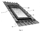
- the roof window system comprises a roof window 1 and a ventilation assembly generally designated 100.
- the roof window 1 comprises at least one frame, in the embodiment shown and described two frames, of which one frame 2 is a stationary frame and an openable sash 3 encasing a pane 4.
- the frame 2 is, in a manner known per se, substantially rectangular and has a top member, and further a bottom member and two side members, not shown in detail, and the sash 3 has a top member, and further a bottom member and two side members, not shown in detail.
- the frame 2 is adapted to be built into a roof structure of virtually any kind, typically comprising a number of rafters and battens, and further non-shown details such as vapour barrier collars etc., below a roofing material 10, here in the form of tiles.
- the window is centre-hung in that the sash 3 is connected to the frame 2 by a pivot hinge (not shown) provided between side members of the frame 2 and sash 3, respectively, to be openable by tilting the sash 3 of the window 1 about a pivot hinge axis defined by the pivot hinge.
- the pivot hinge comprises two parts, namely a sash part and a frame part.
- the hinges used are preferably of the type described in the applicant's earlier patent applications WO9928581 and GB1028251 , where a curved member and a tap on one hinge part travels in a curved guide track in the other during opening and closing of the window.
- the radius of curvature en-tails that when using such hinges, the hinge axis lies at a small distance above the actual hinge parts and as the sash frame is turned first the curved member and then the tap comes out of the track. In combination this provides a pattern of movement which allows easy operation of a centre-hung window and allows the sash frame to be turned substantially entirely around.
- a closed position of the roof window 1 means a position in which the frame plane and the sash plane coincide, that is form an angle of 0 degrees with each other.
- an open position of the roof window 1 as used herein generally means a position in which the sash 3 is tilted about the pivot hinge axis such that the frame plane and the sash plane no longer coincide.
- the window according to the invention may in other embodiments be top-hung, with or without an intermediate frame structure, have the hinge axis somewhere between the top and the centre, be side-hung or for that matter even be bottom-hung, or fixed, i.e. not openable.
- the sash 3 and frame 2 of the window according to the invention may be made of wooden members or members made of cast or extruded polyurethane (PUR).
- PUR polyurethane
- a cladding is generally designated 50, a bottom flashing member 60 and a top flashing member 70 (cf. Fig. 14 ).
- a suitable finishing may be provided, for instance comprising a lining 80.
- the roof window 1 has a ventilation device, which in the embodiment shown comprises a ventilation flap 40, which is connected to the top member of the sash 3 via a hinge connection 41 and which furthermore comprises a handle 42.
- the ventilation flap 40 is an elongate element, which is connected to the top sash member by means of the hinge connection 41 and furthermore to a lock not shown by means of another hinge connection adapted to enable the ventilation flap 40 to be placed in at least two, and preferably at least three, different positions including a closed and at least one open position.
- the lock may for instance be a spring biased locking mechanism.
- Two locks may be provided, or only one lock or for that matter more than two locks may also be provided.
- a top sash module may be provided in the sash top member.
- the handle 42 rotates the ventilation flap 40 from an open position to a closed position and vice versa.
- One or more intermediate positions, in which the ventilation flap 40 may be temporarily locked, may be defined between the open and closed position.
- the sash 3 is pivotally connected to the frame 2, and the ventilation flap 40 is adapted to assume three position, viz. a first or closed position, in which the roof window 1 is closed and no ventilation is provided, a second and ventilating position, in which the roof window 1 is still closed but a ventilation aperture is provided to allow air passage, and a third and entirely open position, in which the sash 3 is able to pivot relative to the frame 2 to open the window.
- Activation of the ventilation assembly 100 thus takes place simply by operating the handle 42 of the ventilation flap 40, which in the embodiment shown forms part of a ventilation device of the window 1.
- the ventilation flap 40 may be able to assume only two position, viz. a closed position and an open, ventilating position, whereas operation of the sash takes place in other ways, for instance by a handle or other operating means located at the bottom member of the sash.
- the roof window 1 of the invention forms part of a roof window system, which in addition to the roof window 1 comprises a ventilation assembly generally designated 100.
- the ventilation assembly 100 is positioned substantially in the plane of the frame 2 and the sash 3 of the roof window 1, above the top member of the window frame 2 as seen in the inclination of the roof.
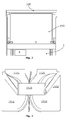
- the ventilation assembly 100 comprises a housing 150 having predefined dimensions and accommodating two ventilation units 110, 120.
- Each ventilation unit includes a set of flow channels 1511, 1512, 1521, 1522 and a set of transition channels 1611 (only shown in respect of one element) having a first connecting end for connection to the set of flow channels and a second connecting end adapted to be connected to the ventilation device of the roof window.
- the ventilation assembly 100 comprises a housing 150 having predefined dimensions, namely a predefined width, a predefined length and predefined height.
- the housing 150 is divided in the height direction into a bottom part 1501 and a top part 1502. In the length direction, the housing 150 is divided into a left-hand part and a right-hand part, which in the embodiment shown are integral with each other.
- Each of the left-hand and right-hand parts accommodates a respective ventilation unit 110 and 120.
- each ventilation unit 110 and 120 has a respective ventilator 130, 140, which in turn is provided with a power supply and activation means (not shown).
- the predefined dimensions of the housing 150 including the predefined width, length and height, are chosen such that the width does not exceed or at most corresponds to the width of the window, and the height does not exceed or at most corresponds to the height of the window.
- the housing 150 of the ventilation assembly 100 is located substantially in the plane of the frame and sash. This makes it possible to provide a ventilation assembly which is inconspicuous and easy to install, as the same aperture in the roof may be utilised, for instance simply by removing one or more rows of tile above the window. No penetration of the underlying vapour barrier collar is necessary, just as the provision of cover members is made easy.
- flashing members fitting the roof window 1 may be provided, just with an extra length as compared to the flashing fitting the window itself to accommodate the ventilation assembly 100 as well.
- the top flashing member 70 may simply be transferred and reused from the top of the roof window 1 to the top of the ventilation assembly 100.
- the top casing of the roof window 1 is simply removed and replaced by the lower-most portion of a cover part of the ventilation assembly 100, or be provided with extension pieces to be coupled to the cover members of the frame. The provision of such cover parts is evident to a person skilled in the art.
- the set of flow channels 1511, 1512, 1521, 1522 is formed by channel parts in the respective bottom and top parts 1501, 1502.
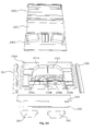
- a recess 1510 (cf. Fig. 3 , showing the recess 1510 in the top part 1502) is formed in the housing 150 to accommodate the ventilation units 110, 120.
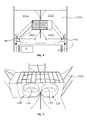
- flow channels 1511, 1521 of the set of flow channels are adapted to be connected to a set of transition channels 1611, respectively, having a first connecting end for connection to the set of flow channels and a second connecting end adapted to be connected to the ventilation device of the roof window.
- the sets of transition channels 1611 are formed in a respective transition element 161, 162, which in the embodiment shown is provided as a separate element from the remaining parts of the ventilation assembly 100, which provides for a particularly easy installation.
- the transition elements 161, 162 may for instance be made from a plastic material or other insulating material to avoid the formation of cold bridges.
- the set of transition channels 1611 in one transition element 161 comprises three apertures at the first connecting end for connection to the set of flow channels 1511, and two apertures at the second connecting end adapted to be connected to the ventilation device 40 of the roof window 1.
- the apertures at the second connecting end are provided with inclined or arched plates 1612.
- the presence of three apertures at the first connecting end in the embodiment shown allows for accommodation of parts of the window, such as the lock case (typically in the case of wide windows having two lock cases) or positioning means in the form of barrel bolts.
- the ventilation takes place via openings in the frame 2 of the roof window 1.
- the ventilation assembly 100 comprises two ventilation units 110, 120, and each ventilation unit comprises a heat exchange device in the form of a regenerator.
- each ventilation unit comprises a heat exchange device in the form of a regenerator.
- each ventilator 130, 140 is pivotally journalled in the ventilation unit 110, 120 to switch the flow direction in the respective set of flow channels 1511, 1512 and 1521, 1522.
- the switch entails that the pressure inside the room is kept substantially constant, without creating either an overpressure or an underpressure.
- the switch in the flow direction of the respective ventilators may be controlled in such a way that the ventilators blow in opposite directions, but it is also conceivable to let the ventilators blow in the same direction to increase the flow. A cycle of 30 seconds in each direction is typical, but other intervals may apply. The control may also be performed manually.
- the ventilation assembly 100 may be operated to perform the desired ventilation. This is carried out substantially by the following steps:
- the step of activating the ventilation assembly is carried out by bringing the ventilation flap 40 from a first to a second position, and de-activated by bringing the ventilation flap 40 from the second to the first position.
- the ventilation flap 40 Preferably from the second to the first or to a third position, in case the roof window 1 is a centre-hung or pivot window, of which the ventilation flap 40 also fulfils the function of an operator.
- the ventilation assembly comprises two ventilation units, and wherein each ventilation unit comprises a heat exchange device, preferably a regenerator, and the ventilator is pivotally journalled in the ventilation unit, the flow direction in the set of flow channels is switched by pivoting the ventilator.
- a set-up with a two-part ventilator is also conceivable.
- the journaling of the ventilator or ventilators has the supplemental advantage that the not-shown cylinder of the ventilator(s) acts as a damper, thus allowing to close-off the ventilation aperture.
- the power supply may be provided as 230 V household supply or in other ways.
- the ventilators 130, 140 are advantageously chosen to provide a flow rate in the range of 10 to 30 m 3 /h to provide air for a room with a volume of 20 to 60 m 3 .
- Test results on commercially available ventilators having such a capacity typically have a sound pressure level (Lpa) of 32 to 42 dB.
- the heat exchange in the regenerators shown in Figs 15 and 16 indicate one situation in Fig. 15 :
- the flow of outgoing warm air in one ventilation unit 110 which heats the regenerator of that ventilation unit such that cooled air exits the ventilation unit 110.
- cool air from the outside passes through the regenerator of ventilation unit 120 and is heated and enters the interior as warm air. This provides for a heat recovery rate of up to 90%.
- Fig. 16 the flow direction has been switched, and cool air entering the now heated regenerator of ventilation unit 110 is heated and enters the interior as warm air, whereas warm air from the interior passes through the regenerator of ventilation unit 120 and is cooled down during the passage and exits to the exterior as cool air.
- the ventilation assembly 100 may furthermore comprise a Hall element for registering the position of the ventilation flap. This provides for the possibility of obtaining operation without physical contact of the parts involved.
- a Hall element is connected to the striking plate. This provides for easy mounting of the ventilation assembly.
- the necessary wiring to power and control the ventilation assembly is guided through well-established parts of the window. No penetration of the underroof is necessary.
- Other elements may be present for indicating a light or other marking in the transition channels, for instance blue for cold air and red for warm air, or the like.
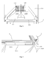
- the ventilation assembly 200 thus has a housing generally designated 250.
- Elements shown in Fig. 17 include an adapting element 260 and two transition elements 261, 262.
- Visible in Fig. 18 are cover parts 251, 252 and 253.
- the housing 250 may have predefined dimensions including a predefined width, a predefined length and a predefined height.
- the housing 250 is divided in the height direction into a top part 2501 seen at the top of these Figures, and a bottom part 2504.
- the top part 2501 has a slightly curved configuration.
- the housing 250 is additionally also divided in the height direction into an intermediate part 2503, and a lid part 2502.
- the lid part 2502 may for instance be made from an insulating material.
- the set of flow channels 2511, 2521 is formed in the bottom part 2504, which also provides a portion serving as transition channel 2611.
- a set of regenerators 270 and 280 is mounted to the intermediate part 2503.
- the ventilation assembly is, as in the previous embodiment, symmetric about a longitudinal line, but other configurations are conceivable.
- the ventilators 230a, 230b, 240a, 240b are included in a ventilator module, which may for instance be formed as a commercially available module such as from InVentilate. Two ventilators 230a, 230b and 240a, 240b, respectively, are thus present in each flow channel 2511 and 2521, respectively.
- the air intake may be provided either at the top of the housing of the ventilation assembly 200, or at the sides thereof.
- the ventilation device comprises a pushbutton ventilation device as disclosed in DK176947B1 .
- the activation and deactivation of the ventilation assembly could also be built-into the ventilation device also in this embodiment.
- the ventilation flap may be electrically or pneumatically operated, possibly controlled by remote control means.
Landscapes
- Engineering & Computer Science (AREA)
- Civil Engineering (AREA)
- Structural Engineering (AREA)
- Architecture (AREA)
- Chemical & Material Sciences (AREA)
- Combustion & Propulsion (AREA)
- Mechanical Engineering (AREA)
- General Engineering & Computer Science (AREA)
- Specific Sealing Or Ventilating Devices For Doors And Windows (AREA)
- Building Environments (AREA)
Priority Applications (1)
| Application Number | Priority Date | Filing Date | Title |
|---|---|---|---|
| PL14159238T PL2784240T3 (pl) | 2013-03-12 | 2014-03-12 | System okien dachowych zawierający okno dachowe i układ wentylacyjny oraz sposób operowania układem wentylacyjnym w oknie dachowym |
Applications Claiming Priority (1)
| Application Number | Priority Date | Filing Date | Title |
|---|---|---|---|
| DKPA201370147A DK179084B1 (en) | 2013-03-12 | 2013-03-12 | A roof window system comprising a ventilation assembly and method of operating such a ventilation assembly |
Publications (3)
| Publication Number | Publication Date |
|---|---|
| EP2784240A2 true EP2784240A2 (fr) | 2014-10-01 |
| EP2784240A3 EP2784240A3 (fr) | 2016-10-26 |
| EP2784240B1 EP2784240B1 (fr) | 2019-04-24 |
Family
ID=50276982
Family Applications (1)
| Application Number | Title | Priority Date | Filing Date |
|---|---|---|---|
| EP14159238.6A Active EP2784240B1 (fr) | 2013-03-12 | 2014-03-12 | Système de fenêtre de toit comprenant une fenêtre de toit et un ensemble de ventilation et procédé de fonctionnement de l'ensemble de ventilation dans la fenêtre de toit |
Country Status (4)
| Country | Link |
|---|---|
| EP (1) | EP2784240B1 (fr) |
| DK (2) | DK179084B1 (fr) |
| ES (1) | ES2730625T3 (fr) |
| PL (1) | PL2784240T3 (fr) |
Cited By (7)
| Publication number | Priority date | Publication date | Assignee | Title |
|---|---|---|---|---|
| DE202016100906U1 (de) | 2016-02-19 | 2016-07-05 | Vkr Holding A/S | Dachfenstersystem mit einem Dachfenster und einem Belüftungsaufbau |
| DK201670807A1 (en) * | 2016-10-14 | 2018-05-07 | Vkr Holding As | A roof window system comprising a ventilation assembly with an exhaust device |
| EP3348736A1 (fr) * | 2017-01-12 | 2018-07-18 | VKR Holding A/S | Système de fenêtre de toit avec ensemble de ventilation présentant un trajet d'écoulement amélioré et procédé de fonctionnement de l'ensemble de ventilation |
| WO2019015732A1 (fr) * | 2017-07-21 | 2019-01-24 | Vkr Holding A/S | Système de fenêtre de toit comprenant des moyens de transition améliorés entre une fenêtre de toit et un ensemble de ventilation |
| CN111547093A (zh) * | 2020-06-03 | 2020-08-18 | 中车(天津)轨道交通设备有限公司 | 一种通风装置 |
| EP3845719A1 (fr) | 2019-12-30 | 2021-07-07 | VKR Holding A/S | Système de fenêtre de toit comprenant une unité de ventilation montée à côté de la fenêtre de toit, structure de toit comprenant un système de fenêtre de toit, procédé de fourniture d'un système de fenêtre de toit et procédé de modernisation d'un système de fenêtre de toit |
| EP3845718A1 (fr) | 2019-12-30 | 2021-07-07 | VKR Holding A/S | Système de fenêtre de toit comprenant une unité de ventilation montée à côté de la fenêtre de toit et procédé de fourniture de ventilation à un bâtiment |
Citations (11)
| Publication number | Priority date | Publication date | Assignee | Title |
|---|---|---|---|---|
| GB1028251A (en) | 1963-01-31 | 1966-05-04 | Villum Benedikt Kann Rasmussen | Improvements in and relating to a hinge mounting for pivotal and tiltable windows |
| EP0372597B1 (fr) | 1988-11-11 | 1992-07-22 | V. Kann Rasmussen Industri A/S | Lucarne de ventilation |
| EP0458725B1 (fr) | 1990-05-23 | 1994-06-29 | V. Kann Rasmussen Industri A/S | Fenêtre avec ventilation mécanique |
| WO1999028581A1 (fr) | 1997-11-11 | 1999-06-10 | Velux Industri A/S | Charniere pour fenetre pivotante |
| DE19811469A1 (de) | 1998-03-17 | 1999-09-30 | Rehfus Bernd | Apparat zur Be- und Entlüftung von Räumen mit einem regenerativen Wärmetauscher |
| DK200001472A (da) | 2000-10-04 | 2002-04-05 | Vkr Holding As | Vindue med ventilationsåbninger |
| DE202004020630U1 (de) | 2004-08-03 | 2006-01-26 | Boden, Christian | Dachfensterintegriertes Solar-Lüftungssystem |
| DE102004037563A1 (de) | 2004-08-03 | 2006-03-16 | Christian Boden | Dachfensterintegriertes Solar-Lüftungssystem |
| DK176947B1 (da) | 2007-12-03 | 2010-06-21 | Form & Plast As | Friskluftventil |
| WO2012025122A1 (fr) | 2010-08-23 | 2012-03-01 | Inventilate Aps | Procédé pour commander un système de ventilation pour la ventilation d'une enceinte, et système de ventilation |
| WO2012155913A1 (fr) | 2011-05-13 | 2012-11-22 | Inventilate Holding Aps | Système de ventilation comportant un générateur rotatif d'écoulement d'air et un ou plusieurs registre(s) mobile(s), et procédé de ventilation utilisant ce système de ventilation |
Family Cites Families (6)
| Publication number | Priority date | Publication date | Assignee | Title |
|---|---|---|---|---|
| US3085490A (en) * | 1960-01-22 | 1963-04-16 | Jenn Air Products Company Inc | Combined skylight and ventilator |
| DE3208392A1 (de) * | 1982-03-09 | 1983-09-22 | Ziehl-Abegg GmbH & Co KG, 7119 Künzelsau | Lueftungsgeraet zum be- und entlueften von raeumen |
| DE8417444U1 (de) * | 1984-06-08 | 1986-12-04 | Wetzel, Alfred, Dipl.-Ing., 5300 Bonn | Gerät zum Anbau an Fenster und Türen zur Verbesserung der Klimawerte in Aufenthaltsräumen |
| ATE59457T1 (de) * | 1985-05-28 | 1991-01-15 | Siegenia Frank Kg | Lueftungsgeraet, insbesondere fuer die luftzufuhr in raeume. |
| GB9607604D0 (en) * | 1996-04-12 | 1996-06-12 | Baker Mark | Ventilation fans |
| IT1397988B1 (it) * | 2010-02-10 | 2013-02-04 | Savio Spa | Dispositivo di scambio d'aria per edifici |
-
2013
- 2013-03-12 DK DKPA201370147A patent/DK179084B1/en not_active IP Right Cessation
-
2014
- 2014-03-12 PL PL14159238T patent/PL2784240T3/pl unknown
- 2014-03-12 ES ES14159238T patent/ES2730625T3/es active Active
- 2014-03-12 EP EP14159238.6A patent/EP2784240B1/fr active Active
- 2014-03-12 DK DK14159238.6T patent/DK2784240T3/da active
Patent Citations (11)
| Publication number | Priority date | Publication date | Assignee | Title |
|---|---|---|---|---|
| GB1028251A (en) | 1963-01-31 | 1966-05-04 | Villum Benedikt Kann Rasmussen | Improvements in and relating to a hinge mounting for pivotal and tiltable windows |
| EP0372597B1 (fr) | 1988-11-11 | 1992-07-22 | V. Kann Rasmussen Industri A/S | Lucarne de ventilation |
| EP0458725B1 (fr) | 1990-05-23 | 1994-06-29 | V. Kann Rasmussen Industri A/S | Fenêtre avec ventilation mécanique |
| WO1999028581A1 (fr) | 1997-11-11 | 1999-06-10 | Velux Industri A/S | Charniere pour fenetre pivotante |
| DE19811469A1 (de) | 1998-03-17 | 1999-09-30 | Rehfus Bernd | Apparat zur Be- und Entlüftung von Räumen mit einem regenerativen Wärmetauscher |
| DK200001472A (da) | 2000-10-04 | 2002-04-05 | Vkr Holding As | Vindue med ventilationsåbninger |
| DE202004020630U1 (de) | 2004-08-03 | 2006-01-26 | Boden, Christian | Dachfensterintegriertes Solar-Lüftungssystem |
| DE102004037563A1 (de) | 2004-08-03 | 2006-03-16 | Christian Boden | Dachfensterintegriertes Solar-Lüftungssystem |
| DK176947B1 (da) | 2007-12-03 | 2010-06-21 | Form & Plast As | Friskluftventil |
| WO2012025122A1 (fr) | 2010-08-23 | 2012-03-01 | Inventilate Aps | Procédé pour commander un système de ventilation pour la ventilation d'une enceinte, et système de ventilation |
| WO2012155913A1 (fr) | 2011-05-13 | 2012-11-22 | Inventilate Holding Aps | Système de ventilation comportant un générateur rotatif d'écoulement d'air et un ou plusieurs registre(s) mobile(s), et procédé de ventilation utilisant ce système de ventilation |
Cited By (14)
| Publication number | Priority date | Publication date | Assignee | Title |
|---|---|---|---|---|
| DE202016100906U1 (de) | 2016-02-19 | 2016-07-05 | Vkr Holding A/S | Dachfenstersystem mit einem Dachfenster und einem Belüftungsaufbau |
| DK201670807A1 (en) * | 2016-10-14 | 2018-05-07 | Vkr Holding As | A roof window system comprising a ventilation assembly with an exhaust device |
| EP3348736A1 (fr) * | 2017-01-12 | 2018-07-18 | VKR Holding A/S | Système de fenêtre de toit avec ensemble de ventilation présentant un trajet d'écoulement amélioré et procédé de fonctionnement de l'ensemble de ventilation |
| US11242686B2 (en) | 2017-07-21 | 2022-02-08 | Vkr Holding A/S | Roof window system with improved transition means between a roof window and a ventilation assembly |
| EP3901404A1 (fr) | 2017-07-21 | 2021-10-27 | VKR Holding A/S | Système de fenêtre de toit comprenant un ensemble de ventilation et utilisation du système de fenêtre de toit en tant que système de transfert de chaleur décentralisé |
| WO2019015732A1 (fr) * | 2017-07-21 | 2019-01-24 | Vkr Holding A/S | Système de fenêtre de toit comprenant des moyens de transition améliorés entre une fenêtre de toit et un ensemble de ventilation |
| DE202018006681U1 (de) | 2017-07-21 | 2022-05-05 | Vkr Holding A/S | Dachfenstersystem mit einer Lüftungsanordnung und Verwendung des Dachfenstersystems als dezentralisiertes Wärmeübertragungssystem |
| EP3845719A1 (fr) | 2019-12-30 | 2021-07-07 | VKR Holding A/S | Système de fenêtre de toit comprenant une unité de ventilation montée à côté de la fenêtre de toit, structure de toit comprenant un système de fenêtre de toit, procédé de fourniture d'un système de fenêtre de toit et procédé de modernisation d'un système de fenêtre de toit |
| EP3845718A1 (fr) | 2019-12-30 | 2021-07-07 | VKR Holding A/S | Système de fenêtre de toit comprenant une unité de ventilation montée à côté de la fenêtre de toit et procédé de fourniture de ventilation à un bâtiment |
| CN113123538A (zh) * | 2019-12-30 | 2021-07-16 | Vkr控股公司 | 具有邻近于屋顶窗户安装的通风单元的屋顶窗户系统、以及为建筑物提供通风的方法 |
| US11686096B2 (en) | 2019-12-30 | 2023-06-27 | Vkr Holding A/S | Roof window system with a ventilation unit mounted adjacent to the roof window, a roof structure including a roof window system, a method of providing a roof window system and a method of retrofitting a roof window system |
| US11834832B2 (en) | 2019-12-30 | 2023-12-05 | Vkr Holding A/S | Roof window system with a ventilation unit mounted adjacent to the roof window, and a method of providing ventilation for a building |
| US11993934B2 (en) | 2019-12-30 | 2024-05-28 | Vkr Holding A/S | Roof window system with a ventilation unit mounted adjacent to the roof window, a roof structure including a roof window system, a method of providing a roof window system and a method of retrofitting a roof window system |
| CN111547093A (zh) * | 2020-06-03 | 2020-08-18 | 中车(天津)轨道交通设备有限公司 | 一种通风装置 |
Also Published As
| Publication number | Publication date |
|---|---|
| DK2784240T3 (da) | 2019-06-24 |
| EP2784240A3 (fr) | 2016-10-26 |
| EP2784240B1 (fr) | 2019-04-24 |
| DK179084B1 (en) | 2017-10-16 |
| DK201370147A (en) | 2014-09-13 |
| PL2784240T3 (pl) | 2019-11-29 |
| ES2730625T3 (es) | 2019-11-12 |
Similar Documents
| Publication | Publication Date | Title |
|---|---|---|
| EP2784240B1 (fr) | Système de fenêtre de toit comprenant une fenêtre de toit et un ensemble de ventilation et procédé de fonctionnement de l'ensemble de ventilation dans la fenêtre de toit | |
| EP2364392B1 (fr) | Fenêtre de toit à châssis pivotant, prévue en particulier pour l'extraction de la fumée | |
| AU2005284508A1 (en) | A window and a window frame | |
| EP3901404B1 (fr) | Système de fenêtre de toit comprenant un ensemble de ventilation et méthode de ventilation | |
| KR20120118774A (ko) | 자연 순환식 환기창 | |
| KR100904491B1 (ko) | 슬라이딩 시스템-창호용 자연환기 장치 | |
| KR20090019388A (ko) | 개폐식 지붕 채광 창 | |
| EP3309468B1 (fr) | Système de fenêtre de toit comprenant un ensemble de ventilation avec un dispositif d'échappement et procédé de fonctionnement d'un ensemble de ventilation d'un tel système de fenêtre de toit | |
| US20060240765A1 (en) | Closure device having ventilating structure | |
| EP3348736B1 (fr) | Système de fenêtre de toit avec ensemble de ventilation présentant un trajet d'écoulement amélioré et procédé de fonctionnement de l'ensemble de ventilation | |
| KR100662657B1 (ko) | 미세 조절이 가능한 환기 창문 | |
| KR200264259Y1 (ko) | 지붕의 환기장치 | |
| CN102022070B (zh) | 通风板转动连接结构及应用有该结构的窗 | |
| KR200246166Y1 (ko) | 온실 | |
| KR20220107342A (ko) | 실외기용 다목적 루버 장치 | |
| JP7448897B2 (ja) | 換気システム | |
| KR100662656B1 (ko) | 창유리 부위를 이용한 환기 창문 | |
| KR101829053B1 (ko) | 창문 구조물 | |
| CN201810088U (zh) | 通风板转动连接结构及应用有该结构的窗 | |
| WO2007078136A1 (fr) | Porte a ventilation | |
| KR100722384B1 (ko) | 솔라 패널 | |
| JPS6237866Y2 (fr) | ||
| JP2005105527A (ja) | 住宅の換気装置、及び換気用の通気口を備えた開口部枠 | |
| KR200331778Y1 (ko) | 창문용 환기장치 | |
| KR101183516B1 (ko) | 자동환기장치 |
Legal Events
| Date | Code | Title | Description |
|---|---|---|---|
| 17P | Request for examination filed |
Effective date: 20140312 |
|
| AK | Designated contracting states |
Kind code of ref document: A2 Designated state(s): AL AT BE BG CH CY CZ DE DK EE ES FI FR GB GR HR HU IE IS IT LI LT LU LV MC MK MT NL NO PL PT RO RS SE SI SK SM TR |
|
| AX | Request for extension of the european patent |
Extension state: BA ME |
|
| PUAI | Public reference made under article 153(3) epc to a published international application that has entered the european phase |
Free format text: ORIGINAL CODE: 0009012 |
|
| PUAL | Search report despatched |
Free format text: ORIGINAL CODE: 0009013 |
|
| AK | Designated contracting states |
Kind code of ref document: A3 Designated state(s): AL AT BE BG CH CY CZ DE DK EE ES FI FR GB GR HR HU IE IS IT LI LT LU LV MC MK MT NL NO PL PT RO RS SE SI SK SM TR |
|
| AX | Request for extension of the european patent |
Extension state: BA ME |
|
| RIC1 | Information provided on ipc code assigned before grant |
Ipc: F24F 13/08 20060101ALI20160922BHEP Ipc: F24F 13/18 20060101ALI20160922BHEP Ipc: E06B 7/02 20060101ALI20160922BHEP Ipc: E04D 13/03 20060101AFI20160922BHEP |
|
| STAA | Information on the status of an ep patent application or granted ep patent |
Free format text: STATUS: REQUEST FOR EXAMINATION WAS MADE |
|
| R17P | Request for examination filed (corrected) |
Effective date: 20170425 |
|
| RBV | Designated contracting states (corrected) |
Designated state(s): AL AT BE BG CH CY CZ DE DK EE ES FI FR GB GR HR HU IE IS IT LI LT LU LV MC MK MT NL NO PL PT RO RS SE SI SK SM TR |
|
| STAA | Information on the status of an ep patent application or granted ep patent |
Free format text: STATUS: EXAMINATION IS IN PROGRESS |
|
| 17Q | First examination report despatched |
Effective date: 20180205 |
|
| GRAP | Despatch of communication of intention to grant a patent |
Free format text: ORIGINAL CODE: EPIDOSNIGR1 |
|
| STAA | Information on the status of an ep patent application or granted ep patent |
Free format text: STATUS: GRANT OF PATENT IS INTENDED |
|
| INTG | Intention to grant announced |
Effective date: 20181120 |
|
| GRAS | Grant fee paid |
Free format text: ORIGINAL CODE: EPIDOSNIGR3 |
|
| GRAA | (expected) grant |
Free format text: ORIGINAL CODE: 0009210 |
|
| STAA | Information on the status of an ep patent application or granted ep patent |
Free format text: STATUS: THE PATENT HAS BEEN GRANTED |
|
| AK | Designated contracting states |
Kind code of ref document: B1 Designated state(s): AL AT BE BG CH CY CZ DE DK EE ES FI FR GB GR HR HU IE IS IT LI LT LU LV MC MK MT NL NO PL PT RO RS SE SI SK SM TR |
|
| REG | Reference to a national code |
Ref country code: GB Ref legal event code: FG4D |
|
| REG | Reference to a national code |
Ref country code: CH Ref legal event code: EP |
|
| REG | Reference to a national code |
Ref country code: AT Ref legal event code: REF Ref document number: 1124334 Country of ref document: AT Kind code of ref document: T Effective date: 20190515 Ref country code: IE Ref legal event code: FG4D |
|
| REG | Reference to a national code |
Ref country code: DE Ref legal event code: R096 Ref document number: 602014045186 Country of ref document: DE |
|
| REG | Reference to a national code |
Ref country code: DK Ref legal event code: T3 Effective date: 20190621 |
|
| REG | Reference to a national code |
Ref country code: NL Ref legal event code: FP |
|
| REG | Reference to a national code |
Ref country code: LT Ref legal event code: MG4D |
|
| PG25 | Lapsed in a contracting state [announced via postgrant information from national office to epo] |
Ref country code: AL Free format text: LAPSE BECAUSE OF FAILURE TO SUBMIT A TRANSLATION OF THE DESCRIPTION OR TO PAY THE FEE WITHIN THE PRESCRIBED TIME-LIMIT Effective date: 20190424 Ref country code: PT Free format text: LAPSE BECAUSE OF FAILURE TO SUBMIT A TRANSLATION OF THE DESCRIPTION OR TO PAY THE FEE WITHIN THE PRESCRIBED TIME-LIMIT Effective date: 20190824 Ref country code: LT Free format text: LAPSE BECAUSE OF FAILURE TO SUBMIT A TRANSLATION OF THE DESCRIPTION OR TO PAY THE FEE WITHIN THE PRESCRIBED TIME-LIMIT Effective date: 20190424 Ref country code: HR Free format text: LAPSE BECAUSE OF FAILURE TO SUBMIT A TRANSLATION OF THE DESCRIPTION OR TO PAY THE FEE WITHIN THE PRESCRIBED TIME-LIMIT Effective date: 20190424 Ref country code: NO Free format text: LAPSE BECAUSE OF FAILURE TO SUBMIT A TRANSLATION OF THE DESCRIPTION OR TO PAY THE FEE WITHIN THE PRESCRIBED TIME-LIMIT Effective date: 20190724 Ref country code: SE Free format text: LAPSE BECAUSE OF FAILURE TO SUBMIT A TRANSLATION OF THE DESCRIPTION OR TO PAY THE FEE WITHIN THE PRESCRIBED TIME-LIMIT Effective date: 20190424 Ref country code: FI Free format text: LAPSE BECAUSE OF FAILURE TO SUBMIT A TRANSLATION OF THE DESCRIPTION OR TO PAY THE FEE WITHIN THE PRESCRIBED TIME-LIMIT Effective date: 20190424 |
|
| REG | Reference to a national code |
Ref country code: ES Ref legal event code: FG2A Ref document number: 2730625 Country of ref document: ES Kind code of ref document: T3 Effective date: 20191112 |
|
| PG25 | Lapsed in a contracting state [announced via postgrant information from national office to epo] |
Ref country code: RS Free format text: LAPSE BECAUSE OF FAILURE TO SUBMIT A TRANSLATION OF THE DESCRIPTION OR TO PAY THE FEE WITHIN THE PRESCRIBED TIME-LIMIT Effective date: 20190424 Ref country code: GR Free format text: LAPSE BECAUSE OF FAILURE TO SUBMIT A TRANSLATION OF THE DESCRIPTION OR TO PAY THE FEE WITHIN THE PRESCRIBED TIME-LIMIT Effective date: 20190725 Ref country code: LV Free format text: LAPSE BECAUSE OF FAILURE TO SUBMIT A TRANSLATION OF THE DESCRIPTION OR TO PAY THE FEE WITHIN THE PRESCRIBED TIME-LIMIT Effective date: 20190424 Ref country code: BG Free format text: LAPSE BECAUSE OF FAILURE TO SUBMIT A TRANSLATION OF THE DESCRIPTION OR TO PAY THE FEE WITHIN THE PRESCRIBED TIME-LIMIT Effective date: 20190724 |
|
| PG25 | Lapsed in a contracting state [announced via postgrant information from national office to epo] |
Ref country code: IS Free format text: LAPSE BECAUSE OF FAILURE TO SUBMIT A TRANSLATION OF THE DESCRIPTION OR TO PAY THE FEE WITHIN THE PRESCRIBED TIME-LIMIT Effective date: 20190824 |
|
| REG | Reference to a national code |
Ref country code: DE Ref legal event code: R097 Ref document number: 602014045186 Country of ref document: DE |
|
| PG25 | Lapsed in a contracting state [announced via postgrant information from national office to epo] |
Ref country code: SK Free format text: LAPSE BECAUSE OF FAILURE TO SUBMIT A TRANSLATION OF THE DESCRIPTION OR TO PAY THE FEE WITHIN THE PRESCRIBED TIME-LIMIT Effective date: 20190424 Ref country code: RO Free format text: LAPSE BECAUSE OF FAILURE TO SUBMIT A TRANSLATION OF THE DESCRIPTION OR TO PAY THE FEE WITHIN THE PRESCRIBED TIME-LIMIT Effective date: 20190424 Ref country code: CZ Free format text: LAPSE BECAUSE OF FAILURE TO SUBMIT A TRANSLATION OF THE DESCRIPTION OR TO PAY THE FEE WITHIN THE PRESCRIBED TIME-LIMIT Effective date: 20190424 Ref country code: EE Free format text: LAPSE BECAUSE OF FAILURE TO SUBMIT A TRANSLATION OF THE DESCRIPTION OR TO PAY THE FEE WITHIN THE PRESCRIBED TIME-LIMIT Effective date: 20190424 |
|
| PG25 | Lapsed in a contracting state [announced via postgrant information from national office to epo] |
Ref country code: SM Free format text: LAPSE BECAUSE OF FAILURE TO SUBMIT A TRANSLATION OF THE DESCRIPTION OR TO PAY THE FEE WITHIN THE PRESCRIBED TIME-LIMIT Effective date: 20190424 |
|
| PLBE | No opposition filed within time limit |
Free format text: ORIGINAL CODE: 0009261 |
|
| STAA | Information on the status of an ep patent application or granted ep patent |
Free format text: STATUS: NO OPPOSITION FILED WITHIN TIME LIMIT |
|
| PG25 | Lapsed in a contracting state [announced via postgrant information from national office to epo] |
Ref country code: TR Free format text: LAPSE BECAUSE OF FAILURE TO SUBMIT A TRANSLATION OF THE DESCRIPTION OR TO PAY THE FEE WITHIN THE PRESCRIBED TIME-LIMIT Effective date: 20190424 |
|
| 26N | No opposition filed |
Effective date: 20200127 |
|
| PG25 | Lapsed in a contracting state [announced via postgrant information from national office to epo] |
Ref country code: SI Free format text: LAPSE BECAUSE OF FAILURE TO SUBMIT A TRANSLATION OF THE DESCRIPTION OR TO PAY THE FEE WITHIN THE PRESCRIBED TIME-LIMIT Effective date: 20190424 |
|
| PG25 | Lapsed in a contracting state [announced via postgrant information from national office to epo] |
Ref country code: MC Free format text: LAPSE BECAUSE OF FAILURE TO SUBMIT A TRANSLATION OF THE DESCRIPTION OR TO PAY THE FEE WITHIN THE PRESCRIBED TIME-LIMIT Effective date: 20190424 |
|
| PG25 | Lapsed in a contracting state [announced via postgrant information from national office to epo] |
Ref country code: LU Free format text: LAPSE BECAUSE OF NON-PAYMENT OF DUE FEES Effective date: 20200312 |
|
| PG25 | Lapsed in a contracting state [announced via postgrant information from national office to epo] |
Ref country code: IE Free format text: LAPSE BECAUSE OF NON-PAYMENT OF DUE FEES Effective date: 20200312 |
|
| REG | Reference to a national code |
Ref country code: AT Ref legal event code: UEP Ref document number: 1124334 Country of ref document: AT Kind code of ref document: T Effective date: 20190424 |
|
| PGFP | Annual fee paid to national office [announced via postgrant information from national office to epo] |
Ref country code: DK Payment date: 20220309 Year of fee payment: 9 |
|
| PG25 | Lapsed in a contracting state [announced via postgrant information from national office to epo] |
Ref country code: MT Free format text: LAPSE BECAUSE OF FAILURE TO SUBMIT A TRANSLATION OF THE DESCRIPTION OR TO PAY THE FEE WITHIN THE PRESCRIBED TIME-LIMIT Effective date: 20190424 Ref country code: CY Free format text: LAPSE BECAUSE OF FAILURE TO SUBMIT A TRANSLATION OF THE DESCRIPTION OR TO PAY THE FEE WITHIN THE PRESCRIBED TIME-LIMIT Effective date: 20190424 |
|
| PG25 | Lapsed in a contracting state [announced via postgrant information from national office to epo] |
Ref country code: MK Free format text: LAPSE BECAUSE OF FAILURE TO SUBMIT A TRANSLATION OF THE DESCRIPTION OR TO PAY THE FEE WITHIN THE PRESCRIBED TIME-LIMIT Effective date: 20190424 |
|
| REG | Reference to a national code |
Ref country code: DK Ref legal event code: EBP Effective date: 20230331 |
|
| PGFP | Annual fee paid to national office [announced via postgrant information from national office to epo] |
Ref country code: AT Payment date: 20240226 Year of fee payment: 11 |
|
| PG25 | Lapsed in a contracting state [announced via postgrant information from national office to epo] |
Ref country code: DK Free format text: LAPSE BECAUSE OF NON-PAYMENT OF DUE FEES Effective date: 20230331 |
|
| PGFP | Annual fee paid to national office [announced via postgrant information from national office to epo] |
Ref country code: BE Payment date: 20240216 Year of fee payment: 11 |
|
| PGFP | Annual fee paid to national office [announced via postgrant information from national office to epo] |
Ref country code: ES Payment date: 20240408 Year of fee payment: 11 |
|
| PGFP | Annual fee paid to national office [announced via postgrant information from national office to epo] |
Ref country code: FR Payment date: 20250224 Year of fee payment: 12 |
|
| PGFP | Annual fee paid to national office [announced via postgrant information from national office to epo] |
Ref country code: GB Payment date: 20250206 Year of fee payment: 12 |
|
| PGFP | Annual fee paid to national office [announced via postgrant information from national office to epo] |
Ref country code: CH Payment date: 20250401 Year of fee payment: 12 |
|
| REG | Reference to a national code |
Ref country code: AT Ref legal event code: MM01 Ref document number: 1124334 Country of ref document: AT Kind code of ref document: T Effective date: 20250312 |
|
| REG | Reference to a national code |
Ref country code: BE Ref legal event code: MM Effective date: 20250331 |
|
| PG25 | Lapsed in a contracting state [announced via postgrant information from national office to epo] |
Ref country code: AT Free format text: LAPSE BECAUSE OF NON-PAYMENT OF DUE FEES Effective date: 20250312 |
|
| PG25 | Lapsed in a contracting state [announced via postgrant information from national office to epo] |
Ref country code: BE Free format text: LAPSE BECAUSE OF NON-PAYMENT OF DUE FEES Effective date: 20250331 |
|
| PGFP | Annual fee paid to national office [announced via postgrant information from national office to epo] |
Ref country code: NL Payment date: 20260213 Year of fee payment: 13 |
|
| REG | Reference to a national code |
Ref country code: CH Ref legal event code: U11 Free format text: ST27 STATUS EVENT CODE: U-0-0-U10-U11 (AS PROVIDED BY THE NATIONAL OFFICE) Effective date: 20260401 |
|
| PGFP | Annual fee paid to national office [announced via postgrant information from national office to epo] |
Ref country code: DE Payment date: 20260204 Year of fee payment: 13 |
|
| PGFP | Annual fee paid to national office [announced via postgrant information from national office to epo] |
Ref country code: IT Payment date: 20260220 Year of fee payment: 13 |
|
| PGFP | Annual fee paid to national office [announced via postgrant information from national office to epo] |
Ref country code: PL Payment date: 20260212 Year of fee payment: 13 |
|
| REG | Reference to a national code |
Ref country code: ES Ref legal event code: FD2A Effective date: 20260430 |