EP2784267A2 - Moteur de turbine à gaz avec dispositif de refroidissement - Google Patents
Moteur de turbine à gaz avec dispositif de refroidissement Download PDFInfo
- Publication number
- EP2784267A2 EP2784267A2 EP14158097.7A EP14158097A EP2784267A2 EP 2784267 A2 EP2784267 A2 EP 2784267A2 EP 14158097 A EP14158097 A EP 14158097A EP 2784267 A2 EP2784267 A2 EP 2784267A2
- Authority
- EP
- European Patent Office
- Prior art keywords
- gas turbine
- turbine engine
- inner casing
- support structure
- compressor
- Prior art date
- Legal status (The legal status is an assumption and is not a legal conclusion. Google has not performed a legal analysis and makes no representation as to the accuracy of the status listed.)
- Granted
Links
Images


Classifications
-
- F—MECHANICAL ENGINEERING; LIGHTING; HEATING; WEAPONS; BLASTING
- F01—MACHINES OR ENGINES IN GENERAL; ENGINE PLANTS IN GENERAL; STEAM ENGINES
- F01D—NON-POSITIVE DISPLACEMENT MACHINES OR ENGINES, e.g. STEAM TURBINES
- F01D25/00—Component parts, details, or accessories, not provided for in, or of interest apart from, other groups
- F01D25/08—Cooling; Heating; Heat-insulation
- F01D25/12—Cooling
-
- F—MECHANICAL ENGINEERING; LIGHTING; HEATING; WEAPONS; BLASTING
- F01—MACHINES OR ENGINES IN GENERAL; ENGINE PLANTS IN GENERAL; STEAM ENGINES
- F01D—NON-POSITIVE DISPLACEMENT MACHINES OR ENGINES, e.g. STEAM TURBINES
- F01D9/00—Stators
- F01D9/06—Fluid supply conduits to nozzles or the like
- F01D9/065—Fluid supply or removal conduits traversing the working fluid flow, e.g. for lubrication-, cooling-, or sealing fluids
-
- F—MECHANICAL ENGINEERING; LIGHTING; HEATING; WEAPONS; BLASTING
- F01—MACHINES OR ENGINES IN GENERAL; ENGINE PLANTS IN GENERAL; STEAM ENGINES
- F01D—NON-POSITIVE DISPLACEMENT MACHINES OR ENGINES, e.g. STEAM TURBINES
- F01D25/00—Component parts, details, or accessories, not provided for in, or of interest apart from, other groups
- F01D25/24—Casings; Casing parts, e.g. diaphragms, casing fastenings
- F01D25/246—Fastening of diaphragms or stator-rings
-
- F—MECHANICAL ENGINEERING; LIGHTING; HEATING; WEAPONS; BLASTING
- F01—MACHINES OR ENGINES IN GENERAL; ENGINE PLANTS IN GENERAL; STEAM ENGINES
- F01D—NON-POSITIVE DISPLACEMENT MACHINES OR ENGINES, e.g. STEAM TURBINES
- F01D5/00—Blades; Blade-carrying members; Heating, heat-insulating, cooling or antivibration means on the blades or the members
- F01D5/02—Blade-carrying members, e.g. rotors
- F01D5/08—Heating, heat-insulating or cooling means
- F01D5/081—Cooling fluid being directed on the side of the rotor disc or at the roots of the blades
- F01D5/082—Cooling fluid being directed on the side of the rotor disc or at the roots of the blades on the side of the rotor disc
-
- F—MECHANICAL ENGINEERING; LIGHTING; HEATING; WEAPONS; BLASTING
- F01—MACHINES OR ENGINES IN GENERAL; ENGINE PLANTS IN GENERAL; STEAM ENGINES
- F01D—NON-POSITIVE DISPLACEMENT MACHINES OR ENGINES, e.g. STEAM TURBINES
- F01D5/00—Blades; Blade-carrying members; Heating, heat-insulating, cooling or antivibration means on the blades or the members
- F01D5/02—Blade-carrying members, e.g. rotors
- F01D5/08—Heating, heat-insulating or cooling means
- F01D5/085—Heating, heat-insulating or cooling means cooling fluid circulating inside the rotor
-
- F—MECHANICAL ENGINEERING; LIGHTING; HEATING; WEAPONS; BLASTING
- F02—COMBUSTION ENGINES; HOT-GAS OR COMBUSTION-PRODUCT ENGINE PLANTS
- F02C—GAS-TURBINE PLANTS; AIR INTAKES FOR JET-PROPULSION PLANTS; CONTROLLING FUEL SUPPLY IN AIR-BREATHING JET-PROPULSION PLANTS
- F02C6/00—Plural gas-turbine plants; Combinations of gas-turbine plants with other apparatus; Adaptations of gas-turbine plants for special use
- F02C6/04—Gas-turbine plants providing heated or pressurised working fluid for other apparatus, e.g. without mechanical power output
- F02C6/06—Gas-turbine plants providing heated or pressurised working fluid for other apparatus, e.g. without mechanical power output providing compressed gas
- F02C6/08—Gas-turbine plants providing heated or pressurised working fluid for other apparatus, e.g. without mechanical power output providing compressed gas the gas being bled from the gas-turbine compressor
-
- F—MECHANICAL ENGINEERING; LIGHTING; HEATING; WEAPONS; BLASTING
- F02—COMBUSTION ENGINES; HOT-GAS OR COMBUSTION-PRODUCT ENGINE PLANTS
- F02C—GAS-TURBINE PLANTS; AIR INTAKES FOR JET-PROPULSION PLANTS; CONTROLLING FUEL SUPPLY IN AIR-BREATHING JET-PROPULSION PLANTS
- F02C7/00—Features, components parts, details or accessories, not provided for in, or of interest apart form groups F02C1/00 - F02C6/00; Air intakes for jet-propulsion plants
- F02C7/12—Cooling of plants
- F02C7/16—Cooling of plants characterised by cooling medium
- F02C7/18—Cooling of plants characterised by cooling medium the medium being gaseous, e.g. air
- F02C7/185—Cooling means for reducing the temperature of the cooling air or gas
-
- F—MECHANICAL ENGINEERING; LIGHTING; HEATING; WEAPONS; BLASTING
- F04—POSITIVE - DISPLACEMENT MACHINES FOR LIQUIDS; PUMPS FOR LIQUIDS OR ELASTIC FLUIDS
- F04D—NON-POSITIVE-DISPLACEMENT PUMPS
- F04D29/00—Details, component parts, or accessories
- F04D29/26—Rotors specially for elastic fluids
- F04D29/32—Rotors specially for elastic fluids for axial flow pumps
- F04D29/321—Rotors specially for elastic fluids for axial flow pumps for axial flow compressors
-
- F—MECHANICAL ENGINEERING; LIGHTING; HEATING; WEAPONS; BLASTING
- F04—POSITIVE - DISPLACEMENT MACHINES FOR LIQUIDS; PUMPS FOR LIQUIDS OR ELASTIC FLUIDS
- F04D—NON-POSITIVE-DISPLACEMENT PUMPS
- F04D29/00—Details, component parts, or accessories
- F04D29/40—Casings; Connections of working fluid
- F04D29/52—Casings; Connections of working fluid for axial pumps
- F04D29/54—Fluid-guiding means, e.g. diffusers
- F04D29/541—Specially adapted for elastic fluid pumps
- F04D29/542—Bladed diffusers
-
- F—MECHANICAL ENGINEERING; LIGHTING; HEATING; WEAPONS; BLASTING
- F05—INDEXING SCHEMES RELATING TO ENGINES OR PUMPS IN VARIOUS SUBCLASSES OF CLASSES F01-F04
- F05D—INDEXING SCHEME FOR ASPECTS RELATING TO NON-POSITIVE-DISPLACEMENT MACHINES OR ENGINES, GAS-TURBINES OR JET-PROPULSION PLANTS
- F05D2240/00—Components
- F05D2240/90—Mounting on supporting structures or systems
-
- F—MECHANICAL ENGINEERING; LIGHTING; HEATING; WEAPONS; BLASTING
- F05—INDEXING SCHEMES RELATING TO ENGINES OR PUMPS IN VARIOUS SUBCLASSES OF CLASSES F01-F04
- F05D—INDEXING SCHEME FOR ASPECTS RELATING TO NON-POSITIVE-DISPLACEMENT MACHINES OR ENGINES, GAS-TURBINES OR JET-PROPULSION PLANTS
- F05D2260/00—Function
- F05D2260/20—Heat transfer, e.g. cooling
- F05D2260/213—Heat transfer, e.g. cooling by the provision of a heat exchanger within the cooling circuit
-
- Y—GENERAL TAGGING OF NEW TECHNOLOGICAL DEVELOPMENTS; GENERAL TAGGING OF CROSS-SECTIONAL TECHNOLOGIES SPANNING OVER SEVERAL SECTIONS OF THE IPC; TECHNICAL SUBJECTS COVERED BY FORMER USPC CROSS-REFERENCE ART COLLECTIONS [XRACs] AND DIGESTS
- Y02—TECHNOLOGIES OR APPLICATIONS FOR MITIGATION OR ADAPTATION AGAINST CLIMATE CHANGE
- Y02T—CLIMATE CHANGE MITIGATION TECHNOLOGIES RELATED TO TRANSPORTATION
- Y02T50/00—Aeronautics or air transport
- Y02T50/60—Efficient propulsion technologies, e.g. for aircraft
Definitions
- the present invention relates to a gas turbine engine cooling arrangement and in particular relates to a turbofan gas turbine engine cooling arrangement.
- the efficiency of a gas turbine engine is maximised by operating the gas turbine engine at the highest temperature and pressure possible.
- this objective is limited by the temperature capability of the materials from which the components of the gas turbine engine are manufactured.
- the components, combustion chamber components and turbine components, of the gas turbine engine operating at the highest temperatures are generally cooled using air bled from a compressor of the gas turbine engine to increase the operating temperature limit.
- the air bled from the compressor is already at a high pressure and a high temperature and thus the potential for cooling these components is limited.
- the present invention provides a gas turbine engine comprising a compressor, a combustion chamber, an outer casing, an inner casing and a cooling arrangement, the outer casing surrounding the compressor and the combustion chamber, the combustion chamber having turbine nozzle guide vanes, the compressor having load carrying outlet guide vanes connected to the outer casing and the inner casing, the turbine nozzle guide vanes being connected to the inner casing to transmit loads via the compressor outlet guide vanes to the outer casing, the cooling arrangement comprising a cooling air duct located between the compressor and the combustion chamber, the compressor outlet guide vanes carrying at least one aerodynamic fairing, a support structure to support the cooling air duct from the inner casing, the support structure forming a chamber with the inner casing, the support structure comprising at least one hollow duct and each hollow duct locating behind a respective one of the aerodynamic fairings.
- the compressor outlet guide vanes may carry a plurality of aerodynamic fairings and the support structure comprising a plurality of hollow ducts.
- the cooling air duct may comprise an annular manifold or a part annular manifold and the support structure may be arranged around the inner casing to form an annular chamber with the inner casing.
- the inner casing may have at least one aperture to supply cooling air to a cool a combustion chamber component or a turbine component.
- the gas turbine engine having a turbine disc and the at least one aperture in the inner casing may supply cooling air from the chamber to cool the turbine disc.
- Each of the ring seals may be a piston ring seal, a brush seal, a labyrinth seal or other suitable seal.
- the cooling air duct may be supported from the outer casing.
- the cooling arrangement may comprise a supply duct, a heat exchanger and a return duct, the supply duct being arranged to supply air from the compressor to the heat exchanger and the return duct being arranged to return cool air from the heat exchanger to the cooling air duct.
- the gas turbine engine may be a turbofan gas turbine engine having a bypass duct and the heat exchanger may be arranged in the bypass duct of the turbofan gas turbine engine.
- the gas turbine engine may have a fuel system, the heat exchanger may be arranged in the fuel system of the gas turbine engine.
- a turbofan gas turbine engine 10 as shown in figure 1 , comprises in flow series an intake 11, a fan 12, an intermediate pressure compressor 13, a high pressure compressor 14, a combustion chamber 15, a high pressure turbine 16, an intermediate pressure turbine 17, a low pressure turbine 18 and an exhaust 19.
- the high pressure turbine 16 is arranged to drive the high pressure compressor 14 via a first shaft 25.
- the intermediate pressure turbine 17 is arranged to drive the intermediate pressure compressor 13 via a second shaft 27 and the low pressure turbine 18 is arranged to drive the fan 12 via a third shaft 29.
- air flows into the intake 11 and is compressed by the fan 12.
- a first portion of the air flows through, and is compressed by, the intermediate pressure compressor 13 and the high pressure compressor 14 and is supplied to the combustion chamber 15.
- Fuel is injected into the combustion chamber 15 and is burnt in the air to produce hot exhaust gases which flow through, and drive, the high pressure turbine 16, the intermediate pressure turbine 17 and the low pressure turbine 18.
- the hot exhaust gases leaving the low pressure turbine 18 flow through the exhaust 19 to provide propulsive thrust.
- a second portion of the air bypasses the main engine and flows through a bypass duct 62 to provide propulsive thrust.
- the turbofan gas turbine engine 10 as shown more clearly in figures 2 and 3 , comprises an outer casing 20, an inner casing 22 and a cooling arrangement 24.
- the outer casing 20 surrounds the high pressure compressor 14 and the combustion chamber 15.
- the combustion chamber 15 has turbine nozzle guide vanes 26 at its axially downstream end.
- the high pressure compressor 14 has load carrying compressor outlet guide vanes 28 connected to the outer casing 20 and the inner casing 22 and in particular the radially outer ends of the compressor outlet guide vanes 28 are connected to the outer casing 20 and the radially inner ends of the compressor outlet guide vanes 28 are connected to the inner casing 22.
- the turbine nozzle guide vanes 26 also connect the outer casing 20 and the inner casing 22 and in particular the radially outer ends of the turbine nozzle guide vanes 26 are connected to the outer casing 20 and the radially inner ends of the turbine nozzle guide vanes 26 are connected to the inner casing 22.
- the radially outer ends of the compressor outlet guide vanes 28 are connected to the outer casing 20 by a support structure 30 and the support structure 30 is secured to the outer casing 20 by a flanged joint 32.
- the compressor outlet guide vanes 28 extend radially between a radially inner wall 34 and a radially outer wall 36.
- the radially inner and outer walls 34 and 36 of the compressor outlet guide vanes 28 extend in a downstream direction towards the combustion chamber 15 and diverge away from each other in a downstream direction to form a diffuser 37.
- the high pressure turbine 16 comprises a high pressure turbine disc 21.
- the cooling arrangement 24 comprises a cooling air manifold, for example an annular cooling air manifold, 38 located axially between the high pressure compressor 14 and the combustion chamber 15 and located radially between the diffuser 37 of the high pressure compressor 14 and the outer casing 20.
- the compressor outlet guide vanes 28 carry a plurality of aerodynamic fairings 40, the aerodynamic fairings 40 are positioned axially downstream of the compressor outlet guide vanes 28 and extend radially between the radially inner wall 34 and the radially outer wall 36 in the diffuser 37.
- the cooling arrangement 24 comprises a support structure 42 provided to support the cooling air manifold 38 from the inner casing 22 and the support structure 42 supports the cooling air manifold 38 from the inner casing 22 at two spaced positions.
- the support structure 42 supports the cooling air manifold 38 from the inner casing 22 at two axially spaced positions and in particular an axially downstream end 43 of the support structure 42 is secured to the inner casing 22 by a flanged joint 44 and the axially upstream end 45 of the support structure 42 is mounted on the radially inner wall 34 of the compressor outlet guide vanes 28 by a seal 46.
- the cooling arrangement 24 also comprises a plurality of hollow ducts 48 and each hollow duct 48 locates behind a respective one of the aerodynamic fairings 40. Each hollow duct 48 extends radially across the diffuser 37 from the cooling air manifold 38 to the support structure 42 and within and behind the respective one of the aerodynamic fairings 40.
- the support structure 42 forms a chamber, for example an annular chamber, 50 with the inner casing 22.
- the inner casing 22 surrounds the first shaft 25 to form an annular chamber 66 and the inner casing 22 has a plurality of apertures 64 extending there-through interconnecting the annular chamber 50 and the annular chamber 66.
- the downstream end of the annular chamber 66 has a plurality of nozzles 68 to direct cooling air onto the high pressure turbine disc 21.
- the seal 46 is a ring seal and may be a piston seal, a brush seal or a labyrinth seal or any other suitable seal.
- a chamber 54 is defined by the casing 20 and the high pressure compressor 14 is arranged to supply air into the chamber 54.
- a duct 56 is provided to supply air from the chamber 54 to a heat exchanger 58 and a duct 60 is provided to return the air, after cooling in the heat exchanger 58, to the cooling air manifold 38.
- the heat exchanger 58 is positioned in the bypass duct 62 of the turbofan gas turbine engine 10.
- the air supplied to the chamber 54 is at the high pressure compressor 14 delivery pressure, e.g. the air is supplied from the outlet, at the downstream end, of the high pressure compressor 14 through the diffuser 37 into the chamber 54. It may be possible to bleed and supply air from other suitable regions of the high pressure compressor 14 if they are at a high enough pressure to drive air through the cooling arrangement 24.
- air is supplied from the high pressure compressor 14 to the heat exchanger 58 via the chamber 54 and the duct 56.
- the air flowing through the bypass duct 62 cools the bleed air flowing through the heat exchanger 58.
- the cooled bleed air is supplied from the heat exchanger 58 to the cooling air manifold 38 via the duct 60.
- the cooled bleed air is supplied through the hollow ducts 48 radially across the diffuser 37 to the annular chamber 50.
- the cooled bleed air is then supplied through the apertures 64 in the inner casing 22 to the annular chamber 66 and then to the nozzles 68 to direct the cooled bleed air onto the high pressure turbine disc 21 to cool the high pressure turbine disc 21.
- the cooled bleed air may be used to cool other turbine components and/or other combustion chamber components.
- the present invention provides means, hollow ducts 48, to duct the cooled bleed air, cooled cooling air, across the compressor diffuser 37 utilising the compressor outlet guide vanes 28 to transfer the structural loads from the turbine nozzle guide vanes 26 whilst isolating the cooled bleed air, cooled cooling air, hollow ducts 48 from severe temperature gradients and the turbine nozzle guide vanes 26 structural loads.
- This is accomplished by employing the aerodynamic fairings 40 in the diffuser 37.
- the aerodynamic fairings 40 are similar to struts but have an open downstream end.
- the separate hollow ducts 48 are located within the aerodynamic fairings 40 and are used to transport the cooled bleed air, cooled cooling air.
- the aerodynamic fairings 40 may have a downstream to fully enclose the hollow ducts 48.
- the duct, or ducts, 60 used to supply the cooled bleed air, cooled cooling air, to the annular manifold 38 may be joined to the annular manifold 38 or to themselves by flexible seals to accommodate relative movement between the ducts 60 which are carried by and/or connected to the outer casing 20 and the annular manifold 38, the hollow ducts 48 and the support structure 42 which are carried/supported by the inner casing 22.
- the annular manifold 38, the hollow ducts 48 and the support structure 42 are free to expand and contract independently of the inner casing 22 because the only contact is through the mounting flange 44. Thus no external structural loads are imposed on the annular manifold 38, hollow ducts 48 and support structure 42.
- the aerodynamic fairings 40 shield the hollow ducts 48 from the high temperature air flowing out of the high pressure compressor 14 through the compressor outlet guide vanes 28 and diffuser 37 and reduce the temperature differential across the hollow ducts 48 thereby reducing any stresses induced by the differential temperatures and also reduce or prevent the transfer of heat from the air flowing through the diffuser 37 to the cooled bleed air, cooled cooling air, thus increasing the system performance.
- the interior surface of the aerodynamic fairings 40 are subject to low velocity air, or stagnant air, thereby significantly reducing any stress-induced temperature differential across the aerodynamic fairings 40.
- the aerodynamic fairings 40 also protect the hollow ducts 40 from any foreign object damage thus improving reliability of the cooled bleed air, cooled cooing air system.
- the hollow ducts 48 are mounted on a continuous support structure 42 which forms the chamber 50 with the inner casing 22 and the chamber 50 is used to transport the cooled bleed air, cooled cooling air, to the turbine component(s) or the combustion component(s) requiring cooling.
- the seal 46 provided between the support structure 42 and the radially inner wall 34 of the compressor outlet guide vanes 26 ensures that there is no leakage of compressor delivery air into the chamber 50 which would increase the temperature of the cooled bleed air, cooled cooling air, and reduce the system efficiency.
- manifold 38 has been described as being an annular manifold it may be possible to use a plurality of part annular manifolds each with closed ends and each manifold has one or more hollow ducts 48 to supply cooled bleed air to the chamber 50.
- the use of a plurality of separate manifolds may eliminate any 'fight' with the continuous support structure 42 which may occur with a continuous manifold.
- ducts 60 may be connected to each individual hollow duct 48 instead of employing a manifold.
- the radially inner and outer walls 34 and 36 respectively of the compressor outlet guide vanes 28 and diffuser 37 provide a continuous inner and outer wall for the compressor delivery air, without any aerodynamic steps which would reduce aerodynamic efficiency.
- the upstream end of the inner casing 22 and the flanged joint 44 is shielded from the heat from the high pressure compressor 14 delivery air and the heat from the combustion chamber 15 by the support structure 42. This reduces the operating temperature of the upstream end of the inner casing 22 and the flange joint 44, thus potentially yielding a life benefit.
- the present invention provides a means of transferring cooled cooling air across the diffuser which is independent of the high pressure compressor outlet guide vanes and the means is not subject to high temperature differentials and is not subject to external structural loads.
- the present invention also avoids any splits across the diffuser walls thus providing a cleaner aerodynamic surface for the compressor delivery air and also should reduce the heat picked up by the cooled bleed air, cooled cooling air, thus improving the cooling performance of the system.
- the material employed for these components does not have to be a high temperature, high strength material which then facilitates the use of a cheaper, less strong, material with adequate temperature capability which is easily fabricated thus enabling the use of low cost manufacturing techniques.
- the high pressure compressor outlet guide vanes 28 structure casting may be less complicated, thus giving a cost reduction and less non-conforming product.
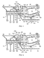
- a further cooling arrangement 124 according to the present invention is shown in figure 4 .
- the cooling arrangement 124 is similar to that shown in figures 2 and 3 .
- the cooling arrangement 124 comprises a cooling air manifold, for example an annular cooling air manifold, 138 located axially between the high pressure compressor 14 and the combustion chamber 15 and located radially between the diffuser 37 of the high pressure compressor 14 and the outer casing 20.
- the compressor outlet guide vanes 28 carry a plurality of aerodynamic fairings 40, the aerodynamic fairings 40 are positioned axially downstream of the compressor outlet guide vanes 28 and extend radially between the radially inner wall 34 and the radially outer wall 36 in the diffuser 37.
- the cooling arrangement comprise 124 a support structure 142 provided to support the cooling air manifold 138 from the inner casing 22 and the support structure 142 supports the cooling air manifold 138 from the inner casing 22 at two spaced positions.
- the support structure 142 supports the cooling air manifold 138 from the inner casing 22 at two axially spaced positions and in particular an axially downstream end 143 of the support structure 142 is secured to the inner casing 22 by a sliding joint 144 and the axially upstream end 145 of the support structure 142 is mounted on the radially inner wall 34 of the compressor outlet guide vanes 28 by a seal 146.
- the downstream end 143 of the support structure 142 locates in an annular slot 147 in the inner casing 22 so that relative axial movement is permitted between the inner casing 22 and the support structure 142.
- the cooling arrangement 124 also comprises a plurality of hollow ducts 148 and each hollow duct 148 locates behind a respective one of the aerodynamic fairings 40.
- Each hollow duct 148 extends radially across the diffuser 37 from the cooling air manifold 138 to the support structure 142 and within and behind the respective one of the aerodynamic fairings 40.
- the support structure 142 forms a chamber, for example an annular chamber, 150 with the inner casing 22.
- the inner casing 22 surrounds the first shaft 26 to form an annular chamber 66 and the inner casing 22 has a plurality of apertures 64 extending there-through interconnecting the annular chamber 50 and the annular chamber 66 and has another plurality of apertures 164 extending there-through interconnecting the annular chamber 50 and the annular chamber 66.
- the downstream end of the annular chamber 66 has a plurality of nozzles 68 to direct cooling air onto the high pressure turbine disc 21.
- An additional support structure 152 is provided to support the cooling air manifold 138 from the outer casing 20 and in particular an upstream end 153 of the additional support structure 152 is secured to the outer casing 20 by the flanged joint 32.
- the axially downstream end of the additional support structure 152 is secured to the cooling air manifold 138.
- the seal 146 is a ring seal and may be a piston ring seal, a brush seal or a labyrinth seal or any other suitable seal.
- a chamber 54 is defined by the casing 20 and the high pressure compressor 14 is arranged to supply air into the chamber 54.
- a duct 56 is provided to supply air from the chamber 54 to a heat exchanger 58 and a duct 60 is provided to return the air, after cooling in the heat exchanger 58, to the cooling air manifold 38.
- the heat exchanger 58 is positioned in the bypass duct 62 of the turbofan gas turbine engine 10.
- the air supplied to the chamber 54 is at the high pressure compressor 14 delivery pressure, e.g. the air is supplied from the outlet, at the downstream end, of the high pressure compressor 14 through the diffuser 37 into the chamber 54. It may be possible to bleed and supply air from other suitable regions of the high pressure compressor 14 if they are at a high enough pressure to drive air through the cooling arrangement 24.
- the additional support structure 152 may comprise a continuous frusto-conical casing or may comprise a plurality of beams extending from the flanged joint 32. The use of a plurality of beams would improve stressing during transient thermal loading and also reduce weight.
- the downstream end 143 of the support structure 142 interfaces with the inner casing 22 via a sliding joint 144 positioned axialy downstream of flanged joint 156 connecting portions of the inner casing 22. This enables annular chamber 150 to have a longer axial length and the cooled bleed air, cooled cooling air, may be supplied through the apertures 164 into the annular chamber 66.
- the flanged joint 156 connecting portions of the inner casing 22 is completely shielded from the combustion chamber 15 air.
- the cooled bleed air, cooled cooling air, is able to flow over and cool the flanged joint 156 as it flow to the apertures 164.
- the cooling arrangement 124 of figure 4 operates in substantially the same manner as that described in figures 2 and 3 .
- a further cooling arrangement 224 according to the present invention is shown in figure 5 .
- the cooling arrangement 224 is similar to that shown in figures 2 and 3 .
- the cooling arrangement 224 comprises a cooling air manifold, for example an annular cooling air manifold, 238 located axially between the high pressure compressor 14 and the combustion chamber 15 and located radially between the diffuser 37 of the high pressure compressor 14 and the outer casing 20.
- the compressor outlet guide vanes 28 carry a plurality of aerodynamic fairings 40, the aerodynamic fairings 40 are positioned axially downstream of the compressor outlet guide vanes 28 and extend radially between the radially inner wall 34 and the radially outer wall 36 in the diffuser 37.
- the cooling arrangement 224 comprises a support structure 242 provided to support the cooling air manifold 238 from the inner casing 22 and the support structure 242 supports the cooling air manifold 238 from the inner casing 22 at two spaced positions.
- the support structure 242 supports the cooling air manifold 238 from the inner casing 22 at two axially spaced positions and in particular an axially downstream end 243 of the support structure 242 is mounted on the inner casing 22 by a seal 244 and the axially upstream end 245 of the support structure 242 is mounted on the radially inner wall 34 of the compressor outlet guide vanes 28 by a seal 246.
- the cooling arrangement 224 also comprises a plurality of hollow ducts 248 and each hollow duct 248 locates behind a respective one of the aerodynamic fairings 40.
- Each hollow duct 248 extends radially across the diffuser 37 from the cooling air manifold 238 to the support structure 242 and within and behind the respective one of the aerodynamic fairings 40.
- the support structure 242 forms a chamber, for example an annular chamber, 250 with the inner casing 22.
- the inner casing 22 surrounds the first shaft 26 to form an annular chamber 66 and the inner casing 22 has a plurality of apertures 64 extending there-through interconnecting the annular chamber 250 and the annular chamber 66.
- the downstream end of the annular chamber 66 has a plurality of nozzles 68 to direct cooling air onto the high pressure turbine disc 21.
- An additional support structure 252 is provided to support the cooling air manifold 238 from the outer casing 20 and in particular an upstream end 253 of the additional support structure 252 is secured to the outer casing 20 by the flanged joint 32.
- the axially downstream end of the additional support structure 252 is secured to the cooling air manifold 238.
- the seals 244 and 246 are ring seals and may be piston ring seals, brush seals or labyrinth seals or any other suitable seals.
- a chamber 54 is defined by the casing 20 and the high pressure compressor 14 is arranged to supply air into the chamber 54.
- a duct 56 is provided to supply air from the chamber 54 to a heat exchanger 58 and a duct 60 is provided to return the air, after cooling in the heat exchanger 58, to the cooling air manifold 38.
- the heat exchanger 58 is positioned in the bypass duct 62 of the turbofan gas turbine engine 10.
- the air supplied to the chamber 54 is at the high pressure compressor 14 delivery pressure, e.g. the air is supplied from the outlet, at the downstream end, of the high pressure compressor 14 through the diffuser 37 into the chamber 54. It may be possible to bleed and supply air from other suitable regions of the high pressure compressor 14 if they are at a high enough pressure to drive air through the cooling arrangement 24.
- the additional support structure 252 may also comprise a continuous frusto-conical casing or may comprise a plurality of beams extending from the flanged joint 254. The use of a plurality of beams would improve stressing during transient thermal loading and also reduce weight.
- the cooling arrangement 224 of figure 5 operates in substantially the same manner as that described in figures 2 and 3 .
- a further cooling arrangement according to the present invention is similar to that shown in figures 2 and 3 .
- the cooling arrangement is similar to that in figures 2 and 3 in that the support structure is secured to the inner casing by a flanged joint.
- the cooling arrangement is similar to that in figure 4 in that the downstream end of the support structure locates in an annular slot in the inner casing so that relative axial movement is permitted between the downstream end of the inner casing and the support structure.
- a radially inwardly extending flange of the support structure which forms the flanged joint has a plurality of circumferentially spaced apertures arranged radially between the inner casing and the support structure.
- the inner casing has a plurality of apertures positioned downstream of the flanged joint, as in figure 4 , to allow the air to flow from the chamber between the inner casing and the support structure through the apertures in the flange and then through the apertures in the inner casing to the nozzles to direct cooling air onto the high pressure turbine disc.
- This cooling arrangement may be used with or without the additional support structure shown in figure 4 .
- the present invention has been described with reference to a turbofan gas turbine engine having a bypass duct and the heat exchanger may be arranged in the bypass duct of the turbofan gas turbine engine, it may be possible to position the heat exchanger in other positions on the gas turbine engine or associated aircraft, ship, land vehicle or building such that it is cooled by air.
- the fuel in the gas turbine engine fuel system may be used to cool the bleed air from the compressor in which case the heat exchanger is arranged in the fuel system of the gas turbine engine and the air supplied by the compressor is cooled by the fuel.
- the air supplied by the compressor may be cooled by water in the case of an industrial or marine gas turbine engine.
- the support structure has been described as being annular and arranged around the inner casing to form an annular chamber with the inner casing, it may be possible for the support structure to comprise part annular segments to form a plurality of chambers with the inner casing.
- the present invention is applicable to any type of gas turbine engine, for example a turbofan gas turbine engine, a turbojet gas turbine engine, a turboprop gas turbine engine or turboshaft gas turbine engine and is applicable to aero gas turbine engines, industrial gas turbine engines, marine gas turbine engines and automotive gas turbine engines.
- gas turbine engine for example a turbofan gas turbine engine, a turbojet gas turbine engine, a turboprop gas turbine engine or turboshaft gas turbine engine and is applicable to aero gas turbine engines, industrial gas turbine engines, marine gas turbine engines and automotive gas turbine engines.
Landscapes
- Engineering & Computer Science (AREA)
- Mechanical Engineering (AREA)
- General Engineering & Computer Science (AREA)
- Chemical & Material Sciences (AREA)
- Combustion & Propulsion (AREA)
- Physics & Mathematics (AREA)
- Fluid Mechanics (AREA)
- Turbine Rotor Nozzle Sealing (AREA)
Applications Claiming Priority (1)
| Application Number | Priority Date | Filing Date | Title |
|---|---|---|---|
| GBGB1305432.5A GB201305432D0 (en) | 2013-03-26 | 2013-03-26 | A gas turbine engine cooling arrangement |
Publications (3)
| Publication Number | Publication Date |
|---|---|
| EP2784267A2 true EP2784267A2 (fr) | 2014-10-01 |
| EP2784267A3 EP2784267A3 (fr) | 2015-04-15 |
| EP2784267B1 EP2784267B1 (fr) | 2018-07-25 |
Family
ID=48326615
Family Applications (1)
| Application Number | Title | Priority Date | Filing Date |
|---|---|---|---|
| EP14158097.7A Not-in-force EP2784267B1 (fr) | 2013-03-26 | 2014-03-06 | Moteur de turbine à gaz avec dispositif de refroidissement |
Country Status (3)
| Country | Link |
|---|---|
| US (1) | US10087775B2 (fr) |
| EP (1) | EP2784267B1 (fr) |
| GB (1) | GB201305432D0 (fr) |
Cited By (3)
| Publication number | Priority date | Publication date | Assignee | Title |
|---|---|---|---|---|
| EP3739170A1 (fr) * | 2019-05-15 | 2020-11-18 | Raytheon Technologies Corporation | Structure de support de carter de diffusion |
| EP4033073A1 (fr) * | 2021-01-25 | 2022-07-27 | Siemens Energy Global GmbH & Co. KG | Section de combustion dotée d'un blindage de boîtier |
| US12104533B2 (en) | 2020-04-24 | 2024-10-01 | General Electric Company | Methods and apparatus for gas turbine frame flow path hardware cooling |
Families Citing this family (27)
| Publication number | Priority date | Publication date | Assignee | Title |
|---|---|---|---|---|
| US11732892B2 (en) | 2013-08-14 | 2023-08-22 | General Electric Company | Gas turbomachine diffuser assembly with radial flow splitters |
| US10107200B2 (en) | 2015-04-30 | 2018-10-23 | General Electric Company | Turbine engine thermal management |
| EP3109433B1 (fr) * | 2015-06-19 | 2018-08-15 | Rolls-Royce Corporation | Moteur entraîné par cycle sc02 avec des arbres indépendants pour éléments de cycle de combustion et éléments de propulsion |
| US20170138595A1 (en) * | 2015-11-18 | 2017-05-18 | General Electric Company | Combustor Wall Channel Cooling System |
| GB201610080D0 (en) * | 2016-06-09 | 2016-07-27 | Rolls Royce Plc | Multi-stage compressor with multiple bleed plenums |
| US10436115B2 (en) * | 2016-08-22 | 2019-10-08 | United Technologies Corporation | Heat exchanger for gas turbine engine with support damper mounting |
| US10443620B2 (en) * | 2018-01-02 | 2019-10-15 | General Electric Company | Heat dissipation system for electric aircraft engine |
| US11060530B2 (en) * | 2018-01-04 | 2021-07-13 | General Electric Company | Compressor cooling in a gas turbine engine |
| US10816205B2 (en) * | 2018-05-30 | 2020-10-27 | Raytheon Technologies Corporation | Thermally isolated combustor pre-diffuser |
| US10941669B2 (en) | 2018-12-21 | 2021-03-09 | Raytheon Technologies Corporation | Diffuser case support structure |
| US11022144B2 (en) * | 2019-03-22 | 2021-06-01 | Raytheon Technologies Corporation | Diffuser case assembly |
| CN110206591A (zh) * | 2019-06-04 | 2019-09-06 | 中国船舶重工集团公司第七0三研究所 | 一种用于涡轮动叶供气的槽道式冷却空气导向装置 |
| CN111058906B (zh) * | 2020-01-19 | 2024-09-13 | 重庆江增船舶重工有限公司 | 一种应用于超临界二氧化碳透平的冷却结构、方法 |
| JP7412529B2 (ja) * | 2020-02-20 | 2024-01-12 | 川崎重工業株式会社 | ガスタービンエンジンのフランジ冷却構造 |
| US11460191B2 (en) | 2020-08-31 | 2022-10-04 | General Electric Company | Cooling insert for a turbomachine |
| US11614233B2 (en) | 2020-08-31 | 2023-03-28 | General Electric Company | Impingement panel support structure and method of manufacture |
| US11994292B2 (en) | 2020-08-31 | 2024-05-28 | General Electric Company | Impingement cooling apparatus for turbomachine |
| US11371702B2 (en) | 2020-08-31 | 2022-06-28 | General Electric Company | Impingement panel for a turbomachine |
| US11994293B2 (en) | 2020-08-31 | 2024-05-28 | General Electric Company | Impingement cooling apparatus support structure and method of manufacture |
| CN114278401B (zh) * | 2020-09-28 | 2024-04-26 | 中国航发商用航空发动机有限责任公司 | 涡轮式发动机的涡轮机匣和涡轮式发动机 |
| US11255545B1 (en) | 2020-10-26 | 2022-02-22 | General Electric Company | Integrated combustion nozzle having a unified head end |
| US11674396B2 (en) | 2021-07-30 | 2023-06-13 | General Electric Company | Cooling air delivery assembly |
| US11767766B1 (en) | 2022-07-29 | 2023-09-26 | General Electric Company | Turbomachine airfoil having impingement cooling passages |
| US12044172B2 (en) | 2022-11-02 | 2024-07-23 | General Electric Company | Air guide for a gas turbine engine |
| US12366201B2 (en) | 2023-02-17 | 2025-07-22 | General Electric Company | Reverse flow gas turbine engine having electric machine |
| US12698901B2 (en) * | 2023-06-09 | 2026-08-04 | Rtx Corporation | Gas turbine engine with improved high pressure compressor leakage path guide structure |
| US12071913B1 (en) * | 2023-07-31 | 2024-08-27 | Rolls-Royce North American Technologies Inc. | Inlets for gas turbine engine bypass duct heat exchangers |
Family Cites Families (28)
| Publication number | Priority date | Publication date | Assignee | Title |
|---|---|---|---|---|
| GB630277A (en) | 1947-02-12 | 1949-10-10 | Adrian Albert Lombard | Improvements relating to axial-flow compressors |
| US2961150A (en) | 1958-12-30 | 1960-11-22 | Gen Electric | Frame structure for turbo-machine |
| US3452542A (en) | 1966-09-30 | 1969-07-01 | Gen Electric | Gas turbine engine cooling system |
| US3989410A (en) * | 1974-11-27 | 1976-11-02 | General Electric Company | Labyrinth seal system |
| US4183207A (en) | 1978-03-07 | 1980-01-15 | Avco Corporation | Oil-conducting strut for turbine engines |
| FR2656657A1 (fr) | 1989-12-28 | 1991-07-05 | Snecma | Turbomachine refroidie par air et procede de refroidissement de cette turbomachine. |
| US5123242A (en) * | 1990-07-30 | 1992-06-23 | General Electric Company | Precooling heat exchange arrangement integral with mounting structure fairing of gas turbine engine |
| US5156525A (en) * | 1991-02-26 | 1992-10-20 | General Electric Company | Turbine assembly |
| US5269133A (en) * | 1991-06-18 | 1993-12-14 | General Electric Company | Heat exchanger for cooling a gas turbine |
| US5249921A (en) * | 1991-12-23 | 1993-10-05 | General Electric Company | Compressor outlet guide vane support |
| US5292227A (en) | 1992-12-10 | 1994-03-08 | General Electric Company | Turbine frame |
| US5619855A (en) * | 1995-06-07 | 1997-04-15 | General Electric Company | High inlet mach combustor for gas turbine engine |
| US5609467A (en) | 1995-09-28 | 1997-03-11 | Cooper Cameron Corporation | Floating interturbine duct assembly for high temperature power turbine |
| US7284378B2 (en) * | 2004-06-04 | 2007-10-23 | General Electric Company | Methods and apparatus for low emission gas turbine energy generation |
| US7303372B2 (en) * | 2005-11-18 | 2007-12-04 | General Electric Company | Methods and apparatus for cooling combustion turbine engine components |
| JP2008082247A (ja) * | 2006-09-27 | 2008-04-10 | Mitsubishi Heavy Ind Ltd | ガスタービン |
| EP1950382A1 (fr) * | 2007-01-29 | 2008-07-30 | Siemens Aktiengesellschaft | Entretoise avec élément de guidage de flux |
| US7954324B2 (en) * | 2007-04-05 | 2011-06-07 | Siemens Energy, Inc. | Gas turbine engine |
| US20080276622A1 (en) * | 2007-05-07 | 2008-11-13 | Thomas Edward Johnson | Fuel nozzle and method of fabricating the same |
| US8438854B2 (en) | 2008-05-23 | 2013-05-14 | Honeywell International Inc. | Pre-diffuser for centrifugal compressor |
| US8231142B2 (en) | 2009-02-17 | 2012-07-31 | Pratt & Whitney Canada Corp. | Fluid conduit coupling with leakage detection |
| US20100303610A1 (en) | 2009-05-29 | 2010-12-02 | United Technologies Corporation | Cooled gas turbine stator assembly |
| US8307662B2 (en) * | 2009-10-15 | 2012-11-13 | General Electric Company | Gas turbine engine temperature modulated cooling flow |
| GB201001974D0 (en) * | 2010-02-08 | 2010-03-24 | Rolls Royce Plc | An outlet guide vane structure |
| US8961114B2 (en) * | 2010-11-22 | 2015-02-24 | General Electric Company | Integrated variable geometry flow restrictor and heat exchanger |
| US20120151928A1 (en) * | 2010-12-17 | 2012-06-21 | Nayan Vinodbhai Patel | Cooling flowpath dirt deflector in fuel nozzle |
| EP3055535A4 (fr) * | 2013-10-07 | 2016-10-05 | United Technologies Corp | Passage de refroidissement à revêtement arrière |
| US20180080476A1 (en) * | 2016-09-19 | 2018-03-22 | United Technologies Corporation | Geared turbofan front center body thermal management |
-
2013
- 2013-03-26 GB GBGB1305432.5A patent/GB201305432D0/en not_active Ceased
-
2014
- 2014-03-06 EP EP14158097.7A patent/EP2784267B1/fr not_active Not-in-force
- 2014-03-06 US US14/199,099 patent/US10087775B2/en active Active
Cited By (6)
| Publication number | Priority date | Publication date | Assignee | Title |
|---|---|---|---|---|
| EP3739170A1 (fr) * | 2019-05-15 | 2020-11-18 | Raytheon Technologies Corporation | Structure de support de carter de diffusion |
| US11236677B2 (en) | 2019-05-15 | 2022-02-01 | Raytheon Technologies Corporation | Diffuser case support structure |
| US12104533B2 (en) | 2020-04-24 | 2024-10-01 | General Electric Company | Methods and apparatus for gas turbine frame flow path hardware cooling |
| EP4033073A1 (fr) * | 2021-01-25 | 2022-07-27 | Siemens Energy Global GmbH & Co. KG | Section de combustion dotée d'un blindage de boîtier |
| WO2022156925A1 (fr) * | 2021-01-25 | 2022-07-28 | Siemens Energy Global GmbH & Co. KG | Section de combustion dotée d'un blindage de carter |
| US12215864B2 (en) | 2021-01-25 | 2025-02-04 | Siemens Energy Global GmbH & Co. KG | Combustion section with a casing shielding |
Also Published As
| Publication number | Publication date |
|---|---|
| GB201305432D0 (en) | 2013-05-08 |
| US20140290272A1 (en) | 2014-10-02 |
| EP2784267A3 (fr) | 2015-04-15 |
| EP2784267B1 (fr) | 2018-07-25 |
| US10087775B2 (en) | 2018-10-02 |
Similar Documents
| Publication | Publication Date | Title |
|---|---|---|
| EP2784267B1 (fr) | Moteur de turbine à gaz avec dispositif de refroidissement | |
| US11021990B2 (en) | Shroud sealing for a gas turbine engine | |
| EP3241994B1 (fr) | Système et procédé permettant de refroidir des composants d'un moteur à turbine à gaz | |
| US9677412B2 (en) | Shroud arrangement for a gas turbine engine | |
| US10989411B2 (en) | Heat exchanger for turbo machine | |
| US9611754B2 (en) | Shroud arrangement for a gas turbine engine | |
| CA2843075C (fr) | Section d'echappement pour turbines a gaz de derivation | |
| EP2938859B1 (fr) | Architecture de refroidissement destinée à un carter d'échappement de turbine | |
| US10400627B2 (en) | System for cooling a turbine engine | |
| US9920647B2 (en) | Dual source cooling air shroud arrangement for a gas turbine engine | |
| US9689273B2 (en) | Shroud arrangement for a gas turbine engine | |
| CN106050315B (zh) | 涡轮排气框架和导叶组装的方法 | |
| US20190136714A1 (en) | Modulated turbine cooling system | |
| EP3214274B1 (fr) | Refroidissement encapsulé pour viroles de turbine | |
| US10697372B2 (en) | Turbine engine conduit interface | |
| US11286882B2 (en) | Exhaust casing for a gas turbine engine | |
| US10036263B2 (en) | Stator assembly with pad interface for a gas turbine engine | |
| EP3848570B1 (fr) | Système de refroidissement pour un moteur à turbine à gaz | |
| CA3263698A1 (fr) | Système de refroidissement d’injecteur |
Legal Events
| Date | Code | Title | Description |
|---|---|---|---|
| 17P | Request for examination filed |
Effective date: 20140306 |
|
| AK | Designated contracting states |
Kind code of ref document: A2 Designated state(s): AL AT BE BG CH CY CZ DE DK EE ES FI FR GB GR HR HU IE IS IT LI LT LU LV MC MK MT NL NO PL PT RO RS SE SI SK SM TR |
|
| AX | Request for extension of the european patent |
Extension state: BA ME |
|
| PUAI | Public reference made under article 153(3) epc to a published international application that has entered the european phase |
Free format text: ORIGINAL CODE: 0009012 |
|
| PUAL | Search report despatched |
Free format text: ORIGINAL CODE: 0009013 |
|
| AK | Designated contracting states |
Kind code of ref document: A3 Designated state(s): AL AT BE BG CH CY CZ DE DK EE ES FI FR GB GR HR HU IE IS IT LI LT LU LV MC MK MT NL NO PL PT RO RS SE SI SK SM TR |
|
| AX | Request for extension of the european patent |
Extension state: BA ME |
|
| RIC1 | Information provided on ipc code assigned before grant |
Ipc: F02C 6/08 20060101ALI20150312BHEP Ipc: F01D 25/24 20060101ALI20150312BHEP Ipc: F02C 7/18 20060101ALI20150312BHEP Ipc: F01D 5/08 20060101ALI20150312BHEP Ipc: F01D 9/06 20060101AFI20150312BHEP Ipc: F04D 29/54 20060101ALI20150312BHEP |
|
| RAP1 | Party data changed (applicant data changed or rights of an application transferred) |
Owner name: ROLLS-ROYCE PLC |
|
| R17P | Request for examination filed (corrected) |
Effective date: 20151006 |
|
| RBV | Designated contracting states (corrected) |
Designated state(s): AL AT BE BG CH CY CZ DE DK EE ES FI FR GB GR HR HU IE IS IT LI LT LU LV MC MK MT NL NO PL PT RO RS SE SI SK SM TR |
|
| GRAP | Despatch of communication of intention to grant a patent |
Free format text: ORIGINAL CODE: EPIDOSNIGR1 |
|
| STAA | Information on the status of an ep patent application or granted ep patent |
Free format text: STATUS: GRANT OF PATENT IS INTENDED |
|
| INTG | Intention to grant announced |
Effective date: 20180412 |
|
| GRAS | Grant fee paid |
Free format text: ORIGINAL CODE: EPIDOSNIGR3 |
|
| GRAA | (expected) grant |
Free format text: ORIGINAL CODE: 0009210 |
|
| STAA | Information on the status of an ep patent application or granted ep patent |
Free format text: STATUS: THE PATENT HAS BEEN GRANTED |
|
| AK | Designated contracting states |
Kind code of ref document: B1 Designated state(s): AL AT BE BG CH CY CZ DE DK EE ES FI FR GB GR HR HU IE IS IT LI LT LU LV MC MK MT NL NO PL PT RO RS SE SI SK SM TR |
|
| REG | Reference to a national code |
Ref country code: GB Ref legal event code: FG4D |
|
| REG | Reference to a national code |
Ref country code: CH Ref legal event code: EP |
|
| REG | Reference to a national code |
Ref country code: AT Ref legal event code: REF Ref document number: 1021988 Country of ref document: AT Kind code of ref document: T Effective date: 20180815 |
|
| REG | Reference to a national code |
Ref country code: IE Ref legal event code: FG4D |
|
| REG | Reference to a national code |
Ref country code: DE Ref legal event code: R096 Ref document number: 602014028970 Country of ref document: DE |
|
| REG | Reference to a national code |
Ref country code: NL Ref legal event code: MP Effective date: 20180725 |
|
| REG | Reference to a national code |
Ref country code: LT Ref legal event code: MG4D |
|
| PG25 | Lapsed in a contracting state [announced via postgrant information from national office to epo] |
Ref country code: NL Free format text: LAPSE BECAUSE OF FAILURE TO SUBMIT A TRANSLATION OF THE DESCRIPTION OR TO PAY THE FEE WITHIN THE PRESCRIBED TIME-LIMIT Effective date: 20180725 |
|
| REG | Reference to a national code |
Ref country code: AT Ref legal event code: MK05 Ref document number: 1021988 Country of ref document: AT Kind code of ref document: T Effective date: 20180725 |
|
| PG25 | Lapsed in a contracting state [announced via postgrant information from national office to epo] |
Ref country code: AT Free format text: LAPSE BECAUSE OF FAILURE TO SUBMIT A TRANSLATION OF THE DESCRIPTION OR TO PAY THE FEE WITHIN THE PRESCRIBED TIME-LIMIT Effective date: 20180725 Ref country code: SE Free format text: LAPSE BECAUSE OF FAILURE TO SUBMIT A TRANSLATION OF THE DESCRIPTION OR TO PAY THE FEE WITHIN THE PRESCRIBED TIME-LIMIT Effective date: 20180725 Ref country code: BG Free format text: LAPSE BECAUSE OF FAILURE TO SUBMIT A TRANSLATION OF THE DESCRIPTION OR TO PAY THE FEE WITHIN THE PRESCRIBED TIME-LIMIT Effective date: 20181025 Ref country code: IS Free format text: LAPSE BECAUSE OF FAILURE TO SUBMIT A TRANSLATION OF THE DESCRIPTION OR TO PAY THE FEE WITHIN THE PRESCRIBED TIME-LIMIT Effective date: 20181125 Ref country code: PL Free format text: LAPSE BECAUSE OF FAILURE TO SUBMIT A TRANSLATION OF THE DESCRIPTION OR TO PAY THE FEE WITHIN THE PRESCRIBED TIME-LIMIT Effective date: 20180725 Ref country code: NO Free format text: LAPSE BECAUSE OF FAILURE TO SUBMIT A TRANSLATION OF THE DESCRIPTION OR TO PAY THE FEE WITHIN THE PRESCRIBED TIME-LIMIT Effective date: 20181025 Ref country code: LT Free format text: LAPSE BECAUSE OF FAILURE TO SUBMIT A TRANSLATION OF THE DESCRIPTION OR TO PAY THE FEE WITHIN THE PRESCRIBED TIME-LIMIT Effective date: 20180725 Ref country code: GR Free format text: LAPSE BECAUSE OF FAILURE TO SUBMIT A TRANSLATION OF THE DESCRIPTION OR TO PAY THE FEE WITHIN THE PRESCRIBED TIME-LIMIT Effective date: 20181026 Ref country code: RS Free format text: LAPSE BECAUSE OF FAILURE TO SUBMIT A TRANSLATION OF THE DESCRIPTION OR TO PAY THE FEE WITHIN THE PRESCRIBED TIME-LIMIT Effective date: 20180725 Ref country code: FI Free format text: LAPSE BECAUSE OF FAILURE TO SUBMIT A TRANSLATION OF THE DESCRIPTION OR TO PAY THE FEE WITHIN THE PRESCRIBED TIME-LIMIT Effective date: 20180725 |
|
| PG25 | Lapsed in a contracting state [announced via postgrant information from national office to epo] |
Ref country code: LV Free format text: LAPSE BECAUSE OF FAILURE TO SUBMIT A TRANSLATION OF THE DESCRIPTION OR TO PAY THE FEE WITHIN THE PRESCRIBED TIME-LIMIT Effective date: 20180725 Ref country code: AL Free format text: LAPSE BECAUSE OF FAILURE TO SUBMIT A TRANSLATION OF THE DESCRIPTION OR TO PAY THE FEE WITHIN THE PRESCRIBED TIME-LIMIT Effective date: 20180725 Ref country code: HR Free format text: LAPSE BECAUSE OF FAILURE TO SUBMIT A TRANSLATION OF THE DESCRIPTION OR TO PAY THE FEE WITHIN THE PRESCRIBED TIME-LIMIT Effective date: 20180725 |
|
| REG | Reference to a national code |
Ref country code: DE Ref legal event code: R097 Ref document number: 602014028970 Country of ref document: DE |
|
| PG25 | Lapsed in a contracting state [announced via postgrant information from national office to epo] |
Ref country code: IT Free format text: LAPSE BECAUSE OF FAILURE TO SUBMIT A TRANSLATION OF THE DESCRIPTION OR TO PAY THE FEE WITHIN THE PRESCRIBED TIME-LIMIT Effective date: 20180725 Ref country code: ES Free format text: LAPSE BECAUSE OF FAILURE TO SUBMIT A TRANSLATION OF THE DESCRIPTION OR TO PAY THE FEE WITHIN THE PRESCRIBED TIME-LIMIT Effective date: 20180725 Ref country code: EE Free format text: LAPSE BECAUSE OF FAILURE TO SUBMIT A TRANSLATION OF THE DESCRIPTION OR TO PAY THE FEE WITHIN THE PRESCRIBED TIME-LIMIT Effective date: 20180725 Ref country code: CZ Free format text: LAPSE BECAUSE OF FAILURE TO SUBMIT A TRANSLATION OF THE DESCRIPTION OR TO PAY THE FEE WITHIN THE PRESCRIBED TIME-LIMIT Effective date: 20180725 Ref country code: RO Free format text: LAPSE BECAUSE OF FAILURE TO SUBMIT A TRANSLATION OF THE DESCRIPTION OR TO PAY THE FEE WITHIN THE PRESCRIBED TIME-LIMIT Effective date: 20180725 |
|
| PG25 | Lapsed in a contracting state [announced via postgrant information from national office to epo] |
Ref country code: SM Free format text: LAPSE BECAUSE OF FAILURE TO SUBMIT A TRANSLATION OF THE DESCRIPTION OR TO PAY THE FEE WITHIN THE PRESCRIBED TIME-LIMIT Effective date: 20180725 Ref country code: DK Free format text: LAPSE BECAUSE OF FAILURE TO SUBMIT A TRANSLATION OF THE DESCRIPTION OR TO PAY THE FEE WITHIN THE PRESCRIBED TIME-LIMIT Effective date: 20180725 Ref country code: SK Free format text: LAPSE BECAUSE OF FAILURE TO SUBMIT A TRANSLATION OF THE DESCRIPTION OR TO PAY THE FEE WITHIN THE PRESCRIBED TIME-LIMIT Effective date: 20180725 |
|
| PLBE | No opposition filed within time limit |
Free format text: ORIGINAL CODE: 0009261 |
|
| STAA | Information on the status of an ep patent application or granted ep patent |
Free format text: STATUS: NO OPPOSITION FILED WITHIN TIME LIMIT |
|
| 26N | No opposition filed |
Effective date: 20190426 |
|
| PG25 | Lapsed in a contracting state [announced via postgrant information from national office to epo] |
Ref country code: SI Free format text: LAPSE BECAUSE OF FAILURE TO SUBMIT A TRANSLATION OF THE DESCRIPTION OR TO PAY THE FEE WITHIN THE PRESCRIBED TIME-LIMIT Effective date: 20180725 |
|
| PG25 | Lapsed in a contracting state [announced via postgrant information from national office to epo] |
Ref country code: MC Free format text: LAPSE BECAUSE OF FAILURE TO SUBMIT A TRANSLATION OF THE DESCRIPTION OR TO PAY THE FEE WITHIN THE PRESCRIBED TIME-LIMIT Effective date: 20180725 |
|
| REG | Reference to a national code |
Ref country code: CH Ref legal event code: PL |
|
| PG25 | Lapsed in a contracting state [announced via postgrant information from national office to epo] |
Ref country code: LU Free format text: LAPSE BECAUSE OF NON-PAYMENT OF DUE FEES Effective date: 20190306 |
|
| REG | Reference to a national code |
Ref country code: BE Ref legal event code: MM Effective date: 20190331 |
|
| PG25 | Lapsed in a contracting state [announced via postgrant information from national office to epo] |
Ref country code: IE Free format text: LAPSE BECAUSE OF NON-PAYMENT OF DUE FEES Effective date: 20190306 Ref country code: CH Free format text: LAPSE BECAUSE OF NON-PAYMENT OF DUE FEES Effective date: 20190331 Ref country code: LI Free format text: LAPSE BECAUSE OF NON-PAYMENT OF DUE FEES Effective date: 20190331 |
|
| PG25 | Lapsed in a contracting state [announced via postgrant information from national office to epo] |
Ref country code: BE Free format text: LAPSE BECAUSE OF NON-PAYMENT OF DUE FEES Effective date: 20190331 |
|
| PG25 | Lapsed in a contracting state [announced via postgrant information from national office to epo] |
Ref country code: TR Free format text: LAPSE BECAUSE OF FAILURE TO SUBMIT A TRANSLATION OF THE DESCRIPTION OR TO PAY THE FEE WITHIN THE PRESCRIBED TIME-LIMIT Effective date: 20180725 |
|
| PG25 | Lapsed in a contracting state [announced via postgrant information from national office to epo] |
Ref country code: PT Free format text: LAPSE BECAUSE OF FAILURE TO SUBMIT A TRANSLATION OF THE DESCRIPTION OR TO PAY THE FEE WITHIN THE PRESCRIBED TIME-LIMIT Effective date: 20181125 Ref country code: MT Free format text: LAPSE BECAUSE OF NON-PAYMENT OF DUE FEES Effective date: 20190306 |
|
| PG25 | Lapsed in a contracting state [announced via postgrant information from national office to epo] |
Ref country code: CY Free format text: LAPSE BECAUSE OF FAILURE TO SUBMIT A TRANSLATION OF THE DESCRIPTION OR TO PAY THE FEE WITHIN THE PRESCRIBED TIME-LIMIT Effective date: 20180725 |
|
| PG25 | Lapsed in a contracting state [announced via postgrant information from national office to epo] |
Ref country code: HU Free format text: LAPSE BECAUSE OF FAILURE TO SUBMIT A TRANSLATION OF THE DESCRIPTION OR TO PAY THE FEE WITHIN THE PRESCRIBED TIME-LIMIT; INVALID AB INITIO Effective date: 20140306 |
|
| PGFP | Annual fee paid to national office [announced via postgrant information from national office to epo] |
Ref country code: DE Payment date: 20210527 Year of fee payment: 8 |
|
| PGFP | Annual fee paid to national office [announced via postgrant information from national office to epo] |
Ref country code: GB Payment date: 20220322 Year of fee payment: 9 |
|
| PGFP | Annual fee paid to national office [announced via postgrant information from national office to epo] |
Ref country code: FR Payment date: 20220325 Year of fee payment: 9 |
|
| PG25 | Lapsed in a contracting state [announced via postgrant information from national office to epo] |
Ref country code: MK Free format text: LAPSE BECAUSE OF FAILURE TO SUBMIT A TRANSLATION OF THE DESCRIPTION OR TO PAY THE FEE WITHIN THE PRESCRIBED TIME-LIMIT Effective date: 20180725 |
|
| REG | Reference to a national code |
Ref country code: DE Ref legal event code: R119 Ref document number: 602014028970 Country of ref document: DE |
|
| PG25 | Lapsed in a contracting state [announced via postgrant information from national office to epo] |
Ref country code: DE Free format text: LAPSE BECAUSE OF NON-PAYMENT OF DUE FEES Effective date: 20221001 |
|
| P01 | Opt-out of the competence of the unified patent court (upc) registered |
Effective date: 20230528 |
|
| GBPC | Gb: european patent ceased through non-payment of renewal fee |
Effective date: 20230306 |
|
| PG25 | Lapsed in a contracting state [announced via postgrant information from national office to epo] |
Ref country code: GB Free format text: LAPSE BECAUSE OF NON-PAYMENT OF DUE FEES Effective date: 20230306 |
|
| PG25 | Lapsed in a contracting state [announced via postgrant information from national office to epo] |
Ref country code: GB Free format text: LAPSE BECAUSE OF NON-PAYMENT OF DUE FEES Effective date: 20230306 Ref country code: FR Free format text: LAPSE BECAUSE OF NON-PAYMENT OF DUE FEES Effective date: 20230331 |