EP2784299A1 - Dieselkraftstoffstabilisierung für verbesserte Verbrennung - Google Patents
Dieselkraftstoffstabilisierung für verbesserte Verbrennung Download PDFInfo
- Publication number
- EP2784299A1 EP2784299A1 EP14161635.9A EP14161635A EP2784299A1 EP 2784299 A1 EP2784299 A1 EP 2784299A1 EP 14161635 A EP14161635 A EP 14161635A EP 2784299 A1 EP2784299 A1 EP 2784299A1
- Authority
- EP
- European Patent Office
- Prior art keywords
- fuel
- diesel
- amount
- diesel fuel
- dissolved oxygen
- Prior art date
- Legal status (The legal status is an assumption and is not a legal conclusion. Google has not performed a legal analysis and makes no representation as to the accuracy of the status listed.)
- Withdrawn
Links
- 239000002283 diesel fuel Substances 0.000 title claims abstract description 52
- 238000002485 combustion reaction Methods 0.000 title 1
- 230000006641 stabilisation Effects 0.000 title 1
- 238000011105 stabilization Methods 0.000 title 1
- 239000000446 fuel Substances 0.000 claims abstract description 89
- QVGXLLKOCUKJST-UHFFFAOYSA-N atomic oxygen Chemical compound [O] QVGXLLKOCUKJST-UHFFFAOYSA-N 0.000 claims abstract description 43
- 238000006392 deoxygenation reaction Methods 0.000 claims abstract description 43
- 239000001301 oxygen Substances 0.000 claims abstract description 43
- 229910052760 oxygen Inorganic materials 0.000 claims abstract description 43
- XLYOFNOQVPJJNP-UHFFFAOYSA-N water Substances O XLYOFNOQVPJJNP-UHFFFAOYSA-N 0.000 claims description 27
- 239000012528 membrane Substances 0.000 claims description 20
- 238000001816 cooling Methods 0.000 claims description 3
- 238000011144 upstream manufacturing Methods 0.000 claims description 3
- 239000002918 waste heat Substances 0.000 claims description 2
- 238000006243 chemical reaction Methods 0.000 description 11
- 239000002245 particle Substances 0.000 description 6
- 239000004809 Teflon Substances 0.000 description 4
- 230000015572 biosynthetic process Effects 0.000 description 3
- 238000010586 diagram Methods 0.000 description 3
- 230000007246 mechanism Effects 0.000 description 3
- JSGITCLSCUKHFW-UHFFFAOYSA-N 2,2,4-trifluoro-5-(trifluoromethoxy)-1,3-dioxole Chemical compound FC1=C(OC(F)(F)F)OC(F)(F)O1 JSGITCLSCUKHFW-UHFFFAOYSA-N 0.000 description 2
- YSYRISKCBOPJRG-UHFFFAOYSA-N 4,5-difluoro-2,2-bis(trifluoromethyl)-1,3-dioxole Chemical compound FC1=C(F)OC(C(F)(F)F)(C(F)(F)F)O1 YSYRISKCBOPJRG-UHFFFAOYSA-N 0.000 description 2
- 229920001577 copolymer Polymers 0.000 description 2
- 238000009792 diffusion process Methods 0.000 description 2
- 239000007789 gas Substances 0.000 description 2
- 239000013535 sea water Substances 0.000 description 2
- 230000004075 alteration Effects 0.000 description 1
- 238000000889 atomisation Methods 0.000 description 1
- 239000002551 biofuel Substances 0.000 description 1
- 238000004140 cleaning Methods 0.000 description 1
- 238000004939 coking Methods 0.000 description 1
- 230000003247 decreasing effect Effects 0.000 description 1
- 230000000694 effects Effects 0.000 description 1
- 239000004811 fluoropolymer Substances 0.000 description 1
- 229920002313 fluoropolymer Polymers 0.000 description 1
- 238000010438 heat treatment Methods 0.000 description 1
- 238000002347 injection Methods 0.000 description 1
- 239000007924 injection Substances 0.000 description 1
- 239000007788 liquid Substances 0.000 description 1
- 239000000463 material Substances 0.000 description 1
- 238000007254 oxidation reaction Methods 0.000 description 1
- 239000003208 petroleum Substances 0.000 description 1
- 239000002861 polymer material Substances 0.000 description 1
- 239000011148 porous material Substances 0.000 description 1
- 230000009467 reduction Effects 0.000 description 1
- 229920006395 saturated elastomer Polymers 0.000 description 1
- 238000006467 substitution reaction Methods 0.000 description 1
- 239000002966 varnish Substances 0.000 description 1
Images


Classifications
-
- F—MECHANICAL ENGINEERING; LIGHTING; HEATING; WEAPONS; BLASTING
- F02—COMBUSTION ENGINES; HOT-GAS OR COMBUSTION-PRODUCT ENGINE PLANTS
- F02M—SUPPLYING COMBUSTION ENGINES IN GENERAL WITH COMBUSTIBLE MIXTURES OR CONSTITUENTS THEREOF
- F02M33/00—Other apparatus for treating combustion-air, fuel or fuel-air mixture
-
- B—PERFORMING OPERATIONS; TRANSPORTING
- B01—PHYSICAL OR CHEMICAL PROCESSES OR APPARATUS IN GENERAL
- B01D—SEPARATION
- B01D17/00—Separation of liquids, not provided for elsewhere, e.g. by thermal diffusion
- B01D17/02—Separation of non-miscible liquids
- B01D17/04—Breaking emulsions
- B01D17/044—Breaking emulsions by changing the pressure
-
- B—PERFORMING OPERATIONS; TRANSPORTING
- B01—PHYSICAL OR CHEMICAL PROCESSES OR APPARATUS IN GENERAL
- B01D—SEPARATION
- B01D17/00—Separation of liquids, not provided for elsewhere, e.g. by thermal diffusion
- B01D17/08—Thickening liquid suspensions by filtration
- B01D17/085—Thickening liquid suspensions by filtration with membranes
-
- F—MECHANICAL ENGINEERING; LIGHTING; HEATING; WEAPONS; BLASTING
- F02—COMBUSTION ENGINES; HOT-GAS OR COMBUSTION-PRODUCT ENGINE PLANTS
- F02M—SUPPLYING COMBUSTION ENGINES IN GENERAL WITH COMBUSTIBLE MIXTURES OR CONSTITUENTS THEREOF
- F02M31/00—Apparatus for thermally treating combustion-air, fuel, or fuel-air mixture
- F02M31/02—Apparatus for thermally treating combustion-air, fuel, or fuel-air mixture for heating
- F02M31/16—Other apparatus for heating fuel
-
- F—MECHANICAL ENGINEERING; LIGHTING; HEATING; WEAPONS; BLASTING
- F02—COMBUSTION ENGINES; HOT-GAS OR COMBUSTION-PRODUCT ENGINE PLANTS
- F02M—SUPPLYING COMBUSTION ENGINES IN GENERAL WITH COMBUSTIBLE MIXTURES OR CONSTITUENTS THEREOF
- F02M37/00—Apparatus or systems for feeding liquid fuel from storage containers to carburettors or fuel-injection apparatus; Arrangements for purifying liquid fuel specially adapted for, or arranged on, internal-combustion engines
- F02M37/22—Arrangements for purifying liquid fuel specially adapted for, or arranged on, internal-combustion engines, e.g. arrangements in the feeding system
- F02M37/24—Arrangements for purifying liquid fuel specially adapted for, or arranged on, internal-combustion engines, e.g. arrangements in the feeding system characterised by water separating means
-
- F—MECHANICAL ENGINEERING; LIGHTING; HEATING; WEAPONS; BLASTING
- F02—COMBUSTION ENGINES; HOT-GAS OR COMBUSTION-PRODUCT ENGINE PLANTS
- F02M—SUPPLYING COMBUSTION ENGINES IN GENERAL WITH COMBUSTIBLE MIXTURES OR CONSTITUENTS THEREOF
- F02M37/00—Apparatus or systems for feeding liquid fuel from storage containers to carburettors or fuel-injection apparatus; Arrangements for purifying liquid fuel specially adapted for, or arranged on, internal-combustion engines
- F02M37/22—Arrangements for purifying liquid fuel specially adapted for, or arranged on, internal-combustion engines, e.g. arrangements in the feeding system
- F02M37/32—Arrangements for purifying liquid fuel specially adapted for, or arranged on, internal-combustion engines, e.g. arrangements in the feeding system characterised by filters or filter arrangements
- F02M37/50—Filters arranged in or on fuel tanks
-
- F—MECHANICAL ENGINEERING; LIGHTING; HEATING; WEAPONS; BLASTING
- F02—COMBUSTION ENGINES; HOT-GAS OR COMBUSTION-PRODUCT ENGINE PLANTS
- F02M—SUPPLYING COMBUSTION ENGINES IN GENERAL WITH COMBUSTIBLE MIXTURES OR CONSTITUENTS THEREOF
- F02M37/00—Apparatus or systems for feeding liquid fuel from storage containers to carburettors or fuel-injection apparatus; Arrangements for purifying liquid fuel specially adapted for, or arranged on, internal-combustion engines
- F02M37/22—Arrangements for purifying liquid fuel specially adapted for, or arranged on, internal-combustion engines, e.g. arrangements in the feeding system
- F02M37/32—Arrangements for purifying liquid fuel specially adapted for, or arranged on, internal-combustion engines, e.g. arrangements in the feeding system characterised by filters or filter arrangements
-
- Y—GENERAL TAGGING OF NEW TECHNOLOGICAL DEVELOPMENTS; GENERAL TAGGING OF CROSS-SECTIONAL TECHNOLOGIES SPANNING OVER SEVERAL SECTIONS OF THE IPC; TECHNICAL SUBJECTS COVERED BY FORMER USPC CROSS-REFERENCE ART COLLECTIONS [XRACs] AND DIGESTS
- Y02—TECHNOLOGIES OR APPLICATIONS FOR MITIGATION OR ADAPTATION AGAINST CLIMATE CHANGE
- Y02T—CLIMATE CHANGE MITIGATION TECHNOLOGIES RELATED TO TRANSPORTATION
- Y02T10/00—Road transport of goods or passengers
- Y02T10/10—Internal combustion engine [ICE] based vehicles
- Y02T10/12—Improving ICE efficiencies
Definitions
- Exemplary embodiments disclosed herein generally relate to diesel engines, and more particularly, to deoxygenation of a diesel fuel configured for use in a diesel engine.
- Recent advancements in injector technology are responsible for improvements in emissions and power density of diesel engine systems. Such advancements have been achieved through a combination of reduced nozzle orifice diameters, reduced cavitation, and increased temperatures at the nozzle tip.
- Carbonatious deposits are common in diesel engine systems, and particularly in advanced diesel systems operating at high temperatures, because increased temperatures accelerate the formation of such deposits. As a result of the reduction in the diameter of the nozzle orifice, the effect of the carbonatious deposits is even more pronounced. Additionally, the reduced cavitation in advanced diesel engine systems minimizes the self-cleaning mechanism that prevents blockages from obstructing the passages in the nozzle, such that the power output of the advanced diesel engine system will significantly decrease over time. Carbonatious deposits may also form within the injector body, such as in the armature, the piston and nozzle needle, or inside the nozzle body for example. Therefore, the improvements in advanced diesel engine technology and the increased utilization of alternative, bio-fuels have, unfortunately, resulted in an increased propensity for carbonatious formation, and an increased susceptibility to problems resulting from the formation of such deposits.
- a fuel system including a diesel fuel reservoir configured to supply a diesel fuel having a first amount of dissolved oxygen.
- An adjacent diesel engine is arranged generally downstream from the diesel fuel reservoir.
- a deoxygenation system has an inlet fluidly coupled to the diesel fuel reservoir and an outlet fluidly coupled to the advanced diesel engine.
- the deoxygenation system is configured to remove dissolved oxygen from the diesel fuel.
- the diesel fuel provided to the advanced diesel engine has a second amount of dissolved oxygen. The second amount of dissolved oxygen is less than the first amount of dissolved oxygen.
- a fuel system for a marine vessel including at least one collecting tank configured to store diesel fuel containing a first amount of dissolved water, a first amount of non-miscible water, and a first amount of dissolved oxygen.
- a diesel fuel reservoir is arranged generally downstream from the at least one collecting tank. The diesel fuel reservoir is configured to store a diesel fuel having a first amount of dissolved oxygen, a first amount of dissolved water, and a second amount of non-miscible water.
- a purifier is fluidly coupled to the at least one collecting tank and the diesel fuel reservoir. The purifier is configured to remove non-miscible water from the diesel fuel.
- An advanced diesel engine is arranged generally downstream from the diesel fuel reservoir.
- a deoxygenation system has an inlet fluidly coupled to the diesel fuel reservoir and an outlet fluidly coupled to the advanced diesel engine.
- the deoxygenation system is configured to remove dissolved oxygen from the diesel fuel.
- the diesel fuel provided to the advanced diesel engine has a second amount of dissolved oxygen. The second amount of dissolved oxygen is less than the first amount of dissolved oxygen.
- FIGS. 1 and 2 An exemplary deoxygenation system 20 configured to remove oxygen from a fuel F flowing through the deoxygenation system 20 is schematically illustrated in FIGS. 1 and 2 .
- the deoxygenation system 20 includes one or more fuel channels 22 that include permeable membranes 24 and oxygen receiving channels 26.
- the fuel channels 22 are fluidly connected between a fuel inlet 28 and a fuel outlet 30 of the deoxygenation system 20.
- the illustrated fuel channels 22 are substantially rectangular, it should be understood that fuel channels 22 of various shapes and arrangements are within the scope of the invention.
- the permeable membrane 24 allows primarily dissolved oxygen and not larger fuel molecules, to diffuse through openings, such as voids or pores for example. Alternatively, or in conjunction with the openings, the permeable membrane 24 may utilize a solution-diffusion mechanism to dissolve and diffuse primarily oxygen through the membrane 24 while excluding the fuel F.
- Teflon TM AF which is an amorphous copolymer of perfluoro-2, 2-dimethyl-1, 3-dioxole (PDD) often identified under the trademark "Teflon TM AF" registered to E. I.
- Teflon TM AF 2400 and/or Teflon TM AF 1600 material is believed to use a solution-diffusion mechanism. Given this description, one of ordinary skill in the art will recognize other types of fluoropolymers or other polymer materials suitable for their needs as a permeable membrane 24.
- Fuel F having naturally dissolved oxygen is provided to the inlet 28 of the deoxygenation system 20, and oxygen-depleted fuel F is discharged from the outlet 30 of the deoxygenation system 20.
- a vacuum port 29 is in communication with the permeable membrane 24. The fuel F flowing through the fuel channels 22 is in contact with the permeable membrane 24.
- a vacuum 31 (see FIG. 3 ) coupled to the vacuum port 29 creates a partial pressure differential across the permeable membrane 24 thereby causing dissolved oxygen within the fuel F to transfer through the membrane 24 and into the receiving channel 26.
- the same partial pressure differential may be created by sweep gas configured to constantly remove the oxygen and/or water in the receiving channel 26.
- the permeable membrane 24 allows dissolved water within the fuel F, in addition to dissolved oxygen, to diffuse through the openings of the membrane 24.
- the partial pressure differential created across the membrane 24 by the vacuum 31 causes dissolved water and dissolved oxygen to migrate through the membrane and into the receiving channels 26 of the deoxygenation system 20.
- the quantity of fuel channels 22 arranged within the deoxygenation system 20 is generally determined based on application-specific requirements, such as fuel type, fuel temperature, and mass flow demand for example.
- the configuration of the one or more fuel channels 22 within the deoxygenation system 20 may be designed to maximize exposure of the fuel F to the permeable membrane 24 to increase the amount of dissolved oxygen and/or dissolved water removed from the fuel F.
- the surface area of the permeable membrane 24 is increased.
- an active area of the permeable membrane 24 is exposed to a flow region where a dissolved oxygen or a dissolved water concentration is relatively high.
- the fuel flow is mixed as it travels through the fuel channels 22.
- the deoxygenation system 20 described herein is exemplary, and other suitable deoxygenation systems configured to reduce the amount of dissolved oxygen in a fuel F flowing there through are within the scope of the invention.
- the fuel F flowing through the fuel channels 22 of the deoxygenation system 20 is a diesel fuel configured for use in an advanced diesel engine.
- advanced diesel engines employ high-pressure "common rail" injection technology which provides better fuel atomization, and therefore, improved emissions control.
- Exemplary diesel fuels that may be used in conjunction with advanced diesel engines include petroleum-derived diesel, bio-derived diesel, and any other suitable fuel known to a person having ordinary skill in the art.
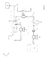
- a fuel system 40 configured to supply fuel F to an energy conversion device 42, such as an advanced diesel engine for example, is illustrated.
- Advanced diesel engines may be used in any number of applications, including, but not limited to, machinery, boats, tractors, generators, and on-road or off-road vehicles for example.
- the fuel system 40 includes a diesel fuel reservoir 44 arranged generally upstream from and operably coupled to the inlet 28 of the deoxygenation system 20 with a first conduit 46.
- the outlet 30 of the deoxygenation system 20 is connected to the energy conversion device 42 by a second conduit 48.
- a pump 50 is configured to draw fuel F from the fuel reservoir 44.
- a strainer 52 and/or at least one filter 54 may be arranged generally downstream from the fuel reservoir 44, such as within conduit 46 for example.
- the strainer 52 and/or filter 54 remove debris particles equal to or greater than a predetermined size from the fuel flow.
- the strainer 52 is configured to remove particles generally larger than a first size
- the one or more filters 54 are configured to remove particles generally larger than a second, smaller size.
- a strainer 52 and/or at least one filter 54 may be arranged generally downstream from the fuel reservoir 44, such as within conduit 46 for example.
- the strainer 52 and/or filter 54 remove debris particles equal to or greater than a predetermined size from the fuel flow.
- the strainer 52 is configured to remove particles generally larger than a first size
- the one or more filters 54 are configured to remove particles generally larger than a second, smaller size.
- the diesel fuel F stored within the fuel reservoir 44 is saturated with dissolved oxygen, for example at a level of approximately 70 ppm.
- the fuel pump 50 communicates with the reservoir 44, such as through a valve (not shown) for example, to supply fuel F to the inlet 28 of the deoxygenation system 20.
- oxygen is removed from the fuel using a vacuum 31 or sweep gas.
- the size and number of fuel channels 22 can be adjusted to remove the desired amount of dissolved oxygen depending on application needs.
- the deoxygenation system 20 is sized for a minimum of 20% deoxygenation to a maximum of 90% deoxygenation, relative to the initial 70 ppm level of dissolved oxygen.
- the deoxygenated fuel F flows through the second conduit 48, from the outlet 30 of the deoxygenation system 20 to the energy conversion device 42, such as the fuel injector of an advance diesel engine.
- the energy conversion device 42 such as the fuel injector of an advance diesel engine.
- a heat exchanger 56 may be positioned generally between the deoxygenation system 20 and the fuel reservoir 44 relative to the flow of fuel F through the system 40.
- the heated medium includes waste heat from another portion of the system, such as the cooling system (not shown) for the energy conversion device 42.
- the cooling system not shown
- Inclusion of the heat exchanger 56 in the fuel system 40 increases the thermodynamic efficiency of the engine, and additionally may reduce the size of the cooling system for the energy conversion device 42.
- the viscosity of the fuel F is reduced such that lower quality diesel fuels may be used.
- the energy conversion device 42 is a marine diesel engine.
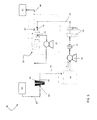
- the fuel system 40 configured for used with the marine diesel engine may additionally include one or more collecting tanks 60 arranged upstream from the fuel reservoir 44.
- a conduit 62 extends from the collecting tank 60 to an inlet 64 of a purifier 66, and another conduit 70 couples the outlet 68 of the purifier 66 to the fuel reservoir 44.
- water such as sea water for example, may also be stored within the collecting tanks 60 to balance the weight of the vessel.
- the fuel F within the collecting tanks 60 may include liquid droplets of sea water as well as some amount of water dissolved within the fuel F.
- the purifier 66 is configured to remove at least a portion of the non-miscible water entrained within the fuel F as the fuel F. After passing through the purifier, water dissolved within the fuel F remains.
- the deoxygenation system 20 includes a membrane 24 permeable to both dissolved water and dissolved oxygen. Therefore, the deoxygenation system 20 works in conjunction with the purifier to limit the amount of non-miscible and dissolved water within the fuel F transferred to the energy conversion device 42.
Landscapes
- Engineering & Computer Science (AREA)
- Chemical & Material Sciences (AREA)
- Combustion & Propulsion (AREA)
- Mechanical Engineering (AREA)
- General Engineering & Computer Science (AREA)
- Physics & Mathematics (AREA)
- Thermal Sciences (AREA)
- Chemical Kinetics & Catalysis (AREA)
- Degasification And Air Bubble Elimination (AREA)
- Separation Using Semi-Permeable Membranes (AREA)
Applications Claiming Priority (1)
| Application Number | Priority Date | Filing Date | Title |
|---|---|---|---|
| US13/851,713 US20140290610A1 (en) | 2013-03-27 | 2013-03-27 | Diesel fuel stabilization for enhanced combustion |
Publications (1)
| Publication Number | Publication Date |
|---|---|
| EP2784299A1 true EP2784299A1 (de) | 2014-10-01 |
Family
ID=50345959
Family Applications (1)
| Application Number | Title | Priority Date | Filing Date |
|---|---|---|---|
| EP14161635.9A Withdrawn EP2784299A1 (de) | 2013-03-27 | 2014-03-26 | Dieselkraftstoffstabilisierung für verbesserte Verbrennung |
Country Status (2)
| Country | Link |
|---|---|
| US (1) | US20140290610A1 (de) |
| EP (1) | EP2784299A1 (de) |
Cited By (3)
| Publication number | Priority date | Publication date | Assignee | Title |
|---|---|---|---|---|
| WO2016135097A1 (de) * | 2015-02-27 | 2016-09-01 | Mann+Hummel Gmbh | Abscheidevorrichtung zur abscheidung wenigstens eines störfluids aus einer flüssigkeit, membran einer abscheidevorrichtung, filter, filterelement und flüssigkeitssystem |
| CN110077605A (zh) * | 2018-01-26 | 2019-08-02 | 哈米尔顿森德斯特兰德公司 | 飞机的油箱催化惰化设备 |
| CN110092002A (zh) * | 2018-01-30 | 2019-08-06 | 哈米尔顿森德斯特兰德公司 | 飞机的油箱催化惰化设备 |
Families Citing this family (2)
| Publication number | Priority date | Publication date | Assignee | Title |
|---|---|---|---|---|
| DE102016222778A1 (de) * | 2016-11-18 | 2018-05-24 | Siemens Aktiengesellschaft | Verfahren zum Entwässern eines Betriebsstoffs, Entwässerungseinrichtung sowie Betriebsstoff-Versorgungseinrichtung |
| US20190022557A1 (en) * | 2017-07-24 | 2019-01-24 | Hamilton Sundstrand Corporation | Fuel tank de-oxygenation system |
Citations (7)
| Publication number | Priority date | Publication date | Assignee | Title |
|---|---|---|---|---|
| US6527603B1 (en) * | 2001-03-07 | 2003-03-04 | Brunswick Corporation | Fuel delivery system for a marine propulsion device |
| EP1559902A1 (de) * | 2004-01-30 | 2005-08-03 | United Technologies Corporation | Verfahren zum Verhindern des Eindringens von Treibstoff in mikroporöse Polymermembranen |
| DE102005000658A1 (de) * | 2005-01-04 | 2006-07-13 | Robert Bosch Gmbh | Kraftstofffilter, insbesondere für Kraftfahrzeuge |
| EP1723996A2 (de) * | 2005-05-18 | 2006-11-22 | United Technologies Corporation | modulare Vorrichtung zur Brennstoffstabilisation |
| EP1810741A2 (de) * | 2006-01-18 | 2007-07-25 | United Technologies Corporation | Brennstoffentgaser mit nicht planarem Brennstoffkanal und sauerstoffdurchlässiger Membran |
| WO2009014799A1 (en) * | 2007-07-26 | 2009-01-29 | General Electric Company | System and method for heating viscous fuel supplied to diesel engines |
| US20100294128A1 (en) * | 2009-05-20 | 2010-11-25 | Schmidt Wayde R | Fuel deoxygenator with porous support plate |
Family Cites Families (5)
| Publication number | Priority date | Publication date | Assignee | Title |
|---|---|---|---|---|
| US6315815B1 (en) * | 1999-12-16 | 2001-11-13 | United Technologies Corporation | Membrane based fuel deoxygenator |
| US6694955B1 (en) * | 2002-07-09 | 2004-02-24 | Brunswick Corporation | Marine engine with primary and secondary fuel reservoirs |
| US6939392B2 (en) * | 2003-04-04 | 2005-09-06 | United Technologies Corporation | System and method for thermal management |
| US7112110B1 (en) * | 2004-09-01 | 2006-09-26 | Brunswick Corporation | Fuel system container for a marine vessel |
| FR2909732B1 (fr) * | 2006-12-12 | 2011-09-23 | Filtrauto | Dispositif de filtration de carburant a deux niveaux |
-
2013
- 2013-03-27 US US13/851,713 patent/US20140290610A1/en not_active Abandoned
-
2014
- 2014-03-26 EP EP14161635.9A patent/EP2784299A1/de not_active Withdrawn
Patent Citations (7)
| Publication number | Priority date | Publication date | Assignee | Title |
|---|---|---|---|---|
| US6527603B1 (en) * | 2001-03-07 | 2003-03-04 | Brunswick Corporation | Fuel delivery system for a marine propulsion device |
| EP1559902A1 (de) * | 2004-01-30 | 2005-08-03 | United Technologies Corporation | Verfahren zum Verhindern des Eindringens von Treibstoff in mikroporöse Polymermembranen |
| DE102005000658A1 (de) * | 2005-01-04 | 2006-07-13 | Robert Bosch Gmbh | Kraftstofffilter, insbesondere für Kraftfahrzeuge |
| EP1723996A2 (de) * | 2005-05-18 | 2006-11-22 | United Technologies Corporation | modulare Vorrichtung zur Brennstoffstabilisation |
| EP1810741A2 (de) * | 2006-01-18 | 2007-07-25 | United Technologies Corporation | Brennstoffentgaser mit nicht planarem Brennstoffkanal und sauerstoffdurchlässiger Membran |
| WO2009014799A1 (en) * | 2007-07-26 | 2009-01-29 | General Electric Company | System and method for heating viscous fuel supplied to diesel engines |
| US20100294128A1 (en) * | 2009-05-20 | 2010-11-25 | Schmidt Wayde R | Fuel deoxygenator with porous support plate |
Cited By (5)
| Publication number | Priority date | Publication date | Assignee | Title |
|---|---|---|---|---|
| WO2016135097A1 (de) * | 2015-02-27 | 2016-09-01 | Mann+Hummel Gmbh | Abscheidevorrichtung zur abscheidung wenigstens eines störfluids aus einer flüssigkeit, membran einer abscheidevorrichtung, filter, filterelement und flüssigkeitssystem |
| CN107250523A (zh) * | 2015-02-27 | 2017-10-13 | 曼·胡默尔有限公司 | 用于从液体中分离出至少一种不期望的流体的分离设备、分离设备的膜、过滤器、过滤元件以及液体系统 |
| US10478780B2 (en) * | 2015-02-27 | 2019-11-19 | Mann+Hummel Gmbh | Separating device for separating at least one undesired fluid from a liquid, membrane of a separating device, filter, filter element, and liquid system |
| CN110077605A (zh) * | 2018-01-26 | 2019-08-02 | 哈米尔顿森德斯特兰德公司 | 飞机的油箱催化惰化设备 |
| CN110092002A (zh) * | 2018-01-30 | 2019-08-06 | 哈米尔顿森德斯特兰德公司 | 飞机的油箱催化惰化设备 |
Also Published As
| Publication number | Publication date |
|---|---|
| US20140290610A1 (en) | 2014-10-02 |
Similar Documents
| Publication | Publication Date | Title |
|---|---|---|
| EP2784299A1 (de) | Dieselkraftstoffstabilisierung für verbesserte Verbrennung | |
| CN102630270B (zh) | 均质化燃料增强系统 | |
| JP6539682B2 (ja) | 内燃機関の窒素酸化物の削減方法及びその装置 | |
| JP2017141837A (ja) | 噴射ポンプを内蔵した液体分離装置 | |
| JP2007190549A (ja) | 燃料システムおよび燃料システム内の溶存酸素の低減方法 | |
| KR890006968A (ko) | 연료 이송 시스템 | |
| US20100155322A1 (en) | Vehicle mounted fuel separation apparatus | |
| EP2883734B1 (de) | Entlüftungsanordnung für Dieselabgasflüssigkeitsbehälter | |
| US9259688B2 (en) | Method for reducing nitrogen oxide from internal combustion engine and apparatus therefor | |
| RU2010139859A (ru) | Система теплообменника | |
| JPWO2014050986A1 (ja) | 内燃機関の運転方法および空気供給装置 | |
| US20190022557A1 (en) | Fuel tank de-oxygenation system | |
| WO2014030242A1 (ja) | 燃焼システム | |
| JP2013522523A (ja) | 燃料供給システム | |
| JP5941224B2 (ja) | 水混合燃料生成装置 | |
| US20200197834A1 (en) | Composite hollow fiber membranes for jet fuel de-oxygenation | |
| US20190022558A1 (en) | Fuel tank de-oxygenation system | |
| JP2007162691A (ja) | 燃料装置、タービンエンジンおよび燃料浄化方法 | |
| EP3550125B1 (de) | Passives kraftstoffadditivdosierungssystem | |
| FR2945080A1 (fr) | Filtre a diffusion d'eau | |
| FI104107B (fi) | Menetelmä ja laite dieselmoottorin pakokaasujen puhdistamiseksi | |
| EP2406546B1 (de) | Abgasreinigungsvorrichtung und verfahren zur abgasreinigung | |
| US10900423B2 (en) | On-board separation process | |
| JP2014221872A (ja) | 水エマルジョン燃料、水エマルジョン燃料供給システム、及び水エマルジョン燃料の供給方法 | |
| DE102008044172A1 (de) | Hydraulisches Aggregat |
Legal Events
| Date | Code | Title | Description |
|---|---|---|---|
| 17P | Request for examination filed |
Effective date: 20140326 |
|
| AK | Designated contracting states |
Kind code of ref document: A1 Designated state(s): AL AT BE BG CH CY CZ DE DK EE ES FI FR GB GR HR HU IE IS IT LI LT LU LV MC MK MT NL NO PL PT RO RS SE SI SK SM TR |
|
| AX | Request for extension of the european patent |
Extension state: BA ME |
|
| PUAI | Public reference made under article 153(3) epc to a published international application that has entered the european phase |
Free format text: ORIGINAL CODE: 0009012 |
|
| STAA | Information on the status of an ep patent application or granted ep patent |
Free format text: STATUS: THE APPLICATION IS DEEMED TO BE WITHDRAWN |
|
| 18D | Application deemed to be withdrawn |
Effective date: 20150402 |