EP2784397A2 - Système de nettoyage pour appareil de cuisine - Google Patents
Système de nettoyage pour appareil de cuisine Download PDFInfo
- Publication number
- EP2784397A2 EP2784397A2 EP14160238.3A EP14160238A EP2784397A2 EP 2784397 A2 EP2784397 A2 EP 2784397A2 EP 14160238 A EP14160238 A EP 14160238A EP 2784397 A2 EP2784397 A2 EP 2784397A2
- Authority
- EP
- European Patent Office
- Prior art keywords
- liquid
- motor
- circulation pump
- cleaning device
- inverter
- Prior art date
- Legal status (The legal status is an assumption and is not a legal conclusion. Google has not performed a legal analysis and makes no representation as to the accuracy of the status listed.)
- Withdrawn
Links
- 238000004140 cleaning Methods 0.000 title claims abstract description 31
- 238000010411 cooking Methods 0.000 claims abstract description 45
- 239000007788 liquid Substances 0.000 claims abstract description 45
- 238000009423 ventilation Methods 0.000 claims abstract description 19
- 238000005086 pumping Methods 0.000 claims abstract description 9
- XLYOFNOQVPJJNP-UHFFFAOYSA-N water Substances O XLYOFNOQVPJJNP-UHFFFAOYSA-N 0.000 claims abstract description 9
- 238000007599 discharging Methods 0.000 claims abstract description 4
- 230000001360 synchronised effect Effects 0.000 claims 1
- 238000009434 installation Methods 0.000 description 7
- 230000008901 benefit Effects 0.000 description 4
- 235000013305 food Nutrition 0.000 description 4
- 239000013505 freshwater Substances 0.000 description 3
- 238000000034 method Methods 0.000 description 3
- 230000008569 process Effects 0.000 description 3
- 239000007787 solid Substances 0.000 description 3
- 239000003925 fat Substances 0.000 description 2
- 230000010354 integration Effects 0.000 description 2
- 230000007246 mechanism Effects 0.000 description 2
- 238000002360 preparation method Methods 0.000 description 2
- 235000008733 Citrus aurantifolia Nutrition 0.000 description 1
- 208000032365 Electromagnetic interference Diseases 0.000 description 1
- 235000011941 Tilia x europaea Nutrition 0.000 description 1
- 238000005352 clarification Methods 0.000 description 1
- 238000009833 condensation Methods 0.000 description 1
- 230000005494 condensation Effects 0.000 description 1
- 238000011109 contamination Methods 0.000 description 1
- 230000007423 decrease Effects 0.000 description 1
- 230000001419 dependent effect Effects 0.000 description 1
- 238000002347 injection Methods 0.000 description 1
- 239000007924 injection Substances 0.000 description 1
- 239000004571 lime Substances 0.000 description 1
- 239000002245 particle Substances 0.000 description 1
- 230000009467 reduction Effects 0.000 description 1
- 239000000126 substance Substances 0.000 description 1
Images

Classifications
-
- F—MECHANICAL ENGINEERING; LIGHTING; HEATING; WEAPONS; BLASTING
- F24—HEATING; RANGES; VENTILATING
- F24C—DOMESTIC STOVES OR RANGES ; DETAILS OF DOMESTIC STOVES OR RANGES, OF GENERAL APPLICATION
- F24C14/00—Stoves or ranges having self-cleaning provisions, e.g. continuous catalytic cleaning or electrostatic cleaning
- F24C14/005—Stoves or ranges having self-cleaning provisions, e.g. continuous catalytic cleaning or electrostatic cleaning using a cleaning liquid
-
- A—HUMAN NECESSITIES
- A21—BAKING; EDIBLE DOUGHS
- A21B—BAKERS' OVENS; MACHINES OR EQUIPMENT FOR BAKING
- A21B3/00—Parts or accessories of ovens
- A21B3/04—Air-treatment devices for ovens, e.g. regulating humidity
-
- A—HUMAN NECESSITIES
- A47—FURNITURE; DOMESTIC ARTICLES OR APPLIANCES; COFFEE MILLS; SPICE MILLS; SUCTION CLEANERS IN GENERAL
- A47L—DOMESTIC WASHING OR CLEANING; SUCTION CLEANERS IN GENERAL
- A47L25/00—Domestic cleaning devices not provided for in other groups of this subclass
-
- F—MECHANICAL ENGINEERING; LIGHTING; HEATING; WEAPONS; BLASTING
- F24—HEATING; RANGES; VENTILATING
- F24C—DOMESTIC STOVES OR RANGES ; DETAILS OF DOMESTIC STOVES OR RANGES, OF GENERAL APPLICATION
- F24C15/00—Details
- F24C15/32—Arrangements of ducts for hot gases, e.g. in or around baking ovens
- F24C15/322—Arrangements of ducts for hot gases, e.g. in or around baking ovens with forced circulation
-
- H—ELECTRICITY
- H02—GENERATION; CONVERSION OR DISTRIBUTION OF ELECTRIC POWER
- H02P—CONTROL OR REGULATION OF ELECTRIC MOTORS, ELECTRIC GENERATORS OR DYNAMO-ELECTRIC CONVERTERS; CONTROLLING TRANSFORMERS, REACTORS OR CHOKE COILS
- H02P5/00—Arrangements specially adapted for regulating or controlling the speed or torque of two or more electric motors
- H02P5/74—Arrangements specially adapted for regulating or controlling the speed or torque of two or more electric motors controlling two or more AC dynamo-electric motors
Definitions
- the invention relates to a cleaning device for kitchen appliances, in particular combi steamers, baking or cooking appliances, with a cooking chamber to be cleaned, which is bounded by at least one wall and on which at least one outlet opening for a liquid is provided with a ventilation wheel, which is associated with the cooking chamber and a drive motor for the ventilation wheel, with a collecting container which at least temporarily receives and collects the liquid emerging from the cooking chamber via the outlet opening, with a supply line connectable to a water reservoir, optionally closable or releasable, via which liquid can be supplied, with a circulating pump Pumping liquid, comprising a Um stiilzpumpenrad and the Ummélzpumpenrad driving Umicalzpumpenmotor, with a circulation line through which the pumped by the circulation pump liquid can be supplied to the cooking chamber to be cleaned, with a at the Sammelbereheat Convenient connected drain line for discharging the liquid received from the collecting container and with a control unit for operating the drive motor and the circulating pump motor.
- the control of the ventilation and pump motors of combi steamers, cooking appliances and similar furnace systems is done separately via separate electronic components.
- power electronics is provided here, which is centrally located on the engine itself.
- the ventilation motor comprises power electronics in which the supply unit with rectifier, intermediate circuit, power factor correction filter on the one hand and the inverter on the other hand are functionally and spatially integrated.
- the object of the invention is to simplify the control of a cooking appliance and to make it inexpensive.
- control device in conjunction with the preamble of claim 1, characterized in that the control device has a decentralized power electronics with a first inverter for the drive motor of the Ventilationsrads and with a second inverter for the circulation pump motor and a common for the inverter and provided a supply network connectable supply unit comprising a rectifier, an intermediate circuit and a power factor correction filter.
- the particular advantage of the invention is that cost benefits result from the use of a common supply unit provided decentrally in relation to the motors and at the same time the space requirement decreases.
- the decentralized placement of the power electronics in total or the supply unit allows operation of the motors at high ambient temperatures, while the supply unit and possibly also the inverters are preferably housed and operated spatially separated in an installation space at a lower ambient temperature. Therefore, less temperature-resistant and cheaper components can be used for this purpose.
- the existing space can be exploited in an optimized manner by the separate arrangement of motors, inverters and supply unit, since a plurality of small components in the space available on the device side is easier to accommodate as a large unit.
- a drain pump is provided with a drain pump impeller and a drain pump motor driving the drain pump impeller.
- the drain pump is used to pump out the liquid emerging from the cooking chamber via the drain line.
- a third inverter for the drain pump motor is provided, wherein the third inverter cooperates with the common supply unit.
- the supply unit feeds all three inverters.
- the drain pump can be controlled inexpensively by using the already provided decentralized power electronics.
- the supply unit of the power electronics with the rectifier, the intermediate circuit and the power factor correction filter serve so far as the supply or control of the ventilation motor, the circulation pump motor and the drain pump motor. This results in a high degree of integration and a reduction of the installation and installation effort.
- the entire power electronics can be designed as a spatial unit and provided away from the motors.
- the inverters are then realized immediately adjacent to the supply unit with the common rectifier, intermediate circuit and power factor correction filter.
- the power electronics provides a decentralized supply unit which feeds the inverters provided in the system for the motors.
- the inverters themselves can be provided spatially adjacent to the motors and fixed, for example, in the region of a bearing plate of the motors. This results in the advantage that the attributable to the motor cables electromagnetic interference can be reduced in the device.
- the power electronics in total or the supply unit can be provided for example on a main control board of the kitchen appliance.
- the main controller for the kitchen appliance is regularly provided or installed at a location where no inadmissibly high or critical temperatures prevail.
- the functional or spatial integration of the power electronics or the supply unit in the main control can be advantageous in terms of space and cost and simplify assembly.
- a central control unit which cooperates with the inverters of the decentralized power electronics.
- the provision of the central control unit ensures that the motors are operated independently of each other and integrated into a uniform overall control process. It is also possible to expand the system modularly when using the central control unit. For example, further actuator components can be controlled by the already provided control unit. Likewise, a heater or sensors may interact with or operate from the central control unit.
- the central control unit can be provided spatially or functionally integrated with the supply unit or the power electronics, for example on the main control board.
- the control topology can in particular provide a data bus for connecting the central control unit to the inverters of the decentralized power electronics. This simplifies the structure of the overall system and it reduces installation costs and costs.
- the data bus will be formed as a serial data bus.
- the speed specification can be realized via the data bus.
- the operated by means of the decentralized power electronics pump motors are coordinated by the central control unit driven.
- the cleaning device provides the collecting container as a common liquid reservoir to which both the drain pump and the Circulation pump are assigned.
- the central control unit is realized in such a way that, for the purpose of cleaning the cooking chamber, liquid is pumped out of the collecting container by means of the circulating pump and supplied to the cooking chamber.
- the pumped liquid can be sprayed onto the rotating ventilation wheel and atomized or distributed.
- the circulation pump and the ventilation motor are operated so far at least temporarily together and simultaneously during the cleaning process.
- the emptying pump can be operated after the cleaning process for pumping out the liquid which has flowed together in the collecting container and the dirt particles, fats and the like contained therein.
- the drain pump motor is in this case operated separately and with a time offset to the circulation pump motor. It is fed by the decentralized power electronics with the common supply unit and the drain pump motor assigned inverter. The control takes place via a central control unit.
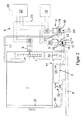
- FIG. 1 shows a cleaning device for a cooking appliance with a cooking chamber 1 to be cleaned, with a arranged in the installed position of the cooking appliance below the cooking chamber 1 collecting container 2, with a to the collecting container.
- 2 provided circulating pump 3 for circulating a liquid stored in the collecting container 2, with a likewise provided on the collecting container 2 drain pump 4 for pumping the water provided in the collecting container 2 via a riser 5 of the cleaning device in a drain line 6 thereof, with a provided on the cooking chamber 1 Ventilation wheel 7, with a drive motor 8 for the ventilation wheel 7 and with a control device for operating the drive motor 8, the circulation pump 3 and the drain pump 4.
- the control device comprises as essential components a distributed power electronics 9 and a central control unit 10.
- the cleaning device is preferred automated self-cleaning of the cooking appliance after use.
- the collected in the collecting container 2 liquids and solids can be promoted by means of the drain pump 4 via the riser 5 in the drain line 6 and transported away.
- the drainage pump 4 is here in a lower region of the collecting container 2 - based on its installation position - provided.
- An emptying pump wheel 12 of the emptying pump 4, which is operated via an emptying pump motor 13, is positioned in a delivery chamber 14 provided on the collecting container 2 as part thereof such that the liquid to be removed enters the delivery chamber 14 via an inlet opening 15.
- On the pressure side is thescentedfördemde Liquid transported via an outlet opening 16 from the pumping chamber 14 in the riser 5 and further into the drain line 6.
- a modern cooking appliance usually has a self-cleaning mechanism.
- the circulation pump 3 and a circulation line 17 are provided. Via the circulation line 17, liquid conveyed by the circulating pump 3 is supplied to the cooking chamber 1 to be cleaned.
- the circulation pump 3, which provides a Umisselzpumpenrad 18 and a circulation pump motor 19 for driving the Umisselzpumpenrads 18 is provided as the drain pump 4 to the collecting container 2.
- the circulation pump 18 is associated with a further delivery chamber 20, wherein the delivery chamber 14 is realized as part of the collecting container 2.
- the liquid to be circulated is conveyed through an outlet opening 22 into the recirculation line 17 and from there fed to the cooking chamber 1.
- the control unit 10 of the control device is designed as a central control unit 10. It communicates via a serial data bus 23 with three inverters 24, 25, 26.
- the inverters 24, 25, 26 are implemented as part of the power electronics 9 and feed the drive motor 8 of the ventilation wheel 7, the circulation pump motor 19 and the drain pump motor 13. Further includes the Power electronics 9, a common supply unit 27, which feeds the inverters 24, 25, 26 and includes a rectifier, an intermediate circuit and a power factor correction filter (PFC).
- the supply unit 27 is connected via a supply line 28 to a supply network (not shown).
- the supply unit 27 is implemented as a network input unit. It is operated on a mains voltage and supplies the connected inverters 24, 25, 26 with the intended intermediate circuit voltage.
- the inverters 24, 25, 26 are provided directly adjacent to the supply unit 27 of the power electronics 9 decentralized and remote from the motors 8, 13, 19.
- the inverters 24, 25, 26 are connected to the motors 8, 13, 19 via motor lines 29, 30, 31.
- the central control unit 10 controls the inverters 24, 25, 26 of the drive motor 8, the evacuation pump motor 13 and the circulation pump motor 19 via the data bus 23 separately and as needed so that the drive motor 8 are operated independently of the pumps 3, 4 during the preparation of food can. Also, during the self-cleaning, the circulation pump 3 and optionally the drive motor 8 can be controlled as needed and separately. Furthermore, it is possible to operate the emptying pump 4 for discharging the liquid provided in the collecting container 2, for example, after the self-cleaning has been carried out independently of the other motors 8, 19.
- the decentralized arrangement of the power electronics 9 allows the operation of the motors 8, 13, 19 at high ambient temperatures of for example up to 70 ° C by the supply unit 27 and possibly also the inverters 24, 25, 26 are provided in a cool installation space of the cooking appliance.
- the supply unit 27 for the three inverters 24, 25, 26 synergies are also developed and reduced costs.
- the provision of inverter-controlled pump motors 13, 19 allows the variable-speed operation of these motors 13, 19 and increases the efficiency of the entire system.
- the pump motors 13, 19 are implemented as so-called BLDC motors or brushless DC motors.
- the inverters 24, 25, 26 of the power electronics 9 are arranged distributed.
- the first inverter 24, which is provided for the variable-speed drive of the drive motor 8, is provided directly on the drive motor 8 of the ventilation wheel 7.
- the inverter 24 may be fixed to a bearing plate of the drive motor 8.
- the second inverter 25 is provided to the drain pump motor 13 and the third inverter 26 to the circulation pump motor 19. Again, the determination of the inverter 25, 26 in the region of a bearing plate of the motors 13, 19 done.
- the decentralized supply unit 27 of the power electronics 9 feeds the inverters 24, 25, 26 and supplies them with the required intermediate circuit voltage.
- the supply unit 27 is in a cooler installation space housed the cooking appliance.
- the serial data bus 23 connects the central control unit 10 and the inverters 24, 25, 26.
- the provision of the inverters 24, 25, 26 on the motors 8, 13, 19 reduces the electromagnetic interferences, which in particular from the motor lines 29, 30, 31 can go out.
- the invention has been illustrated using the example of a cooking appliance or a cleaning device for a cooking appliance.
- the cleaning device can also be realized for other kitchen appliances, in particular for combi steamers, baking appliances or similar oven systems.
- the kitchen appliances can be designed as commercially used kitchen appliances or as household kitchen appliances.
- Both embodiments of the invention provide a sensor 32 for detecting a quantity of liquid provided in the collecting container 2 at the collecting container 2.
- the sensor 32 may be formed, for example, in the manner of a pressure sensor.
- the sensor 32 may communicate with the central control unit 10, for example via the serial data bus 23 provided anyway.
- the provision of the pressure sensor 32 is optional in this case.
- a temperature sensor or a sensor for determining a degree of contamination of the liquid provided in the collecting container 2 can be provided.
- a supply line 33 connected to an unrepresented water reservoir can be provided at the collecting container 2, via which, for example, fresh water or a cleaning liquid is supplied to the collecting container 2.
- a valve 34 can be provided on this.
- the supply line 33 may be connected to the cooking chamber 1 such that fresh water is introduced via the supply line 33 directly into the cooking chamber 1. Unchanged, the valve 34 may be provided are used to influence a supplied via the supply line 33 amount of fresh water.
- an overflow 35 can be provided, via which liquid provided in the collecting container 2 is directly supplied to the discharge line 6, as soon as a maximum permissible liquid level in the collecting container 2 is exceeded.
- a drain 36 can be provided for liquid to be discharged from the cooking chamber 1, via which at least part of the liquid passes directly to the drain line 6, bypassing the collecting container 2.
- Such a drain 36 is realized, for example, in the region of a door 37 of the cooking appliance.
- the inverter 24 is provided for the motor 8 directly to the drive motor 8, while the inverters 25, 26 are installed for the pump motors 13, 19 together with the supply unit 27 remote from the location of the motors 13, 19.
Landscapes
- Engineering & Computer Science (AREA)
- Chemical & Material Sciences (AREA)
- Combustion & Propulsion (AREA)
- Mechanical Engineering (AREA)
- General Engineering & Computer Science (AREA)
- Chemical Kinetics & Catalysis (AREA)
- Food Science & Technology (AREA)
- Life Sciences & Earth Sciences (AREA)
- Power Engineering (AREA)
- Cookers (AREA)
- Cleaning By Liquid Or Steam (AREA)
- Food-Manufacturing Devices (AREA)
- Washing And Drying Of Tableware (AREA)
Applications Claiming Priority (2)
| Application Number | Priority Date | Filing Date | Title |
|---|---|---|---|
| DE102013004660 | 2013-03-19 | ||
| DE102013110975.6A DE102013110975B4 (de) | 2013-03-19 | 2013-10-02 | Ansteuerung für ein Gargerät |
Publications (2)
| Publication Number | Publication Date |
|---|---|
| EP2784397A2 true EP2784397A2 (fr) | 2014-10-01 |
| EP2784397A3 EP2784397A3 (fr) | 2016-03-09 |
Family
ID=50280264
Family Applications (1)
| Application Number | Title | Priority Date | Filing Date |
|---|---|---|---|
| EP14160238.3A Withdrawn EP2784397A3 (fr) | 2013-03-19 | 2014-03-17 | Système de nettoyage pour appareil de cuisine |
Country Status (3)
| Country | Link |
|---|---|
| US (1) | US20140366921A1 (fr) |
| EP (1) | EP2784397A3 (fr) |
| DE (1) | DE102013110975B4 (fr) |
Cited By (1)
| Publication number | Priority date | Publication date | Assignee | Title |
|---|---|---|---|---|
| EP4397909A4 (fr) * | 2021-08-31 | 2024-12-18 | Panasonic Intellectual Property Management Co., Ltd. | Appareil de cuisson chauffant |
Families Citing this family (1)
| Publication number | Priority date | Publication date | Assignee | Title |
|---|---|---|---|---|
| DE102022119502B4 (de) * | 2022-08-03 | 2025-06-05 | Welbilt Deutschland GmbH | Gargerät |
Family Cites Families (6)
| Publication number | Priority date | Publication date | Assignee | Title |
|---|---|---|---|---|
| DE19809558C2 (de) * | 1998-03-05 | 2001-02-22 | Bsh Bosch Siemens Hausgeraete | Elektroherd mit Steuereinheit und Netzanschlußklemme |
| ES2287836T3 (es) * | 2005-04-29 | 2007-12-16 | MKN MASCHINENFABRIK KURT NEUBAUER GMBH & CO. | Aparato de cocinado con una salida del recinto de cocinado y un sifon. |
| DE202006003349U1 (de) * | 2006-03-01 | 2007-07-12 | Sinnotec Entwicklungsgesellschaft Ltd. | Reinigungssystem mit von außerhalb des Gerätes durch die Gerätetropfwanne einbringbaren Reinigungsmitteln |
| DE102007060975A1 (de) * | 2007-12-14 | 2009-06-25 | Hanning Elektro-Werke Gmbh & Co. Kg | Antrieb |
| WO2012163313A1 (fr) * | 2011-06-01 | 2012-12-06 | Hanning Elektro-Werke Gmbh & Co. Kg | Dispositif d'alimentation électrique de consommateurs électriques |
| US9677769B2 (en) * | 2012-02-02 | 2017-06-13 | Convotherm Elektrogeraete Gmbh | Flexible sequence control and method for automated cleaning system of a cooking device |
-
2013
- 2013-10-02 DE DE102013110975.6A patent/DE102013110975B4/de active Active
-
2014
- 2014-03-17 EP EP14160238.3A patent/EP2784397A3/fr not_active Withdrawn
- 2014-03-19 US US14/219,750 patent/US20140366921A1/en not_active Abandoned
Non-Patent Citations (1)
| Title |
|---|
| None |
Cited By (1)
| Publication number | Priority date | Publication date | Assignee | Title |
|---|---|---|---|---|
| EP4397909A4 (fr) * | 2021-08-31 | 2024-12-18 | Panasonic Intellectual Property Management Co., Ltd. | Appareil de cuisson chauffant |
Also Published As
| Publication number | Publication date |
|---|---|
| DE102013110975B4 (de) | 2015-11-05 |
| US20140366921A1 (en) | 2014-12-18 |
| EP2784397A3 (fr) | 2016-03-09 |
| DE102013110975A1 (de) | 2014-09-25 |
Similar Documents
| Publication | Publication Date | Title |
|---|---|---|
| EP2781839B2 (fr) | Appareil de cuisson comportant un dispositif de nettoyage | |
| DE102012025591B4 (de) | Verfahren zum Betreiben eines Geschirrspülers mit geschlossenem Kondenserkreis | |
| DE102014001944B4 (de) | Geschirrspülmaschine und Steuerverfahren derselben | |
| DE69409916T2 (de) | Dampfsteuereinrichtung eines Backofens | |
| EP3190344B1 (fr) | Appareil de cuisson | |
| DE102015104470B4 (de) | Kochfeld sowie ein Verfahren zum Betreiben eines Kochfeldes | |
| DE2739198A1 (de) | Geraet zum garen bzw. erhitzen von esswaren | |
| WO2017162680A1 (fr) | Appareil de cuisson commercial | |
| DE102007005502A1 (de) | Verfahren zur Reinigung eines Gargeräts und Gargerät hierfür | |
| DE102016201243A1 (de) | Grillofen mit Schießrohr-Reinigungssystem | |
| DE102007004599B4 (de) | Hauben-Geschirrspülmaschine mit Kondensatniederschlagseinrichtung | |
| DE19509569A1 (de) | Ofen zur Wärmebehandlung von Lebensmitteln und Verfahren zum Backen | |
| EP1355560B1 (fr) | Lave-vaisselle industriel | |
| WO2010100149A2 (fr) | Combinaison d'appareils de cuisson | |
| DE102013110975B4 (de) | Ansteuerung für ein Gargerät | |
| EP2462808B1 (fr) | Appareil de cuisson à vapeur | |
| EP3759397A1 (fr) | Ventilateur de table et procédé servant à nettoyer un ventilateur de table | |
| EP2353486A2 (fr) | Module de séchage pour un lave-vaisselle | |
| EP2605661B2 (fr) | Appareil de cuisson à la vapeur | |
| EP3172371B1 (fr) | Appareil ménager équipé d'un système de transvasement à pompe | |
| EP0687434B1 (fr) | Four de cuisson pour cuisson à vapeur | |
| DE102007030573B4 (de) | Gargerät mit zumindest einer Kondensationseinrichtung und Verfahren zum Entfeuchten eines Garraums solch eines Gargeräts | |
| BE1030516B1 (de) | Gareinrichtung und Verfahren zum Betreiben | |
| DE102015114006B4 (de) | Backofenreinigungssystem und -verfahren | |
| DE202013012917U1 (de) | Reinigungsvorrichtung für Küchengeräte und Pumpensystem |
Legal Events
| Date | Code | Title | Description |
|---|---|---|---|
| 17P | Request for examination filed |
Effective date: 20140317 |
|
| AK | Designated contracting states |
Kind code of ref document: A2 Designated state(s): AL AT BE BG CH CY CZ DE DK EE ES FI FR GB GR HR HU IE IS IT LI LT LU LV MC MK MT NL NO PL PT RO RS SE SI SK SM TR |
|
| AX | Request for extension of the european patent |
Extension state: BA ME |
|
| PUAI | Public reference made under article 153(3) epc to a published international application that has entered the european phase |
Free format text: ORIGINAL CODE: 0009012 |
|
| PUAL | Search report despatched |
Free format text: ORIGINAL CODE: 0009013 |
|
| AK | Designated contracting states |
Kind code of ref document: A3 Designated state(s): AL AT BE BG CH CY CZ DE DK EE ES FI FR GB GR HR HU IE IS IT LI LT LU LV MC MK MT NL NO PL PT RO RS SE SI SK SM TR |
|
| AX | Request for extension of the european patent |
Extension state: BA ME |
|
| RIC1 | Information provided on ipc code assigned before grant |
Ipc: F24C 15/32 20060101ALI20160204BHEP Ipc: H02P 31/00 20060101ALI20160204BHEP Ipc: A21B 3/04 20060101ALI20160204BHEP Ipc: F24C 14/00 20060101AFI20160204BHEP |
|
| R17P | Request for examination filed (corrected) |
Effective date: 20160829 |
|
| RBV | Designated contracting states (corrected) |
Designated state(s): AL AT BE BG CH CY CZ DE DK EE ES FI FR GB GR HR HU IE IS IT LI LT LU LV MC MK MT NL NO PL PT RO RS SE SI SK SM TR |
|
| STAA | Information on the status of an ep patent application or granted ep patent |
Free format text: STATUS: EXAMINATION IS IN PROGRESS |
|
| 17Q | First examination report despatched |
Effective date: 20180724 |
|
| STAA | Information on the status of an ep patent application or granted ep patent |
Free format text: STATUS: THE APPLICATION IS DEEMED TO BE WITHDRAWN |
|
| 18D | Application deemed to be withdrawn |
Effective date: 20190205 |