EP2784429B1 - Dispositif caloporteur et four équipé de celui-ci - Google Patents
Dispositif caloporteur et four équipé de celui-ci Download PDFInfo
- Publication number
- EP2784429B1 EP2784429B1 EP14000881.4A EP14000881A EP2784429B1 EP 2784429 B1 EP2784429 B1 EP 2784429B1 EP 14000881 A EP14000881 A EP 14000881A EP 2784429 B1 EP2784429 B1 EP 2784429B1
- Authority
- EP
- European Patent Office
- Prior art keywords
- heat
- transfer device
- heat transfer
- ducts
- heat absorber
- Prior art date
- Legal status (The legal status is an assumption and is not a legal conclusion. Google has not performed a legal analysis and makes no representation as to the accuracy of the status listed.)
- Active
Links
Images



Classifications
-
- F—MECHANICAL ENGINEERING; LIGHTING; HEATING; WEAPONS; BLASTING
- F28—HEAT EXCHANGE IN GENERAL
- F28D—HEAT-EXCHANGE APPARATUS, NOT PROVIDED FOR IN ANOTHER SUBCLASS, IN WHICH THE HEAT-EXCHANGE MEDIA DO NOT COME INTO DIRECT CONTACT
- F28D21/00—Heat-exchange apparatus not covered by any of the groups F28D1/00 - F28D20/00
- F28D21/0001—Recuperative heat exchangers
- F28D21/0003—Recuperative heat exchangers the heat being recuperated from exhaust gases
- F28D21/0005—Recuperative heat exchangers the heat being recuperated from exhaust gases for domestic or space-heating systems
- F28D21/0007—Water heaters
-
- F—MECHANICAL ENGINEERING; LIGHTING; HEATING; WEAPONS; BLASTING
- F24—HEATING; RANGES; VENTILATING
- F24B—DOMESTIC STOVES OR RANGES FOR SOLID FUELS; IMPLEMENTS FOR USE IN CONNECTION WITH STOVES OR RANGES
- F24B9/00—Stoves, ranges or flue-gas ducts, with additional provisions for heating water
- F24B9/006—Stoves, ranges or flue-gas ducts, with additional provisions for heating water flue-gas ducts
-
- F—MECHANICAL ENGINEERING; LIGHTING; HEATING; WEAPONS; BLASTING
- F24—HEATING; RANGES; VENTILATING
- F24C—DOMESTIC STOVES OR RANGES ; DETAILS OF DOMESTIC STOVES OR RANGES, OF GENERAL APPLICATION
- F24C15/00—Details
- F24C15/34—Elements and arrangements for heat storage or insulation
-
- F—MECHANICAL ENGINEERING; LIGHTING; HEATING; WEAPONS; BLASTING
- F24—HEATING; RANGES; VENTILATING
- F24H—FLUID HEATERS, e.g. WATER OR AIR HEATERS, HAVING HEAT-GENERATING MEANS, e.g. HEAT PUMPS, IN GENERAL
- F24H9/00—Details
- F24H9/0005—Details for water heaters
- F24H9/001—Guiding means
- F24H9/0026—Guiding means in combustion gas channels
-
- F—MECHANICAL ENGINEERING; LIGHTING; HEATING; WEAPONS; BLASTING
- F28—HEAT EXCHANGE IN GENERAL
- F28F—DETAILS OF HEAT-EXCHANGE AND HEAT-TRANSFER APPARATUS, OF GENERAL APPLICATION
- F28F13/00—Arrangements for modifying heat-transfer, e.g. increasing, decreasing
- F28F13/06—Arrangements for modifying heat-transfer, e.g. increasing, decreasing by affecting the pattern of flow of the heat-exchange media
- F28F13/08—Arrangements for modifying heat-transfer, e.g. increasing, decreasing by affecting the pattern of flow of the heat-exchange media by varying the cross-section of the flow channels
-
- F—MECHANICAL ENGINEERING; LIGHTING; HEATING; WEAPONS; BLASTING
- F28—HEAT EXCHANGE IN GENERAL
- F28F—DETAILS OF HEAT-EXCHANGE AND HEAT-TRANSFER APPARATUS, OF GENERAL APPLICATION
- F28F27/00—Control arrangements or safety devices specially adapted for heat-exchange or heat-transfer apparatus
-
- F—MECHANICAL ENGINEERING; LIGHTING; HEATING; WEAPONS; BLASTING
- F28—HEAT EXCHANGE IN GENERAL
- F28F—DETAILS OF HEAT-EXCHANGE AND HEAT-TRANSFER APPARATUS, OF GENERAL APPLICATION
- F28F9/00—Casings; Header boxes; Auxiliary supports for elements; Auxiliary members within casings
- F28F9/22—Arrangements for directing heat-exchange media into successive compartments, e.g. arrangements of guide plates
-
- F—MECHANICAL ENGINEERING; LIGHTING; HEATING; WEAPONS; BLASTING
- F28—HEAT EXCHANGE IN GENERAL
- F28G—CLEANING OF INTERNAL OR EXTERNAL SURFACES OF HEAT-EXCHANGE OR HEAT-TRANSFER CONDUITS, e.g. WATER TUBES OR BOILERS
- F28G1/00—Non-rotary, e.g. reciprocated, appliances
-
- F—MECHANICAL ENGINEERING; LIGHTING; HEATING; WEAPONS; BLASTING
- F24—HEATING; RANGES; VENTILATING
- F24H—FLUID HEATERS, e.g. WATER OR AIR HEATERS, HAVING HEAT-GENERATING MEANS, e.g. HEAT PUMPS, IN GENERAL
- F24H2230/00—Solid fuel fired boiler
Definitions
- the invention relates to a heat transfer device, comprising a gas inlet for a heat-containing gas, at least one pulling channel, which is flowed through by the gas, a heat absorber, which receives heat emitted by the flowing gas, and a gas outlet for the thus cooled gas, as well as a oven equipped with such a heat transfer device.
- Such heat transfer devices are well known in the art. They serve to deliver the heat contained in the flue gas of the furnace, which has a temperature of about 900 °, not unused to the environment, but to withdraw the flue gas before to use them selectively.
- the flue gas is usually cooled to temperatures below 200 °, even up to about 120 ° or 110 °.
- the heat absorbers receiving the heat removed from the gas can be designed as classic heat exchangers, in which a circulating fluid near the draw channel flows past and absorbs heat, which it otherwise, for example in radiators, again gives off.
- the heat can also be stored by the heat absorber (so-called fireclay masses). It is said to store the heat in bulk. The stored heat is then released over a longer period of time to the environment.
- the invention is based on the finding that a Buchkanal arrangement differently than vertically upwardly extending channels with symmetrical, d. H. Circular or square / rectangular cross-section (i.e., without excellent side) improves the flow conduction and uniformity of heat transfer. Under the predominant heat emission to the one excellent side is to be understood with respect to the outer boundary of the Werkanals clearly asymmetrical to this one side displaced heat flow.
- the shape and / or attitude property causes a shift in the weight of the flow distribution orthogonal to the flow direction of the flowing gas toward the side of the heat absorber.
- a corresponding outer excellent boundary surface of the Glaskanals be formed by the inner surface of the heat absorber. The main heat transfer takes place via this excellent site.
- the invention provides several shape and location properties that contribute to this desired asymmetric heat transfer.
- a further positional property according to the invention provides for a narrowing of the cross section of the pulling channel. This ensures a more uniform heat transfer, in particular with regard to the height direction.
- the boundary which confines the heat absorber, opposite boundary is inclined in the same direction from the vertical, for producing the taper but at a lower angle of inclination, preferably in the range between 20% and 80%, preferably between 30% and 70 %, in particular between 40% and 60% of the angle of inclination of the heat absorber side is.
- inclination angles of 2 ° or more, but also 4 ° or more are preferred, with preferred upper limits of 24 °, more preferably 16 °, in particular 8 °.
- a particularly preferred embodiment provides for the simultaneous realization of the tapering cross-sectional shape with asymmetrical flow resistance in the case of an inclined boundary of the pulling channel facing the heat receiver.
- a shape characteristic refers to the shape of the cross-sectional area of the pulling channel. On the one hand, this preferably has a region of the boundary opposite the boundary facing the heat absorber, the shape of which generates an increased flow resistance with respect to the other side. This shifts the flow weight in turn further to the excellent boundary side to the heat absorber.
- a preferred cross-sectional constriction preferably only one transverse dimension of the Buchkanals shortens, while the other remains unchanged. The shape of the cross section of the Werkanals thus changes over the height, but not their basic shape.
- the shape of a right triangle with the hypotenuse formed by the heat receiver would lose the right-angled shape and change to an obtuse-angled triangle.
- the corresponding transverse dimension is reduced to half.
- the heat transfer device has a plurality of such pull channels, which are in particular divided into two groups and form a right and a left part of a Glaskanal Modell. These are constructed, for example, axially symmetrical to a center plane of the furnace, wherein the heat absorber is also divided into two and each extending on the outside of the two halves of the Glaskanal Modell. To the inside, the two halves of the Werkanalstructure are limited by the respective plurality of Werkanälen by insulating material, the latter can be realized for example in the form of a particular hanging insert that forms the area of the boundary of the Werkanäle that do not correspond to the excellent side to the heat absorber.
- the heat transfer device has a mechanism with which the cross-sectional area of the sum of the Werkanäle is variable within certain limits, in particular feasible by the type of suspension of the insert, which defines the remaining part of the boundaries of the Werkanäle.
- a cleaning device in particular for cleaning the inner surfaces of the heat absorbers.
- This is also preferably achieved by the type of suspension of the insert, which allows a suitably actuated pendulum movement of the insert.
- the invention also provides a furnace equipped with such a heat transfer device under protection.
- the gas inlet of the heat transfer device is connected to a flue gas outlet of the combustion chamber, so that the flue gas can flow through the draft channels of the heat transfer device.
- the advantages of the furnace according to the invention result from the above-described advantages of the heat transfer device according to the invention and in particular relate to a particularly uniform heat transfer over the entire surface of the heat absorber with very good efficiencies.
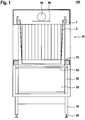
- the in Fig. 1 illustrated furnace 100 has a supported on legs 30 combustion chamber 20 which is accessible via a provided with a handle 60 door 50 for operators of the furnace 100.
- the legs 30 are based on, for example, height-adjustable feet 40.
- a flange plate 70 is arranged, which has a central opening 71 for the withdrawal of the combustion chamber 20 during operation resulting flue gas.
- the oven 100 has features known in the art.
- the structure of the heat transfer device 10 will be described in more detail.
- Fig. 2 It can be seen that the heat transfer device 10 in this embodiment, the furnace front side facing and remote heat absorber 8 has. These extend into Fig. 2 perpendicular to the plane of the paper over substantially the full width of the furnace 100 between two structural side parts, not shown, of the heat transfer device 10.
- Fig. 3 is a bottom view of the heat transfer device 10, in the center of the carrier 5 and laterally outside the heat receivers 8 are shown.
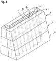
- Each side 6L and 6R of the pull channel structure 6L, 6R has a plurality of pull channels 3 bounded on its outside by the inner surface 7 of the heat absorber 8.
- a pulling channel 3 is bounded by two along the edge 4c an angle with each other enclosing side surfaces 4a, 4b, so that the pulling channel 3 in a horizontal section assumes a triangular shape in this embodiment. Since the edge 4c connecting the two side surfaces 4a, 4b does not have the same inclination ⁇ as the inner surface 7 of the heat absorber 8, the cross section of the pulling channel 3 tapers with increasing height.
- the edge 4c is also inclined inwardly, but by an angle ⁇ , which in this embodiment is about 4 °, ie about half of the angle ⁇ .
- the course of the edge 4c thus turns in the height direction of the height direction corresponding to the natural slope direction of the flue gas. This also contributes to the fact that the flow weight shifts toward the inner surface 7 of the heat absorber 8.
- due to the reduced in cross-section cross-section of the Werkanals 3 with the height increasing speed of the flue gas due to the uniform heat transfer is achieved in the heat absorber 8 despite the fact that the flue gas continues to cool down on its flow path.
- the area around the edge 4c which is predetermined by the geometry of the side surfaces 4a, 4b, furthermore forms a zone of higher flow resistance which further shifts the main flow and thus the main heat transfer in the direction of the inner surface 7 of the heat absorber 8.
- this leads to a special asymmetric heat transfer in the pulling channel 3, on one side towards the outside, ie to the inner surface 7 of the heat absorber 8.
- the heat absorber 8 is configured as a heat storage, and for example by a fireclay material (burned fireclay, pressed refractory bricks, soapstone, etc.) is formed, which is able to absorb larger amounts of heat and slowly return to the environment.
- a fireclay material burned fireclay, pressed refractory bricks, soapstone, etc.
- the material of the insert 4 is a barely absorbing heat insulating material, which also hardly sooty.
- the side parts (not shown in the figures) are fastened on the flange plate 70 and attach to the rear side (page 6R) a part of the heat absorber 8, for example in the form of ribs to be inserted as explained above.
- the carrier 5 is suspended, which is held laterally by two end portions 2, which are loaded on train.
- the latter are mounted on setscrews 1 ( Fig. 1 ), which in turn can be suitably supported on the heat absorber 8.
- the inner insert 4 is thus a hinged structure.
- the forming parts of the insert 4 can be installed. These may be provided, for example, in sentences that define, for example, two or three of the draft channels 3. Optionally, longer pieces defining more than three pull channels could be made in one piece. Subsequently, the installation of the other part of the heat absorber 8 on the other side (to page 6L) take place. Finally, the heat transfer device 10 is surrounded by a housing, not shown, which is arranged in any case in the case of an embodiment of the heat absorber 8 as a heat storage spaced therefrom.
- the insert 4 Due to the substantially point-shaped mounting of the end portions 2 on the screws 1, the insert 4 has a total of a movement in a in Fig. 2 perpendicular to the paper plane direction, so the oven width direction.
- a back and forth of the insert 4 in the oven width direction can be performed for example by an unillustrated actuator by hand, which can be realized for example by a push rod with direct power transmission or via a transmission.
- the edges 4d scrape between a face 4a of the insert and its side face 4b of an adjacent pulling channel 3 (see FIG Fig. 3 ) on the inner surface 7 of the heat absorber 8 along and scratch off soot deposits. These fall down into a reachable via the door 50 area of the combustion chamber 20 and can thus be easily removed.
- the heat transfer device 10 also allows very simple cleaning options. Ideally, the distance between two consecutive outer edges 4d is smaller than the clearance for this movement in the direction of movement.
- Fig. 3 The cross-sectional shape of the Buchkanäle 3 is not on in Fig. 3 shown triangular shape restricted.
- other cross-sectional geometries could also be used, some of which are still preferred, for example Fig. 5 are shown, namely trapezoidal, semicircular (or more generally schkegelintroducingförmig).
Landscapes
- Engineering & Computer Science (AREA)
- Mechanical Engineering (AREA)
- General Engineering & Computer Science (AREA)
- Chemical & Material Sciences (AREA)
- Combustion & Propulsion (AREA)
- Physics & Mathematics (AREA)
- Thermal Sciences (AREA)
- Heat-Exchange Devices With Radiators And Conduit Assemblies (AREA)
Claims (12)
- Dispositif caloporteur (10) destiné notamment à être raccordé en aval d'un four et comportant une entrée de gaz (3u) pour un gaz contenant de la chaleur,
au moins un canal de tirage (3) qui présente une section transversale allant en diminuant dans le sens de l'écoulement et qui est traversé par le gaz,
un absorbeur de chaleur (8) qui absorbe la chaleur dégagée par le gaz en écoulement, et
une sortie de gaz destinée au gaz ainsi refroidi ;
ledit absorbeur de chaleur (8) étant disposé sur un côté extérieur (7) de l'au moins un canal de tirage (3),
caractérisé en ce que le dégagement de chaleur se produit majoritairement en direction du côté de l'absorbeur de chaleur en raison d'une propriété positionnelle de l'au moins un canal de tirage (3), ladite propriété positionnelle étant assurée, d'une part, par l'inclinaison d'une délimitation extérieure (7) de l'au moins un canal de tirage vers le côté de l'absorbeur de chaleur (8), à savoir en s'éloignant de l'absorbeur de chaleur (8) vu par rapport à la verticale dans le sens de l'écoulement, et d'autre part par une moindre inclinaison, en comparaison de cette inclinaison, d'une délimitation dudit canal de tirage (3) opposée à ladite délimitation extérieure (7), ledit canal de tirage présentant une zone de délimitation (4c) définie, vue en coupe, par sa distance maximale à la délimitation (7) tournée vers l'absorbeur de chaleur, là encore en s'éloignant de l'absorbeur de chaleur (8) vu par rapport à la verticale dans le sens de l'écoulement. - Dispositif caloporteur selon la revendication 1, dans lequel la propriété positionnelle et/ou une propriété de forme de l'au moins un canal de tirage (3) entraîne un décalage du poids de la répartition du flux orthogonalement au sens de l'écoulement du gaz en écoulement, vers le côté (7) de l'absorbeur de chaleur.
- Dispositif caloporteur selon l'une des revendications précédentes, dans lequel une zone de l'au moins un canal de tirage, qui est opposée à la délimitation (7) tournée vers l'absorbeur de chaleur (8), présente une propriété de forme consistant en une résistance accrue à l'écoulement.
- Dispositif caloporteur selon l'une des revendications précédentes, dans lequel le canal de tirage (3) présente une propriété de forme consistant en le fait que la forme de la section transversale de l'au moins un canal de tirage (3) est polygonale, notamment triangulaire ou en trapézoïdale, ou semi-circulaire ou ellipsoïdale.
- Dispositif caloporteur selon l'une des revendications précédentes, dans lequel l'absorbeur de chaleur présente au moins deux zones (8, 8) spatialement séparées l'une de l'autre.
- Dispositif caloporteur selon la revendication 5, dans lequel une structure de canal de tirage (6L, 6R) présentant l'au moins un canal de tirage (3) est disposée dans l'espace intermédiaire séparant les au moins deux zones (8, 8) de l'absorbeur de chaleur.
- Dispositif caloporteur selon la revendication 6, dans lequel la structure de canal de tirage (6L, 6R) présente au moins deux parties, et chacune de ces parties (6L, 6R) présente au moins un canal de tirage.
- Dispositif caloporteur selon l'une des revendications précédentes, dans lequel une/la structure de canal de tirage (6L, 6R) présente une pluralité de canaux de tirage (3), et dans lequel notamment chaque partie de la structure de canal de tirage présente plusieurs canaux de tirage.
- Dispositif caloporteur selon l'une des revendications précédentes comportant un insert (4) définissant au moins en partie la géométrie de la délimitation restante (4a, 4b) de l'au moins un canal de tirage qui n'est pas tournée vers l'absorbeur de chaleur, ledit insert (4) étant notamment situé dans une zone centrale et étant notamment maintenu suspendu.
- Dispositif caloporteur selon l'une des revendications précédentes, comportant un mécanisme de réglage (2, 1) destiné au réglage de la taille de la section transversale de l'au moins un canal de tirage (3), notamment de tous les canaux de tirage, ledit mécanisme de réglage (1, 2) reposant notamment sur une aptitude à faire varier la hauteur selon laquelle est suspendu l'insert (4).
- Dispositif caloporteur selon l'une des revendications précédentes, comportant un mécanisme de nettoyage (1, 2 ; 4d), servant notamment à nettoyer la délimitation de l'au moins un canal de tirage qui est tournée vers l'absorbeur de chaleur, ledit mécanisme de nettoyage (1, 2; 4d) reposant notamment sur un montage de l'insert (4) permettant un mouvement pendulaire celui-ci.
- Four (100) comportant une chambre de combustion (20) et un dispositif caloporteur (10) selon l'une des revendications précédentes, dont l'entrée de gaz (3u) est reliée à une sortie de gaz de combustion (71) de la chambre de combustion (20).
Applications Claiming Priority (1)
| Application Number | Priority Date | Filing Date | Title |
|---|---|---|---|
| DE102013004370.0A DE102013004370A1 (de) | 2013-03-12 | 2013-03-12 | Wärmeübertragungsvorrichtung und damit ausgestatteter Ofen |
Publications (3)
| Publication Number | Publication Date |
|---|---|
| EP2784429A2 EP2784429A2 (fr) | 2014-10-01 |
| EP2784429A3 EP2784429A3 (fr) | 2015-04-01 |
| EP2784429B1 true EP2784429B1 (fr) | 2019-05-08 |
Family
ID=50280114
Family Applications (1)
| Application Number | Title | Priority Date | Filing Date |
|---|---|---|---|
| EP14000881.4A Active EP2784429B1 (fr) | 2013-03-12 | 2014-03-12 | Dispositif caloporteur et four équipé de celui-ci |
Country Status (2)
| Country | Link |
|---|---|
| EP (1) | EP2784429B1 (fr) |
| DE (1) | DE102013004370A1 (fr) |
Family Cites Families (14)
| Publication number | Priority date | Publication date | Assignee | Title |
|---|---|---|---|---|
| BE382428A (fr) * | ||||
| FR596112A (fr) * | 1924-03-24 | 1925-10-16 | Dispositif de transmission de chaleur ou de froid à des gaz ou un liquide renfermés dans un réservoir | |
| CH109666A (de) * | 1924-07-30 | 1925-04-16 | Stettler Hans | Vorrichtung zur Ausnützung der in den Abgasen von Zimmeröfen, Kochherden usw. enthaltenen Wärme. |
| CH170375A (de) * | 1933-08-23 | 1934-07-15 | Keller Wiggenhauser Gottlieb | Einrichtung zur besseren Wärmeausnützung der Verbrennungsgase von Heizungsöfen. |
| CH224915A (de) * | 1942-03-14 | 1942-12-31 | Loew & Co | Einrichtung zur Flüssigkeitserhitzung mit einem als Aufsatz an Herden usw. ausgebildeten Wasserbehälter. |
| US2557712A (en) * | 1947-10-20 | 1951-06-19 | Wenger Edgar | Water heater |
| ES349259A1 (es) * | 1967-01-04 | 1969-04-01 | Hourwitz | Perfeccionamientos en los intercambiadores termicos de gas-liquido. |
| DE3708386A1 (de) * | 1987-03-14 | 1988-09-22 | Hans Peter Wittrock | Rekuperator |
| AT7216U1 (de) * | 2003-09-26 | 2004-11-25 | Johann Perhofer | Wärmetauscher zur rückgewinnung der wärme von abgas |
| US7000572B1 (en) * | 2004-10-02 | 2006-02-21 | Schimmeyer Werner K | Telescopic baffle for water heater |
| DE202006000391U1 (de) | 2006-01-11 | 2006-03-02 | Rainer, Johann | Reinigungsvorrichtung |
| DE102006019057A1 (de) * | 2006-04-25 | 2007-10-31 | Johann Rainer | Ofen mit Primärzuluft und Verfahren zum Betreiben eines solchen Ofens |
| DE102008002096A1 (de) * | 2008-05-30 | 2009-12-03 | Robert Bosch Gmbh | Wärmeübertrager |
| AT507528B1 (de) * | 2008-10-09 | 2013-01-15 | Kalkgruber Johann | Wärmetauscher für einen heizkessel |
-
2013
- 2013-03-12 DE DE102013004370.0A patent/DE102013004370A1/de not_active Withdrawn
-
2014
- 2014-03-12 EP EP14000881.4A patent/EP2784429B1/fr active Active
Non-Patent Citations (1)
| Title |
|---|
| None * |
Also Published As
| Publication number | Publication date |
|---|---|
| EP2784429A2 (fr) | 2014-10-01 |
| EP2784429A3 (fr) | 2015-04-01 |
| DE102013004370A1 (de) | 2014-09-18 |
Similar Documents
| Publication | Publication Date | Title |
|---|---|---|
| EP3225139A1 (fr) | Dispositif d'evaporation pour l'eau | |
| EP2765364A1 (fr) | Mémoire en couches | |
| DE102013204069B4 (de) | Lüfterzarge und Lüftermodul für einen Kühler eines Kraftfahrzeugs | |
| EP3327366A1 (fr) | Sortie d'air permettant le reglage de la temperature d'une chambre | |
| EP2784429B1 (fr) | Dispositif caloporteur et four équipé de celui-ci | |
| AT519899B1 (de) | Kühldeckenelement | |
| DE3702272C2 (fr) | ||
| EP1146210A2 (fr) | Système de refroidissement en forme de caisson pour véhicule automobile | |
| AT514842B1 (de) | Vorrichtung und Verfahren zum Zwischenspeichern thermischer Energie | |
| DE102017204492A1 (de) | Wärmetauscher für eine Schmelzflusselektrolysezelle | |
| EP3450654B1 (fr) | Composant à refroidissement automatique | |
| DE202011050181U1 (de) | Heizmodul und Heizkörpervorrichtung | |
| DE944192C (de) | Mit Hilfsgas arbeitender Absorptionskaelteapparat | |
| EP3161402B1 (fr) | Échangeur thermique | |
| DE1257175B (de) | Siedekuehlvorrichtung | |
| DE102016116977B3 (de) | Flüssigkeitstank mit einer Heizeinrichtung | |
| DE102014208254A1 (de) | Latentwärmespeicher | |
| EP3339734B1 (fr) | Chambre de combustion à petite échelle et élément vibrant pour une chambre de combustion à petite échelle | |
| EP4382806A1 (fr) | Radiateur de chauffage alimenté par biomasse | |
| DE1454295A1 (de) | Raumheizgeraet fuer Kleinraeume,insbesondere Wohnwaegen | |
| WO2016102046A1 (fr) | Dispositif de guidage pour contrôler l'écoulement de liquide dans le cadre de l'alimentation en flux biphasiques d'échangeurs de chaleur de type noyau-enveloppe | |
| WO2014111452A1 (fr) | Sortie d'air pour le conditionnement de l'air ambiant dans une pièce, et procédé afférent | |
| DE102015101048B3 (de) | Heizkessel | |
| DE1237251B (de) | Brenneranlage fuer pulsierende Verbrennung | |
| DE2624617B2 (de) | Brenner mit Wärmetauscher |
Legal Events
| Date | Code | Title | Description |
|---|---|---|---|
| 17P | Request for examination filed |
Effective date: 20140312 |
|
| AK | Designated contracting states |
Kind code of ref document: A2 Designated state(s): AL AT BE BG CH CY CZ DE DK EE ES FI FR GB GR HR HU IE IS IT LI LT LU LV MC MK MT NL NO PL PT RO RS SE SI SK SM TR |
|
| AX | Request for extension of the european patent |
Extension state: BA ME |
|
| PUAI | Public reference made under article 153(3) epc to a published international application that has entered the european phase |
Free format text: ORIGINAL CODE: 0009012 |
|
| PUAL | Search report despatched |
Free format text: ORIGINAL CODE: 0009013 |
|
| AK | Designated contracting states |
Kind code of ref document: A3 Designated state(s): AL AT BE BG CH CY CZ DE DK EE ES FI FR GB GR HR HU IE IS IT LI LT LU LV MC MK MT NL NO PL PT RO RS SE SI SK SM TR |
|
| AX | Request for extension of the european patent |
Extension state: BA ME |
|
| RIC1 | Information provided on ipc code assigned before grant |
Ipc: F28G 1/00 20060101ALI20150224BHEP Ipc: F28F 9/22 20060101AFI20150224BHEP Ipc: F24H 9/00 20060101ALI20150224BHEP Ipc: F28F 13/08 20060101ALI20150224BHEP Ipc: F24B 9/00 20060101ALI20150224BHEP Ipc: F28F 27/00 20060101ALI20150224BHEP |
|
| R17P | Request for examination filed (corrected) |
Effective date: 20151001 |
|
| RBV | Designated contracting states (corrected) |
Designated state(s): AL AT BE BG CH CY CZ DE DK EE ES FI FR GB GR HR HU IE IS IT LI LT LU LV MC MK MT NL NO PL PT RO RS SE SI SK SM TR |
|
| REG | Reference to a national code |
Ref country code: DE Ref legal event code: R079 Ref document number: 502014011627 Country of ref document: DE Free format text: PREVIOUS MAIN CLASS: F28F0009220000 Ipc: F24B0009000000 |
|
| GRAP | Despatch of communication of intention to grant a patent |
Free format text: ORIGINAL CODE: EPIDOSNIGR1 |
|
| STAA | Information on the status of an ep patent application or granted ep patent |
Free format text: STATUS: GRANT OF PATENT IS INTENDED |
|
| RIC1 | Information provided on ipc code assigned before grant |
Ipc: F24B 9/00 20060101AFI20181106BHEP Ipc: F28F 9/22 20060101ALI20181106BHEP Ipc: F28F 13/08 20060101ALI20181106BHEP Ipc: F24H 9/00 20060101ALI20181106BHEP Ipc: F24C 15/34 20060101ALI20181106BHEP Ipc: F28F 27/00 20060101ALI20181106BHEP Ipc: F28G 1/00 20060101ALI20181106BHEP |
|
| INTG | Intention to grant announced |
Effective date: 20181206 |
|
| GRAS | Grant fee paid |
Free format text: ORIGINAL CODE: EPIDOSNIGR3 |
|
| GRAA | (expected) grant |
Free format text: ORIGINAL CODE: 0009210 |
|
| STAA | Information on the status of an ep patent application or granted ep patent |
Free format text: STATUS: THE PATENT HAS BEEN GRANTED |
|
| AK | Designated contracting states |
Kind code of ref document: B1 Designated state(s): AL AT BE BG CH CY CZ DE DK EE ES FI FR GB GR HR HU IE IS IT LI LT LU LV MC MK MT NL NO PL PT RO RS SE SI SK SM TR |
|
| REG | Reference to a national code |
Ref country code: GB Ref legal event code: FG4D Free format text: NOT ENGLISH |
|
| REG | Reference to a national code |
Ref country code: CH Ref legal event code: EP Ref country code: AT Ref legal event code: REF Ref document number: 1130745 Country of ref document: AT Kind code of ref document: T Effective date: 20190515 |
|
| REG | Reference to a national code |
Ref country code: DE Ref legal event code: R096 Ref document number: 502014011627 Country of ref document: DE |
|
| REG | Reference to a national code |
Ref country code: IE Ref legal event code: FG4D Free format text: LANGUAGE OF EP DOCUMENT: GERMAN |
|
| REG | Reference to a national code |
Ref country code: CH Ref legal event code: NV Representative=s name: WERNER FENNER PATENTANWALT, CH |
|
| REG | Reference to a national code |
Ref country code: NL Ref legal event code: MP Effective date: 20190508 |
|
| REG | Reference to a national code |
Ref country code: LT Ref legal event code: MG4D |
|
| PG25 | Lapsed in a contracting state [announced via postgrant information from national office to epo] |
Ref country code: NO Free format text: LAPSE BECAUSE OF FAILURE TO SUBMIT A TRANSLATION OF THE DESCRIPTION OR TO PAY THE FEE WITHIN THE PRESCRIBED TIME-LIMIT Effective date: 20190808 Ref country code: PT Free format text: LAPSE BECAUSE OF FAILURE TO SUBMIT A TRANSLATION OF THE DESCRIPTION OR TO PAY THE FEE WITHIN THE PRESCRIBED TIME-LIMIT Effective date: 20190908 Ref country code: FI Free format text: LAPSE BECAUSE OF FAILURE TO SUBMIT A TRANSLATION OF THE DESCRIPTION OR TO PAY THE FEE WITHIN THE PRESCRIBED TIME-LIMIT Effective date: 20190508 Ref country code: SE Free format text: LAPSE BECAUSE OF FAILURE TO SUBMIT A TRANSLATION OF THE DESCRIPTION OR TO PAY THE FEE WITHIN THE PRESCRIBED TIME-LIMIT Effective date: 20190508 Ref country code: AL Free format text: LAPSE BECAUSE OF FAILURE TO SUBMIT A TRANSLATION OF THE DESCRIPTION OR TO PAY THE FEE WITHIN THE PRESCRIBED TIME-LIMIT Effective date: 20190508 Ref country code: LT Free format text: LAPSE BECAUSE OF FAILURE TO SUBMIT A TRANSLATION OF THE DESCRIPTION OR TO PAY THE FEE WITHIN THE PRESCRIBED TIME-LIMIT Effective date: 20190508 Ref country code: HR Free format text: LAPSE BECAUSE OF FAILURE TO SUBMIT A TRANSLATION OF THE DESCRIPTION OR TO PAY THE FEE WITHIN THE PRESCRIBED TIME-LIMIT Effective date: 20190508 Ref country code: ES Free format text: LAPSE BECAUSE OF FAILURE TO SUBMIT A TRANSLATION OF THE DESCRIPTION OR TO PAY THE FEE WITHIN THE PRESCRIBED TIME-LIMIT Effective date: 20190508 Ref country code: NL Free format text: LAPSE BECAUSE OF FAILURE TO SUBMIT A TRANSLATION OF THE DESCRIPTION OR TO PAY THE FEE WITHIN THE PRESCRIBED TIME-LIMIT Effective date: 20190508 |
|
| PG25 | Lapsed in a contracting state [announced via postgrant information from national office to epo] |
Ref country code: LV Free format text: LAPSE BECAUSE OF FAILURE TO SUBMIT A TRANSLATION OF THE DESCRIPTION OR TO PAY THE FEE WITHIN THE PRESCRIBED TIME-LIMIT Effective date: 20190508 Ref country code: RS Free format text: LAPSE BECAUSE OF FAILURE TO SUBMIT A TRANSLATION OF THE DESCRIPTION OR TO PAY THE FEE WITHIN THE PRESCRIBED TIME-LIMIT Effective date: 20190508 Ref country code: GR Free format text: LAPSE BECAUSE OF FAILURE TO SUBMIT A TRANSLATION OF THE DESCRIPTION OR TO PAY THE FEE WITHIN THE PRESCRIBED TIME-LIMIT Effective date: 20190809 Ref country code: BG Free format text: LAPSE BECAUSE OF FAILURE TO SUBMIT A TRANSLATION OF THE DESCRIPTION OR TO PAY THE FEE WITHIN THE PRESCRIBED TIME-LIMIT Effective date: 20190808 |
|
| PG25 | Lapsed in a contracting state [announced via postgrant information from national office to epo] |
Ref country code: CZ Free format text: LAPSE BECAUSE OF FAILURE TO SUBMIT A TRANSLATION OF THE DESCRIPTION OR TO PAY THE FEE WITHIN THE PRESCRIBED TIME-LIMIT Effective date: 20190508 Ref country code: RO Free format text: LAPSE BECAUSE OF FAILURE TO SUBMIT A TRANSLATION OF THE DESCRIPTION OR TO PAY THE FEE WITHIN THE PRESCRIBED TIME-LIMIT Effective date: 20190508 Ref country code: SK Free format text: LAPSE BECAUSE OF FAILURE TO SUBMIT A TRANSLATION OF THE DESCRIPTION OR TO PAY THE FEE WITHIN THE PRESCRIBED TIME-LIMIT Effective date: 20190508 Ref country code: DK Free format text: LAPSE BECAUSE OF FAILURE TO SUBMIT A TRANSLATION OF THE DESCRIPTION OR TO PAY THE FEE WITHIN THE PRESCRIBED TIME-LIMIT Effective date: 20190508 Ref country code: EE Free format text: LAPSE BECAUSE OF FAILURE TO SUBMIT A TRANSLATION OF THE DESCRIPTION OR TO PAY THE FEE WITHIN THE PRESCRIBED TIME-LIMIT Effective date: 20190508 |
|
| REG | Reference to a national code |
Ref country code: DE Ref legal event code: R097 Ref document number: 502014011627 Country of ref document: DE |
|
| PG25 | Lapsed in a contracting state [announced via postgrant information from national office to epo] |
Ref country code: SM Free format text: LAPSE BECAUSE OF FAILURE TO SUBMIT A TRANSLATION OF THE DESCRIPTION OR TO PAY THE FEE WITHIN THE PRESCRIBED TIME-LIMIT Effective date: 20190508 |
|
| PLBE | No opposition filed within time limit |
Free format text: ORIGINAL CODE: 0009261 |
|
| STAA | Information on the status of an ep patent application or granted ep patent |
Free format text: STATUS: NO OPPOSITION FILED WITHIN TIME LIMIT |
|
| PG25 | Lapsed in a contracting state [announced via postgrant information from national office to epo] |
Ref country code: TR Free format text: LAPSE BECAUSE OF FAILURE TO SUBMIT A TRANSLATION OF THE DESCRIPTION OR TO PAY THE FEE WITHIN THE PRESCRIBED TIME-LIMIT Effective date: 20190508 |
|
| 26N | No opposition filed |
Effective date: 20200211 |
|
| PG25 | Lapsed in a contracting state [announced via postgrant information from national office to epo] |
Ref country code: PL Free format text: LAPSE BECAUSE OF FAILURE TO SUBMIT A TRANSLATION OF THE DESCRIPTION OR TO PAY THE FEE WITHIN THE PRESCRIBED TIME-LIMIT Effective date: 20190508 |
|
| PG25 | Lapsed in a contracting state [announced via postgrant information from national office to epo] |
Ref country code: SI Free format text: LAPSE BECAUSE OF FAILURE TO SUBMIT A TRANSLATION OF THE DESCRIPTION OR TO PAY THE FEE WITHIN THE PRESCRIBED TIME-LIMIT Effective date: 20190508 |
|
| PG25 | Lapsed in a contracting state [announced via postgrant information from national office to epo] |
Ref country code: MC Free format text: LAPSE BECAUSE OF FAILURE TO SUBMIT A TRANSLATION OF THE DESCRIPTION OR TO PAY THE FEE WITHIN THE PRESCRIBED TIME-LIMIT Effective date: 20190508 |
|
| REG | Reference to a national code |
Ref country code: BE Ref legal event code: MM Effective date: 20200331 |
|
| PG25 | Lapsed in a contracting state [announced via postgrant information from national office to epo] |
Ref country code: LU Free format text: LAPSE BECAUSE OF NON-PAYMENT OF DUE FEES Effective date: 20200312 |
|
| PG25 | Lapsed in a contracting state [announced via postgrant information from national office to epo] |
Ref country code: IE Free format text: LAPSE BECAUSE OF NON-PAYMENT OF DUE FEES Effective date: 20200312 |
|
| REG | Reference to a national code |
Ref country code: CH Ref legal event code: NV Representative=s name: SERAINA FENNER, CH |
|
| PG25 | Lapsed in a contracting state [announced via postgrant information from national office to epo] |
Ref country code: BE Free format text: LAPSE BECAUSE OF NON-PAYMENT OF DUE FEES Effective date: 20200331 |
|
| GBPC | Gb: european patent ceased through non-payment of renewal fee |
Effective date: 20200312 |
|
| PG25 | Lapsed in a contracting state [announced via postgrant information from national office to epo] |
Ref country code: GB Free format text: LAPSE BECAUSE OF NON-PAYMENT OF DUE FEES Effective date: 20200312 |
|
| PG25 | Lapsed in a contracting state [announced via postgrant information from national office to epo] |
Ref country code: MT Free format text: LAPSE BECAUSE OF FAILURE TO SUBMIT A TRANSLATION OF THE DESCRIPTION OR TO PAY THE FEE WITHIN THE PRESCRIBED TIME-LIMIT Effective date: 20190508 Ref country code: CY Free format text: LAPSE BECAUSE OF FAILURE TO SUBMIT A TRANSLATION OF THE DESCRIPTION OR TO PAY THE FEE WITHIN THE PRESCRIBED TIME-LIMIT Effective date: 20190508 |
|
| PG25 | Lapsed in a contracting state [announced via postgrant information from national office to epo] |
Ref country code: MK Free format text: LAPSE BECAUSE OF FAILURE TO SUBMIT A TRANSLATION OF THE DESCRIPTION OR TO PAY THE FEE WITHIN THE PRESCRIBED TIME-LIMIT Effective date: 20190508 Ref country code: IS Free format text: LAPSE BECAUSE OF FAILURE TO SUBMIT A TRANSLATION OF THE DESCRIPTION OR TO PAY THE FEE WITHIN THE PRESCRIBED TIME-LIMIT Effective date: 20190908 |
|
| PGFP | Annual fee paid to national office [announced via postgrant information from national office to epo] |
Ref country code: IT Payment date: 20240327 Year of fee payment: 11 Ref country code: FR Payment date: 20240315 Year of fee payment: 11 |
|
| PGFP | Annual fee paid to national office [announced via postgrant information from national office to epo] |
Ref country code: CH Payment date: 20240611 Year of fee payment: 11 |
|
| PGFP | Annual fee paid to national office [announced via postgrant information from national office to epo] |
Ref country code: DE Payment date: 20250324 Year of fee payment: 12 |
|
| PGFP | Annual fee paid to national office [announced via postgrant information from national office to epo] |
Ref country code: AT Payment date: 20250326 Year of fee payment: 12 |
|
| REG | Reference to a national code |
Ref country code: CH Ref legal event code: H13 Free format text: ST27 STATUS EVENT CODE: U-0-0-H10-H13 (AS PROVIDED BY THE NATIONAL OFFICE) Effective date: 20251023 |
|
| PG25 | Lapsed in a contracting state [announced via postgrant information from national office to epo] |
Ref country code: FR Free format text: LAPSE BECAUSE OF NON-PAYMENT OF DUE FEES Effective date: 20250331 Ref country code: IT Free format text: LAPSE BECAUSE OF NON-PAYMENT OF DUE FEES Effective date: 20250312 |
|
| PG25 | Lapsed in a contracting state [announced via postgrant information from national office to epo] |
Ref country code: CH Free format text: LAPSE BECAUSE OF NON-PAYMENT OF DUE FEES Effective date: 20250331 |