EP2784609A2 - Steuersystem für fahrbare Maschine und Antriebssteuereinheit - Google Patents
Steuersystem für fahrbare Maschine und Antriebssteuereinheit Download PDFInfo
- Publication number
- EP2784609A2 EP2784609A2 EP14161074.1A EP14161074A EP2784609A2 EP 2784609 A2 EP2784609 A2 EP 2784609A2 EP 14161074 A EP14161074 A EP 14161074A EP 2784609 A2 EP2784609 A2 EP 2784609A2
- Authority
- EP
- European Patent Office
- Prior art keywords
- control unit
- driving
- control
- ridable
- sensor signal
- Prior art date
- Legal status (The legal status is an assumption and is not a legal conclusion. Google has not performed a legal analysis and makes no representation as to the accuracy of the status listed.)
- Withdrawn
Links
Images


Classifications
-
- B—PERFORMING OPERATIONS; TRANSPORTING
- B60—VEHICLES IN GENERAL
- B60L—PROPULSION OF ELECTRICALLY-PROPELLED VEHICLES; SUPPLYING ELECTRIC POWER FOR AUXILIARY EQUIPMENT OF ELECTRICALLY-PROPELLED VEHICLES; ELECTRODYNAMIC BRAKE SYSTEMS FOR VEHICLES IN GENERAL; MAGNETIC SUSPENSION OR LEVITATION FOR VEHICLES; MONITORING OPERATING VARIABLES OF ELECTRICALLY-PROPELLED VEHICLES; ELECTRIC SAFETY DEVICES FOR ELECTRICALLY-PROPELLED VEHICLES
- B60L3/00—Electric devices on electrically-propelled vehicles for safety purposes; Monitoring operating variables, e.g. speed, deceleration or energy consumption
- B60L3/0023—Detecting, eliminating, remedying or compensating for drive train abnormalities, e.g. failures within the drive train
- B60L3/0046—Detecting, eliminating, remedying or compensating for drive train abnormalities, e.g. failures within the drive train relating to electric energy storage systems, e.g. batteries or capacitors
-
- B—PERFORMING OPERATIONS; TRANSPORTING
- B60—VEHICLES IN GENERAL
- B60L—PROPULSION OF ELECTRICALLY-PROPELLED VEHICLES; SUPPLYING ELECTRIC POWER FOR AUXILIARY EQUIPMENT OF ELECTRICALLY-PROPELLED VEHICLES; ELECTRODYNAMIC BRAKE SYSTEMS FOR VEHICLES IN GENERAL; MAGNETIC SUSPENSION OR LEVITATION FOR VEHICLES; MONITORING OPERATING VARIABLES OF ELECTRICALLY-PROPELLED VEHICLES; ELECTRIC SAFETY DEVICES FOR ELECTRICALLY-PROPELLED VEHICLES
- B60L3/00—Electric devices on electrically-propelled vehicles for safety purposes; Monitoring operating variables, e.g. speed, deceleration or energy consumption
- B60L3/0023—Detecting, eliminating, remedying or compensating for drive train abnormalities, e.g. failures within the drive train
- B60L3/0084—Detecting, eliminating, remedying or compensating for drive train abnormalities, e.g. failures within the drive train relating to control modules
-
- B—PERFORMING OPERATIONS; TRANSPORTING
- B60—VEHICLES IN GENERAL
- B60L—PROPULSION OF ELECTRICALLY-PROPELLED VEHICLES; SUPPLYING ELECTRIC POWER FOR AUXILIARY EQUIPMENT OF ELECTRICALLY-PROPELLED VEHICLES; ELECTRODYNAMIC BRAKE SYSTEMS FOR VEHICLES IN GENERAL; MAGNETIC SUSPENSION OR LEVITATION FOR VEHICLES; MONITORING OPERATING VARIABLES OF ELECTRICALLY-PROPELLED VEHICLES; ELECTRIC SAFETY DEVICES FOR ELECTRICALLY-PROPELLED VEHICLES
- B60L3/00—Electric devices on electrically-propelled vehicles for safety purposes; Monitoring operating variables, e.g. speed, deceleration or energy consumption
- B60L3/0092—Electric devices on electrically-propelled vehicles for safety purposes; Monitoring operating variables, e.g. speed, deceleration or energy consumption with use of redundant elements for safety purposes
-
- B—PERFORMING OPERATIONS; TRANSPORTING
- B60—VEHICLES IN GENERAL
- B60L—PROPULSION OF ELECTRICALLY-PROPELLED VEHICLES; SUPPLYING ELECTRIC POWER FOR AUXILIARY EQUIPMENT OF ELECTRICALLY-PROPELLED VEHICLES; ELECTRODYNAMIC BRAKE SYSTEMS FOR VEHICLES IN GENERAL; MAGNETIC SUSPENSION OR LEVITATION FOR VEHICLES; MONITORING OPERATING VARIABLES OF ELECTRICALLY-PROPELLED VEHICLES; ELECTRIC SAFETY DEVICES FOR ELECTRICALLY-PROPELLED VEHICLES
- B60L58/00—Methods or circuit arrangements for monitoring or controlling batteries or fuel cells, specially adapted for electric vehicles
- B60L58/10—Methods or circuit arrangements for monitoring or controlling batteries or fuel cells, specially adapted for electric vehicles for monitoring or controlling batteries
-
- B—PERFORMING OPERATIONS; TRANSPORTING
- B60—VEHICLES IN GENERAL
- B60L—PROPULSION OF ELECTRICALLY-PROPELLED VEHICLES; SUPPLYING ELECTRIC POWER FOR AUXILIARY EQUIPMENT OF ELECTRICALLY-PROPELLED VEHICLES; ELECTRODYNAMIC BRAKE SYSTEMS FOR VEHICLES IN GENERAL; MAGNETIC SUSPENSION OR LEVITATION FOR VEHICLES; MONITORING OPERATING VARIABLES OF ELECTRICALLY-PROPELLED VEHICLES; ELECTRIC SAFETY DEVICES FOR ELECTRICALLY-PROPELLED VEHICLES
- B60L2250/00—Driver interactions
- B60L2250/26—Driver interactions by pedal actuation
-
- Y—GENERAL TAGGING OF NEW TECHNOLOGICAL DEVELOPMENTS; GENERAL TAGGING OF CROSS-SECTIONAL TECHNOLOGIES SPANNING OVER SEVERAL SECTIONS OF THE IPC; TECHNICAL SUBJECTS COVERED BY FORMER USPC CROSS-REFERENCE ART COLLECTIONS [XRACs] AND DIGESTS
- Y02—TECHNOLOGIES OR APPLICATIONS FOR MITIGATION OR ADAPTATION AGAINST CLIMATE CHANGE
- Y02T—CLIMATE CHANGE MITIGATION TECHNOLOGIES RELATED TO TRANSPORTATION
- Y02T10/00—Road transport of goods or passengers
- Y02T10/60—Other road transportation technologies with climate change mitigation effect
- Y02T10/70—Energy storage systems for electromobility, e.g. batteries
-
- Y—GENERAL TAGGING OF NEW TECHNOLOGICAL DEVELOPMENTS; GENERAL TAGGING OF CROSS-SECTIONAL TECHNOLOGIES SPANNING OVER SEVERAL SECTIONS OF THE IPC; TECHNICAL SUBJECTS COVERED BY FORMER USPC CROSS-REFERENCE ART COLLECTIONS [XRACs] AND DIGESTS
- Y02—TECHNOLOGIES OR APPLICATIONS FOR MITIGATION OR ADAPTATION AGAINST CLIMATE CHANGE
- Y02T—CLIMATE CHANGE MITIGATION TECHNOLOGIES RELATED TO TRANSPORTATION
- Y02T10/00—Road transport of goods or passengers
- Y02T10/60—Other road transportation technologies with climate change mitigation effect
- Y02T10/72—Electric energy management in electromobility
Definitions
- the embodiments discussed herein are related to a control system for a ridable machine and a driving control unit.
- JP 4-150701 A As an example of a technology of securing reliability against errors in control devices of an electric automobile, there is a technology disclosed in JP 4-150701 A .
- the technology disclosed in JP 4-150701 A provides a vehicle which drives right and left tires independently using a plurality of motors, in which a control of gradually stopping the motors is performed while making the speeds of the motors synchronous to each other by using microprocessors oriented to the right and left motors in response to a trouble of a microprocessor oriented to the vehicle.
- An object of the invention is to make possible a refuge travel of a ridable machine into a safe zone, even when an error occurs in a control system for the ridable machine.
- a control system for a ridable machine may include a driving control unit configured to control a driving source of a ridable machine, and an operation control unit configured to control the driving control unit according to an operation signal of the ridable machine.
- the respective control units mutually monitor an operation state of each other, and when a first control unit of the control units detects an error of the other (second) control unit, the first control unit performs a driving control on the driving source at a speed more limited than that in a normal mode based on the operation signal.
- FIG. 1 is a block diagram illustrating an example of a vehicle control system according to an embodiment.
- a vehicle control system 1 illustrated in FIG. 1 is used in a next-generation electric automobile (that is an example of ridable machines) such as an electric vehicle (EV) and a hybrid electric vehicle (HEV).
- the vehicle control system 1 for example, is provided with an accelerator sensor 10, a brake sensor 20, a vehicle control unit (VCU) 30, a motor control unit (MCU) 40, a motor train module (MTM) 50, a motor 60, a lithium-ion battery (LiB) unit 70, an ignition (IG) voltage source 80, and an IG switch 90.
- VCU vehicle control unit
- MCU motor control unit
- MTM motor train module
- IG lithium-ion battery
- IG ignition
- the accelerator sensor 10 is operable to sense information (for example, voltage information) of an accelerator opening degree (stepping amount) of a vehicle and transmit the obtained information to the VCU 30 as an accelerator sensor signal.
- the brake sensor 20 is operable to sense information (for example, voltage information) of a brake stepping amount of the vehicle and transmit the obtained information to the VCU 30 as a brake sensor signal.
- information for example, voltage information
- the accelerator sensor 10 and the brake sensor 20 operates with power supplied from the VCU 30 in a normal mode.
- the accelerator sensor signal and the brake sensor signal are examples of operation signals of the vehicle.
- the respective sensor signals obtained by the accelerator sensor 10 and the brake sensor 20 are also input to the MCU 40 in addition to the VCU 30 for a case where an error occurs in the VCU 30 as described later (see Reference Numeral 100 of FIG. 1 ).
- the VCU 30 is an example of an operation control unit operable to control the travelling of the vehicle by transmitting a travelling control signal such as a torque command value to the MCU 40 based on the accelerator sensor signal and the brake sensor signal obtained by the accelerator sensor 10 and the brake sensor 20, respectively.
- the VCU 30 is operable to calculate a travelling torque and give a regeneration command based on the accelerator sensor signal, calculate the amount of regeneration energy, give a command, and control drivability based on the brake sensor signal.
- the travelling control signal for example, may be generated by a microcomputer or the like built in the VCU 30.
- the VCU 30 is provided with an accelerator sensor power source 301 which supplies power to the accelerator sensor 10 and a brake sensor power source 302 which supplies power to the brake sensor 20. Furthermore, the VCU 30 is provided with a function of monitoring a battery voltage (VDC) which is supplied to the MTM 50 from the LiB unit 70.
- VDC battery voltage
- the VDC for example, is measured by the MTM 50 which is supplied with power from the LiB unit 70, and sent to the VCU 30 through the MCU 40.
- Reference Numeral 303 represents a mutual monitor
- Reference Numeral 304 represents a reset signal receiver.
- the mutual monitor 303 and the reset signal receiver 304 will be described later.
- the MCU 40 is an example of a driving control unit operable to control a driving force of the motor 60 by controlling a driving power supplied from the MTM 50 to the motor 60 according to the travelling control signal received from the VCU 30.
- the MCU 40 performs a feedback control on the motor 60 based on the torque command value and the sensor signals of an angle sensor (a resolver) and a current sensor provided for the motor 60 so that the torque of the motor 60 is matched with the torque command value commanded from the VCU 30.
- the MTM 50 receives a power voltage (or a battery voltage) from the LiB unit 70, generates a driving voltage (for example, DC 200 V to 300 V) for the motor 60 according to the driving power controlled from the MCU 40, and supplies the driving power of three-phase AC power to the motor 60.
- a driving voltage for example, DC 200 V to 300 V
- the MTM 50 is provided with an inverter (not illustrated) including IGBTs and the like, and uses the inverter to generate the driving power for the motor 60.
- the motor 60 is an example of a driving source of the vehicle, for example, a three-phase synchronous motor.
- the motor 60 is provided with the resolver and the current sensor described above. Further, some types of the motor 60 may be built in the MTM 50.
- the LiB unit 70 is operable to supply the power voltage (the battery voltage) to the MTM 50.
- the LiB unit 70 for example, is configured by connecting a plurality of battery cells in series or parallel. An operation of inputting voltage, current, and temperature of the LiB unit 70, a control for safety, a control of balancing voltages among the battery cells, an operation of calculating a used energy amount and a remaining battery capacity, an operation of estimating a degradation state, and the like are performed by a battery control unit (BCU) which is not illustrated in FIG. 1 .
- BCU battery control unit
- the IG voltage source 80 supplies a power voltage (for example, 12V) common to the VCU 30 and the MCU 40.
- a power voltage for example, 12V
- the VCU 30 is activated, and then an activating command is given from the VCU 30 to the MCU 40 through a communication interface such as a serial-to-parallel interface (SPI), thereby the MCU 40 is activated.
- SPI serial-to-parallel interface
- the MCU 40 is provided with a mutual monitor 401, a reset signal generator 402, a sensor power source 403, a sensor power source switch 404, and a refuge travelling mode controller (hereinafter, may be referred to as a "safe mode controller") 405. Further, the meaning of the "safe mode" will be described below.
- the mutual monitor 401 is, for example, operable to periodically transceive a predetermined signal with respect to the VCU 30 through a communication interface such as the SPI (see Reference Numeral 400 of FIG. 1 ) to monitor whether the VCU 30 is in error or not.
- the VCU 30 and the MCU 40 transmit a pulse train (for example, a sawtooth counter signal in FIG. 2 ), which has a predetermined amplitude (for example, a count number in a range of 0 to 255), to each other from the mutual monitors 303 and 401.
- a pulse train for example, a sawtooth counter signal in FIG. 2
- a predetermined amplitude for example, a count number in a range of 0 to 255
- the MCU 40 or the VCU 30, which determines that an error occurs in the other, is operable to transmit a reset signal (a stop control signal) to the other party from the reset signal generator 402 or 305 (see FIG. 2 ) which is an example of a stop control signal transmitter.
- the reset signal is received by a reset signal receiver 304 in the VCU 30 and is received by a reset signal receiver 406 in the MCU 40.
- the VCU 30 or the MCU 40 which has received the reset signal stops its operation.
- the VCU 30 shuts down the accelerator sensor power source 301 and the brake sensor power source 302.
- the reset signal generator 305 of the VCU 30 and the reset signal receiver 406 of the MCU 40 are not illustrated in FIG. 1 .
- the sensor power source 403 instead of the VCU 30 supplies power to the accelerator sensor 10 and the brake sensor 20 for the operations thereof.
- the sensor power source switch 404 is normally in an OFF state, and is controlled to an ON state when the error of the VCU 30 is detected and the reset signal is transmitted to the VCU 30.
- the accelerator sensor power source 301 and the brake sensor power source 302 of the VCU 30 are shut down by the reset signal. Therefore, even when an error occurs in one or both of the accelerator sensor power source 301 and the brake sensor power source 302 of the VCU 30, the respective sensors 10 and 20 can be stably supplied with power, and the MCU 40 can obtain the accurate sensor signals.
- the refuge travelling mode controller 405 is an example of a speed limit controller operable to, instead of the VCU 30, control the MTM 50 based on the sensor signals input from the respective sensors 10 and 20 in response to the power supplement by the sensor power source 403 to thereby control the motor 60 at a constant speed.
- the vehicle can be travelled at a constant speed. Therefore, even when an error occurs in the VCU 30, the vehicle can travel for refuge into a safe zone under control alternatively performed by the MCU 40.
- safety mode control or an "refuge travelling mode”.
- the MCU 40 since the vehicle is merely available to travel for refuge, the MCU 40 is unnecessary to linearly control the rotation speed of the motor 60 according to the values of the accelerator sensor signal and the brake sensor signal. Instead, the MCU 40 may keep the rotation speed (the speed of the vehicle) of the motor 60 at a constant low speed state based on the ON/OFF states of the accelerator sensor signal and the brake sensor signal.
- the "low speed state” means a speed more limited than that in a normal mode such as a speed sufficient to perform the refuge travelling of the vehicle.
- the "low speed” may be set to several km/h or several tens of km/h.
- a safety speed or refuge speed
- the speed of the vehicle may be linearly controlled based on the accelerator sensor signal and the brake sensor signal until reaching the safe speed.
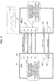
- Table 1 illustrates an example of control logic in which the motor 60 (the vehicle) is controlled based on the ON/OFF states of the accelerator sensor signal and the brake sensor signal by the MCU 40 (the safe mode controller 405).
- Table 1 State Logic Accelerator Sensor ON ON OFF OFF Brake Sensor ON OFF ON OFF Motor Stop Constant speed rotation Stop Stop Vehicle Stop Refuge travelling Stop Stop
- the ON/OFF states of the accelerator sensor signal and the brake sensor signal are determined in comparison with a predetermined threshold. For example, assuming that the threshold of the accelerator sensor signal (voltage) Va is Vth3 and the threshold of the brake sensor signal (voltage) Vb is Vth4, the MCU 40 determines that the accelerator sensor signal is in the "ON" state when Va > Vth3, and determines that the brake sensor signal is in the "ON” state when Vb > Vth4. On the contrary, the MCU 40 determines that the accelerator sensor signal is in the "OFF” state when Va ⁇ Vth3, the brake sensor signal is in the "OFF” state when Vb ⁇ Vth4.
- the comparison between Va and Vth3 and the comparison between Vb and Vth4, for example, can be performed using comparators 411 and 412 (see FIG. 1 ), respectively.
- the comparison results of the comparators 411 and 412 are sent to an arithmetic processing circuit such as a microcomputer serving as the safe mode controller 405, and the control is performed by the arithmetic processing circuit according to the logic listed in Table 1.
- the MCU 40 may be provided with a function of monitoring one or both of the battery voltage (a LiB voltage) of the LiB unit 70 and an IG voltage.
- the MCU 40 may cause the motor 60 to stop (vehicle stop) instead of performing the safe mode control irrespective of the ON/OFF states of the accelerator sensor signal and the brake sensor signal.
- the MCU 40 determines that the LiB unit 70 has not remaining battery capacity sufficient to perform the refuge travelling or that some kinds of errors occur in the LiB unit 70, and performs a stop control on the motor 60 (the vehicle).
- the safe mode controller 405 determines that some kinds of errors occur in the power voltages each supplied to the VCU 30 and the MCU 40, and performs a stop control on the motor 60 (the vehicle).
- the MCU 40 periodically communicates with the VCU 30 through the SPI or the like to thereby periodically monitor whether an error occurs in the VCU 30 (Processes P12 to P14).
- the MCU 40 When a signal is periodically received from the VCU 30, the MCU 40 performs a normal mode control to control the MTM 50 according to the travelling control signal from the VCU 30. As a result, the motor 60 is controlled at a normal rotation speed to cause the vehicle to travel in the normal mode (Process P15).
- the MCU 40 when the signal is not periodically received from the VCU 30, the MCU 40 generates a reset signal using the reset signal generator 402, and transmits the reset signal to the VCU 30 (Process P16).
- the VCU 30 Upon receiving the reset signal from the MCU 40, the VCU 30 shuts down the accelerator sensor power source 301 and the brake sensor power source 302, and stops its operation (Process P17).
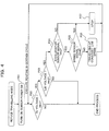
- the MCU 40 After transmitting the reset signal to the VCU 30, the MCU 40 performs the refuge travelling mode (Process P18). For example, as illustrated in FIG. 4 , the MCU 40 performs a control of turning on the sensor power source switch 404 to supply power from the sensor power source 403 to the accelerator sensor 10 and the brake sensor 20 (Process P21).
- the MCU 40 checks the respective voltages by causing the safe mode controller 405 to compare the IG voltage, the LiB voltage, the accelerator sensor signal, and the brake sensor signal with the respective thresholds (Vth1 to Vth4) (Processes P22 to P25).
- the MCU 40 (the safe mode controller 405) ends the process.
- the IG voltage exceeds the threshold Vth1 but the LiB voltage is equal to or less than the threshold Vth2 (YES in Process P22 and NO in Process P23)
- the safe mode controller 405 also ends the process.
- comparisons voltage checking
- thresholds Vth1 and Vth2 are performed in the order of the IG voltage and the LiB voltage as illustrated in FIG. 4
- the comparisons may be performed in the reverse order. Further, the comparisons may be performed at the same timing. Furthermore, the checking of one or both of the IG voltage and the LiB voltage is not essential and may be passed.
- the safe mode controller 405 stops the driving of the motor 60 (vehicle stop) (Process P27).
- the safe mode controller 405 also stops the driving of the motor 60 (vehicle stop) (Process P27).
- the safe mode controller 405 controls the motor 60 at a constant rotational frequency so as to make the vehicle travel at a constant speed (refuge travelling) (Process P26).
- the safe mode controller 405 controls the motor 60 at a constant rotational frequency irrespective of the accelerator stepping amount indicated by the accelerator sensor signal (irrespective of the speed value of the vehicle indicated by the operation signal) so as to make the vehicle travel at a constant speed.
- Processes P22 to P27 may be periodically repeated. Further, in FIG. 4 , although the comparisons (voltage checking) with the thresholds Vth3 and Vth4 are performed in the order of the accelerator sensor signal and the brake sensor signal, the comparisons may be performed in the reverse order. In addition, the comparisons may be performed at the same timing.
- the MCU 40 instead of the VCU 30 controls the motor 60 at a constant rotational frequency based on the ON/OFF logic of the accelerator sensor signal and the brake sensor signal. Therefore, the vehicle can travel for safe refuge.
- FIG. 5 is a block diagram illustrating a modified example of the vehicle control system illustrated in FIG. 1 .
- the vehicle illustrated in FIG. 5 is different in that an inverter error determiner 451 is provided in the MCU 40 (for example, the safe mode controller 405) compared to the configuration depicted in FIG. 1 .
- the inverter error determiner 451 is operable to compare a voltage VDC (for example, a voltage between both ends of an inverter (not illustrated) provided in the MTM 50) between both ends of the MTM 50 and a voltage (the LiB voltage) between both ends of the LiB unit 70.
- VDC can be obtained by the SPI communication as described above.
- the LiB voltage can be obtained from, for example, a battery monitoring module (BTM) which monitors the battery voltage of the LiB unit 70.
- BTM battery monitoring module
- the information of the LiB voltage is input to both of the VCU 30 and the MCU 40.
- the VCU 30 monitors the LiB voltage and performs a control depending on the monitored result (for example, a vehicle speed limitation and the like).
- the MCU 40 checks the LiB voltage and performs a control depending on the check result.
- the MCU 40 determines that an error of the inverter occurs in the MTM 50, and does not perform the above-mentioned safe mode control.
- FIG. 6 illustrates an operational example (a modification of FIG. 4 ).
- Process P31 in which the LiB voltage is compared with the voltage VDC is added by comparison with FIG. 4 .
- the MCU 40 ends the process instead of performing the safe mode control.
- the aforementioned embodiments have been described about an example in which the safe mode control is applied to an automobile (a vehicle) such as the EV and the HEV, but the embodiments may be generally applied to other "ridable machines" such as railway vehicles and ships.
- the ridable machine can be safely evacuated.
Landscapes
- Engineering & Computer Science (AREA)
- Power Engineering (AREA)
- Life Sciences & Earth Sciences (AREA)
- Sustainable Development (AREA)
- Sustainable Energy (AREA)
- Transportation (AREA)
- Mechanical Engineering (AREA)
- Electric Propulsion And Braking For Vehicles (AREA)
- Valves And Accessory Devices For Braking Systems (AREA)
- Control Of Multiple Motors (AREA)
Applications Claiming Priority (1)
| Application Number | Priority Date | Filing Date | Title |
|---|---|---|---|
| JP2013073800A JP2014200126A (ja) | 2013-03-29 | 2013-03-29 | 乗り物用制御システムおよび駆動制御ユニット |
Publications (2)
| Publication Number | Publication Date |
|---|---|
| EP2784609A2 true EP2784609A2 (de) | 2014-10-01 |
| EP2784609A3 EP2784609A3 (de) | 2015-07-08 |
Family
ID=50478685
Family Applications (1)
| Application Number | Title | Priority Date | Filing Date |
|---|---|---|---|
| EP14161074.1A Withdrawn EP2784609A3 (de) | 2013-03-29 | 2014-03-21 | Steuersystem für fahrbare Maschine und Antriebssteuereinheit |
Country Status (4)
| Country | Link |
|---|---|
| US (1) | US20140297078A1 (de) |
| EP (1) | EP2784609A3 (de) |
| JP (1) | JP2014200126A (de) |
| CN (1) | CN104071032A (de) |
Cited By (1)
| Publication number | Priority date | Publication date | Assignee | Title |
|---|---|---|---|---|
| GB2619587A (en) * | 2022-03-30 | 2023-12-13 | Porsche Ag | Modular system |
Families Citing this family (6)
| Publication number | Priority date | Publication date | Assignee | Title |
|---|---|---|---|---|
| JP6427433B2 (ja) * | 2015-02-03 | 2018-11-21 | マイクロスペース株式会社 | モータ駆動装置 |
| JP6561917B2 (ja) * | 2016-06-03 | 2019-08-21 | 株式会社デンソー | 制御装置 |
| WO2020200386A1 (en) * | 2019-04-02 | 2020-10-08 | Universal Robots A/S | Extendable safety system for robot system |
| TWI766604B (zh) * | 2021-03-05 | 2022-06-01 | 台達電子工業股份有限公司 | 用於電動載具中的速度命令產生單元及速度命令產生方法 |
| CN115027280B (zh) * | 2021-03-05 | 2025-06-03 | 台达电子工业股份有限公司 | 用于电动载具中的速度命令产生单元及速度命令产生方法 |
| JP7683556B2 (ja) * | 2022-07-07 | 2025-05-27 | トヨタ自動車株式会社 | 電動車のための制御システム |
Citations (1)
| Publication number | Priority date | Publication date | Assignee | Title |
|---|---|---|---|---|
| JPH04150701A (ja) | 1990-10-12 | 1992-05-25 | Hitachi Ltd | 電気自動車制御装置 |
Family Cites Families (8)
| Publication number | Priority date | Publication date | Assignee | Title |
|---|---|---|---|---|
| JP2844671B2 (ja) * | 1989-05-29 | 1999-01-06 | アイシン精機株式会社 | 内燃機関のスロットル制御方法 |
| DE4192435C1 (de) * | 1990-10-03 | 2002-08-29 | Hitachi Ltd | Steuerung für Elektrofahrzeug |
| US5796179A (en) * | 1995-09-30 | 1998-08-18 | Suzuki Motor Corporation | Vehicle anti-theft device with low voltage compensation and a rolling code |
| EP1616746B1 (de) * | 2004-07-15 | 2010-02-24 | Hitachi, Ltd. | Fahrzeugsteuerungsystem |
| JP4565228B2 (ja) * | 2007-03-08 | 2010-10-20 | 公立大学法人首都大学東京 | 環境対策車 |
| CN201626316U (zh) * | 2009-11-30 | 2010-11-10 | 沈阳工业大学 | 电动汽车无刷双馈电机驱动装置 |
| JP5661752B2 (ja) * | 2010-05-13 | 2015-01-28 | 本田技研工業株式会社 | 車両制御装置 |
| JP5240260B2 (ja) * | 2010-09-13 | 2013-07-17 | 株式会社デンソー | 車両用電子制御装置 |
-
2013
- 2013-03-29 JP JP2013073800A patent/JP2014200126A/ja active Pending
-
2014
- 2014-03-21 EP EP14161074.1A patent/EP2784609A3/de not_active Withdrawn
- 2014-03-26 CN CN201410182526.6A patent/CN104071032A/zh active Pending
- 2014-03-27 US US14/227,668 patent/US20140297078A1/en not_active Abandoned
Patent Citations (1)
| Publication number | Priority date | Publication date | Assignee | Title |
|---|---|---|---|---|
| JPH04150701A (ja) | 1990-10-12 | 1992-05-25 | Hitachi Ltd | 電気自動車制御装置 |
Cited By (2)
| Publication number | Priority date | Publication date | Assignee | Title |
|---|---|---|---|---|
| GB2619587A (en) * | 2022-03-30 | 2023-12-13 | Porsche Ag | Modular system |
| GB2619587B (en) * | 2022-03-30 | 2024-06-05 | Porsche Ag | Modular system |
Also Published As
| Publication number | Publication date |
|---|---|
| CN104071032A (zh) | 2014-10-01 |
| EP2784609A3 (de) | 2015-07-08 |
| JP2014200126A (ja) | 2014-10-23 |
| US20140297078A1 (en) | 2014-10-02 |
Similar Documents
| Publication | Publication Date | Title |
|---|---|---|
| EP2784609A2 (de) | Steuersystem für fahrbare Maschine und Antriebssteuereinheit | |
| US8983695B2 (en) | Electric vehicle and method for controlling same | |
| US10148204B2 (en) | Method for operating an electric machine in a short-circuit mode | |
| CN103863138B (zh) | 补偿燃料电池车电动机速度的装置和方法 | |
| US9106162B2 (en) | Control strategy for an electric machine in a vehicle | |
| US8232756B2 (en) | Motor control apparatus | |
| US9651625B2 (en) | Battery monitoring apparatus and battery monitoring system | |
| US9130487B2 (en) | Control strategy for an electric machine in a vehicle | |
| CN114347808B (zh) | 用于控制交通工具的多模式动力系统的方法和装置 | |
| EP3103669B1 (de) | Steuerungsvorrichtung für ein elektrofahrzeug | |
| US10473446B2 (en) | System and method for determining rotor position offset of an electric machine | |
| KR20140053701A (ko) | E-4wd 하이브리드 전기자동차의 제어장치 및 방법 | |
| US9452680B2 (en) | Vehicle control device | |
| CN101559769A (zh) | 一种电动汽车扭矩安全控制方法 | |
| US20150231972A1 (en) | Control apparatus for vehicle | |
| CN102398589A (zh) | 在具有电动力传动系的车辆中的输出扭矩管控 | |
| US20210036645A1 (en) | Inverter control method, and inverter control apparatus | |
| US20120187899A1 (en) | Power supply system, vehicle provided with same, and control method of power supply system | |
| KR102478078B1 (ko) | 차량용 모터 제어방법 및 시스템 | |
| US10183585B2 (en) | Abnormality informing automotive vehicle | |
| CN111619350A (zh) | 整车控制方法、整车控制系统和一种车辆 | |
| US11420628B2 (en) | Vehicle control method and vehicle control device | |
| JP2015082900A (ja) | 車両制御装置 | |
| US9714029B2 (en) | Vehicle electric machine control strategy | |
| KR102250754B1 (ko) | 하이브리드 전기 자동차의 스마트 크루즈 컨트롤 제어 방법 |
Legal Events
| Date | Code | Title | Description |
|---|---|---|---|
| 17P | Request for examination filed |
Effective date: 20140321 |
|
| AK | Designated contracting states |
Kind code of ref document: A2 Designated state(s): AL AT BE BG CH CY CZ DE DK EE ES FI FR GB GR HR HU IE IS IT LI LT LU LV MC MK MT NL NO PL PT RO RS SE SI SK SM TR |
|
| AX | Request for extension of the european patent |
Extension state: BA ME |
|
| PUAI | Public reference made under article 153(3) epc to a published international application that has entered the european phase |
Free format text: ORIGINAL CODE: 0009012 |
|
| PUAL | Search report despatched |
Free format text: ORIGINAL CODE: 0009013 |
|
| AK | Designated contracting states |
Kind code of ref document: A3 Designated state(s): AL AT BE BG CH CY CZ DE DK EE ES FI FR GB GR HR HU IE IS IT LI LT LU LV MC MK MT NL NO PL PT RO RS SE SI SK SM TR |
|
| AX | Request for extension of the european patent |
Extension state: BA ME |
|
| RIC1 | Information provided on ipc code assigned before grant |
Ipc: G05B 9/02 20060101AFI20150529BHEP Ipc: B60L 11/18 20060101ALI20150529BHEP |
|
| STAA | Information on the status of an ep patent application or granted ep patent |
Free format text: STATUS: THE APPLICATION IS DEEMED TO BE WITHDRAWN |
|
| 18D | Application deemed to be withdrawn |
Effective date: 20160109 |